EP1279006B1 - Sensoranordnung mit zwei resonanzwandlern und einem einzigen leiter - Google Patents
Sensoranordnung mit zwei resonanzwandlern und einem einzigen leiter Download PDFInfo
- Publication number
- EP1279006B1 EP1279006B1 EP01914061A EP01914061A EP1279006B1 EP 1279006 B1 EP1279006 B1 EP 1279006B1 EP 01914061 A EP01914061 A EP 01914061A EP 01914061 A EP01914061 A EP 01914061A EP 1279006 B1 EP1279006 B1 EP 1279006B1
- Authority
- EP
- European Patent Office
- Prior art keywords
- sensor
- sensors
- parameter
- signal
- pressure
- Prior art date
- Legal status (The legal status is an assumption and is not a legal conclusion. Google has not performed a legal analysis and makes no representation as to the accuracy of the status listed.)
- Expired - Lifetime
Links
- 239000004020 conductor Substances 0.000 title claims abstract description 32
- 238000005259 measurement Methods 0.000 claims abstract description 15
- 230000004044 response Effects 0.000 claims description 8
- 230000001419 dependent effect Effects 0.000 claims description 4
- 239000000463 material Substances 0.000 claims description 4
- 230000010355 oscillation Effects 0.000 claims description 4
- 239000003921 oil Substances 0.000 description 9
- 239000012530 fluid Substances 0.000 description 4
- 238000000034 method Methods 0.000 description 3
- 239000003129 oil well Substances 0.000 description 3
- 230000008901 benefit Effects 0.000 description 2
- 230000008859 change Effects 0.000 description 2
- 238000012937 correction Methods 0.000 description 2
- 238000013461 design Methods 0.000 description 2
- 230000000694 effects Effects 0.000 description 2
- 229910052751 metal Inorganic materials 0.000 description 2
- 239000002184 metal Substances 0.000 description 2
- BASFCYQUMIYNBI-UHFFFAOYSA-N platinum Chemical compound [Pt] BASFCYQUMIYNBI-UHFFFAOYSA-N 0.000 description 2
- 239000010453 quartz Substances 0.000 description 2
- VYPSYNLAJGMNEJ-UHFFFAOYSA-N silicon dioxide Inorganic materials O=[Si]=O VYPSYNLAJGMNEJ-UHFFFAOYSA-N 0.000 description 2
- 239000004215 Carbon black (E152) Substances 0.000 description 1
- 229910000831 Steel Inorganic materials 0.000 description 1
- 230000002411 adverse Effects 0.000 description 1
- 230000032683 aging Effects 0.000 description 1
- 238000013459 approach Methods 0.000 description 1
- 239000013078 crystal Substances 0.000 description 1
- 238000010894 electron beam technology Methods 0.000 description 1
- 238000013213 extrapolation Methods 0.000 description 1
- 229930195733 hydrocarbon Natural products 0.000 description 1
- 150000002430 hydrocarbons Chemical class 0.000 description 1
- 238000009434 installation Methods 0.000 description 1
- 230000007774 longterm Effects 0.000 description 1
- 238000004519 manufacturing process Methods 0.000 description 1
- 239000013307 optical fiber Substances 0.000 description 1
- 229910052697 platinum Inorganic materials 0.000 description 1
- 230000036316 preload Effects 0.000 description 1
- 230000005855 radiation Effects 0.000 description 1
- 230000006903 response to temperature Effects 0.000 description 1
- 229910052710 silicon Inorganic materials 0.000 description 1
- 239000010703 silicon Substances 0.000 description 1
- 239000010959 steel Substances 0.000 description 1
- 230000000638 stimulation Effects 0.000 description 1
- NFACJZMKEDPNKN-UHFFFAOYSA-N trichlorfon Chemical compound COP(=O)(OC)C(O)C(Cl)(Cl)Cl NFACJZMKEDPNKN-UHFFFAOYSA-N 0.000 description 1
Images
Classifications
-
- E—FIXED CONSTRUCTIONS
- E21—EARTH OR ROCK DRILLING; MINING
- E21B—EARTH OR ROCK DRILLING; OBTAINING OIL, GAS, WATER, SOLUBLE OR MELTABLE MATERIALS OR A SLURRY OF MINERALS FROM WELLS
- E21B47/00—Survey of boreholes or wells
- E21B47/06—Measuring temperature or pressure
-
- E—FIXED CONSTRUCTIONS
- E21—EARTH OR ROCK DRILLING; MINING
- E21B—EARTH OR ROCK DRILLING; OBTAINING OIL, GAS, WATER, SOLUBLE OR MELTABLE MATERIALS OR A SLURRY OF MINERALS FROM WELLS
- E21B47/00—Survey of boreholes or wells
- E21B47/06—Measuring temperature or pressure
- E21B47/07—Temperature
-
- E—FIXED CONSTRUCTIONS
- E21—EARTH OR ROCK DRILLING; MINING
- E21B—EARTH OR ROCK DRILLING; OBTAINING OIL, GAS, WATER, SOLUBLE OR MELTABLE MATERIALS OR A SLURRY OF MINERALS FROM WELLS
- E21B47/00—Survey of boreholes or wells
- E21B47/12—Means for transmitting measuring-signals or control signals from the well to the surface, or from the surface to the well, e.g. for logging while drilling
-
- G—PHYSICS
- G01—MEASURING; TESTING
- G01L—MEASURING FORCE, STRESS, TORQUE, WORK, MECHANICAL POWER, MECHANICAL EFFICIENCY, OR FLUID PRESSURE
- G01L9/00—Measuring steady of quasi-steady pressure of fluid or fluent solid material by electric or magnetic pressure-sensitive elements; Transmitting or indicating the displacement of mechanical pressure-sensitive elements, used to measure the steady or quasi-steady pressure of a fluid or fluent solid material, by electric or magnetic means
- G01L9/0001—Transmitting or indicating the displacement of elastically deformable gauges by electric, electro-mechanical, magnetic or electro-magnetic means
- G01L9/0008—Transmitting or indicating the displacement of elastically deformable gauges by electric, electro-mechanical, magnetic or electro-magnetic means using vibrations
- G01L9/0022—Transmitting or indicating the displacement of elastically deformable gauges by electric, electro-mechanical, magnetic or electro-magnetic means using vibrations of a piezoelectric element
-
- Y—GENERAL TAGGING OF NEW TECHNOLOGICAL DEVELOPMENTS; GENERAL TAGGING OF CROSS-SECTIONAL TECHNOLOGIES SPANNING OVER SEVERAL SECTIONS OF THE IPC; TECHNICAL SUBJECTS COVERED BY FORMER USPC CROSS-REFERENCE ART COLLECTIONS [XRACs] AND DIGESTS
- Y10—TECHNICAL SUBJECTS COVERED BY FORMER USPC
- Y10S—TECHNICAL SUBJECTS COVERED BY FORMER USPC CROSS-REFERENCE ART COLLECTIONS [XRACs] AND DIGESTS
- Y10S73/00—Measuring and testing
- Y10S73/01—Vibration
Definitions
- the present application relates to sensor apparatus. It seeks to address the long term reliability of such sensors when operated in adverse environments such as elevated temperatures or high radiation levels.
- the application is applicable (inter alia) to the measurement of physical parameters such as pressure, temperature and force, especially in high temperature environments.
- the present invention therefore provides sensor apparatus comprising a plurality of resonant sensors, each of which are connected to a single electrical conductor, each of the sensors having an operating frequency which shifts within a range dependent on at least the parameter sensed by the respective sensor, the ranges of each of the sensors being different.
- a single conductor cable can be used as each is interrogated by a signal along the same conductor.
- the frequency ranges of the sensors are non-overlapping.
- the sensors preferably comprise a vibrating element whose resonant frequency depends on the parameter measured by that sensor. This dependency can be obtained if the sensors further comprise a means for exerting a physical force on the vibrating element dependent on the parameter.
- the physical force can be exerted by holding the vibrating element of that sensor by a member of a material with a different coefficient of thermal expansion.
- the physical force can be exerted by holding the vibrating element of that sensor at one end by a member which is exposed to the relevant pressure and adapted to exert a force in response thereto.
- the vibrating element(s) can be driven by a transducer such as a piezo element.
- the transducer can be driven by an oscillating signal. They will in turn produce an oscillating voltage in response to an oscillation of the vibrating element. It is preferred that the oscillating signal is fed to all transducers via a single conductor.
- the drive signal to the transducer can be applied intermittently. This allows a period during which the system can "listen” for a return signal without it being swamped by the drive signal.
- the system includes a signal analyser to detect signals from the transducers.
- the present invention provides a sensor apparatus for remote parameter measurement in boreholes comprising a measurement head, a cable leading from the measurement head to remote instrumentation, a conductor within the cable leading to transducers within the measurement head which drive and are driven by resonating elements also within the measurement head and whose resonant frequency responds to the measured parameter.
- the present invention thus enables the sensing of multiple parameters over a long single conductor cable.
- two or more resonant sensors can be connected to a common single conductor cable. This overcomes the limitations of the prior art by providing a single conductor sensor that can operate without electronic equipment.
- single conductor sensors required electronic equipment at the sensor in order to provide analysis and multiplexing functions. Such electronics is vulnerable and places a limitation on the equipment life and operating temperature. Sensors without electronic equipment have previously required multiple conductors.
- Each resonant sensor may be set into mechanical vibration by an electrical signal driven from a remote instrumentation package, this signal having a frequency at, or close to, the resonant frequency of the sensor.
- Each resonant sensor is connected to the common cable and is designed to resonate at a range of frequencies that do not overlap with the other sensors connected to the common cable. The precise frequency of resonance for each sensor depends primarily on the value of the physical parameter to be measured by that particular sensor.
- the remote instrumentation package can sweep the electrical drive signal over a range of frequencies and measure the frequency of the response from each of the sensors as each sensor is excited by this electrical drive signal. Each frequency is then converted to a value for the physical parameter being measured by that sensor, using previously recorded calibration information, as is well known.
- the value from one sensor can be used to perform an error correction on other sensors, in a known fashion.
- the value from the temperature sensor is used to apply a correction to (for example) a pressure sensor, as pressure sensors generally have a secondary response to variations in temperature as well as their primary response to variations in pressure.
- a complete frequency sweep is not subsequently required as the instrumentation package may perform a reduced frequency sweep over a narrow range of frequencies close to the last frequency response from each of the sensors.
- the frequency sweep may be halted at the precise resonant frequency of each sensor, to enable accurate measurement of the frequency at that point.
- a sensor with a Q value that is not too high will be excited at its resonant frequency by a drive signal which is merely close.
- frequent stimulation at the last known resonant frequency should be sufficient provided the parameter is not changing too swiftly.
- the drive frequency can be chosen by an algorithm employing historical data to predict a likely value, such as by linear or other extrapolation of a previous trend.
- the electrical drive signal is periodically interrupted, i.e. switched on and off. While the electrical drive signal is switched off, the remote instrumentation package can amplify the signal returned from the sensor, which will still be resonating provided the electrical drive signal was close to the resonant frequency prior to being switched off. This enables the signal from the sensor to be detected over very long cables.
- sensors may be located at different physical locations and connected together by the common single conductor cable.
- sensors may be located at different physical locations and connected together by the common single conductor cable.
- several sensor packages may be located at different depths in the well, connected together by one single conductor cable.
- resonant sensors Many types of electrically driven resonant sensors are known.
- the vibrating wire sensor disclosed in US4255973 is one example.
- Double ended tuning forks (DETFs) are also widely used.
- each tine of the DETF vibrates in anti- phase so that the sensor is balanced. This can provide a relatively high Q factor and reduce the effect of outside influences oh the sensor.
- the resonating element of the sensor is typically made of steel, although quartz and silicon have the well known benefits of low drift and very high "Q" factor.
- resonators are driven either electromagnetically as in the case of US4255973, or using piezoelectric drivers known as PZTs, or the natural piezoelectric effect that occurs in quartz crystals.
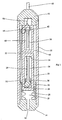
- Figure 1 shows a pressure and temperature gauge for use in oil and gas wells.
- a cylindrical pressure housing 10 is electron beam welded to a cablehead 12 at an upper end and a plug 14 at a lower end.
- upper and lower refer to orientations when the device is in its normal operating state within a well.
- This forms a sealed chamber that can withstand the high pressures required for this form of gauge.
- the fluid in the oil or gas well can enter via a pressure inlet 16 in the plug 14 and into an expansion volume 18 enclosed by bellows 20 sealed to the plug 14 at their lower end and to the base 24 of a closed-ended cylinder 22 at their upper end.
- a pair of tines 26, 28 form a double ended tuning fork that is driven to vibrate in antiphase by a corresponding pair of PZT devices 30, 32.
- the fork thus formed is located within the cylinder 22, the upper end of the fork being attached to the inner face 34 of the upper end of the cylinder 22.
- the lower end of the fork is attached to a mounting 36 that is itself secured to the plug 14.
- the mounting could be secured to the housing 10, but securing the mounting 36 to the plug 14 allows easier assembly and servicing of the device. Slots are formed in the otherwise closed cylinder 22 to allow the mounting 36 to pass through.
- the frequency of vibration of the tines 26, 28 is determined to some extent by temperature but also by the tension force to which they are subject. As the external pressure of the fluid in the oil or gas well increases, the pressure in the expansion volume 18 is applied to the base 24 of the closed-ended cylinder 22 and hence exerted on the upper end of the tines 26, 28 as these are secured to the mounting 36 at their lower end. This increases the natural resonant frequency of the tines 26, 28 with increasing pressure. Thus, the fork defined by tines 26, 28 responds to pressure in the well.
- a second double-ended tuning fork is defined by two further tines, 38, 40. These are also driven to vibrate in antiphase by two further PZT devices 42, 44.
- the second fork is again in a closed cylinder 46 which is secured to the cablehead 12. Again, the cylinder 46 could be secured to the housing 10 but easier access is permitted by the design illustrated.
- the cylinder 46 is made of a material with a higher thermal expansion coefficient than the material from which the tines 42, 44 are constructed. As a result, as the temperature increases the tension in tines 42, 44 also increases, as does their natural resonant frequency. Thus, the second fork responds to the ambient temperature.
- Tuning forks of this type have a natural response to temperature. In some circumstances, therefore, it will be sufficient to rely on this and the cylinder 46 will be unnecessary.
- a cable 48 is secured to the cablehead 12 and consists of an outer metal sheaf sealed to the cablehead 12 to prevent the ingress of fluid.
- a single insulated electrical conductor 50 is contained within the cable 48 and is connected to wiring 52 that leads to all four PZT devices 30, 32, 42, 44.
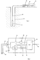
- Figure 2 illustrates an oilwell 54 with cable 48 connected to a pressure and temperature gauge 8 constructed as described in relation to figure 1.
- the cable 48 is connected to instrumentation 56 which is in turn connected to a computer 58 via a serial cable 60.
- FIG. 3 shows the instrumentation 56 in more detail.
- the outer metal sheat 62 of the cable 48 is connected to the instrumentation ground 64. This provides a return path for the electrical drive and the signals passing on electrical conductor 50.
- a digital signal processor (DSP) 66 generates a drive signal that is sent to an amplifier 68 and thence to conductor 50 via a switch 70 Switch 70 is also under the control of the DSP 66 via control line 72.
- DSP digital signal processor
- Any electrical signal returned from the conductor 50 can be amplified in a programmable gain amplifier (PGA) 74 before being digitized by an analogue to digital converter (ADC) 76.
- the PGA 74 is under the control of the DSP 66 and the digital results from the ADC 76 are passed to the DSP 66. Processed results from DSP 66 are passed in digital format to the computer 58 via computer cable 60.
- the DSP 66 controls the sequence of operation. Firstly, switch 70 is closed and a drive signal at a particular frequency is connected to conductor 50. This drive signal travels to the PZT devices 30, 32, 42, 44. If the drive frequency is close to the resonant frequency of a tine, they will be forced into oscillation. It is important to note that the resonant frequency of only one pair of tines, 26, 28 or 38, 40 can be close to any drive frequency, as the tines are designed so that no overlap of resonant frequency occurs, irrespective of the pressure or temperature. This is achieved either by design of the physical aspects of the tines or by placing a preload on one or both pairs of tines. The latter is preferred as the primary purpose of the temperature sensor is to calibrate the pressure sensor, in which case physically identical pairs of tines are preferred.
- switch 70 is opened and the signal from any resonating pair of tines is amplified in PGA 74 before being digitised in ADC 76 and analysed by the DSP 66.
- the DSP 66 controls the gain of PGA 74 via control line 78 to obtain an optimum signal level.
- the DSP 66 obtains the exact frequency of the signal by measuring the time between each zero crossing of the signal, and taking an average. This exact frequency is sent to the computer 58.
- the drive frequency selected for each interrogation sequence sweeps across the possible resonant frequencies of first the pressure sensor and then the temperature sensor, until the resonant frequency of each is found. This can take some time, so thereafter the drive frequency selected when attempting to resonate the pressure sensor is the last measured resonant frequency of the pressure sense, from the previous sequence.
- a similar approach is adopted for the temperature sensor. This enables rapid interrogation of the sensors.
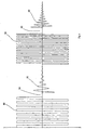
- Figure 4 further illustrates the sequence events in which a time trace of the voltage on the conductor 50 is shown.
- the trace shows the first applied drive frequency at 80, from the amplifier 68 with switch 70 closed.
- the switch 70 is opened, and assuming the drive frequency was close to the resonant frequency of the pressure sensor there will be a return signal 82 from the PZTs 30, 32 resulting from the continued resonance of the tines 26, 28.
- a short gap 84 may be necessary to allow transients from the drive signal to die away.
- the return signal will die away (as shown) as there is now no signal driving the resonating elements.
- the switch 70 is then closed again and the next applied drive frequency 86 for the temperature sensor is applied for a time.
- the switch 70 is opened, and again, if the drive frequency was close to the resonant frequency of the temperature sensor there will be a return signal 88 at the resonant frequncy of the temperature sensor, after a short delay 90.
- This pattern is immediately repeated with the applied drive frequency in each case taken from the actual signal frequency on the previous cycle.
- the drive will then be close to the actual resonant frequency and will excite the sensor to return a signal at that actual frequency.
- the applied drive frequency closely tracks the natural resonant frequency.
- the pressure sensor resonant frequency changes from 4000Hz to 5000Hz over the pressure range 0 psi to 10,000 psi (0-700 bar).
- the temperature sensor resonant frequency changes from 6000Hz to 7000Hz over the temperature range 0 ° C to 200 ° C.
- the resonant frequency ranges do not overlap.
- the DSP 66 When the DSP 66 first powers up, it sweeps the frequency range 4000-5000Hz in 10 Hz steps, looking for the resonance from the pressure sensor. It then sweeps the range 6000-7000Hz in 10Hz steps, looking for the resonance of the temperature sensor. Once these resonances are found, the DSP 66 alternates between the last pressure resonance, and the last temperature resonance as shown in figure 4.
Landscapes
- Physics & Mathematics (AREA)
- Engineering & Computer Science (AREA)
- Geology (AREA)
- Mining & Mineral Resources (AREA)
- Life Sciences & Earth Sciences (AREA)
- Geochemistry & Mineralogy (AREA)
- Fluid Mechanics (AREA)
- Environmental & Geological Engineering (AREA)
- Geophysics (AREA)
- General Life Sciences & Earth Sciences (AREA)
- General Physics & Mathematics (AREA)
- Remote Sensing (AREA)
- Measuring Fluid Pressure (AREA)
- Geophysics And Detection Of Objects (AREA)
- Push-Button Switches (AREA)
- Thermistors And Varistors (AREA)
- Glass Compositions (AREA)
- Measurement Of Length, Angles, Or The Like Using Electric Or Magnetic Means (AREA)
- Measuring Instrument Details And Bridges, And Automatic Balancing Devices (AREA)
- Measurement Of Resistance Or Impedance (AREA)
- Burglar Alarm Systems (AREA)
Claims (14)
- Sensorvorrichtung, die mehrere Resonanzsensoren (26, 28, 38, 40) umfasst, von denen jeder mit einem einzelnen elektrischen Leiter (50) verbunden ist und eine Betriebsfrequenz aufweist, die sich innerhalb eines Bereiches verschiebt, der zumindest von dem durch den jeweiligen Sensor erfassten Parameter abhängig ist, wobei die Bereiche der einzelnen Sensoren (26, 28, 38, 40) unterschiedlich sind.
- Vorrichtung nach Anspruch 1, bei der sich die Frequenzbereiche der Sensoren (26, 28, 38, 40) nicht überlappen.
- Vorrichtung nach Anspruch 1, bei der die Sensoren (26, 28, 38, 40) ein vibrierendes Element (30, 32, 42, 44) umfassen, dessen Resonanzfrequenz von dem durch den jeweiligen Sensor gemessenen Parameter abhängig ist.
- Vorrichtung nach Anspruch 1 oder Anspruch 3, bei der die Sensoren (26, 28, 38, 40) ferner ein Mittel zum Ausüben einer von dem Parameter abhängigen physischen Kraft auf das vibrierende Element (30, 32, 42, 44) umfassen.
- Vorrichtung nach Anspruch 4, bei der der Parameter von mindestens einem Sensor (26, 28, 38, 40) die Temperatur ist und das vibrierende Element (30, 32, 42, 44) dieses Sensors (26, 28, 38, 40) von einem Element aus einem Material gehalten wird, das einen anderen thermischen Ausdehnungskoeffizienten besitzt.
- Vorrichtung nach Anspruch 4 oder Anspruch 5, bei der der Parameter von mindestens einem Sensor (26, 28, 38, 40) der Druck ist und das vibrierende Element dieses Sensors (26, 28, 38, 40) an einem Ende von einem Element gehalten wird, das dem entsprechenden Druck ausgesetzt und so ausgelegt ist, dass es als Reaktion darauf eine Kraft ausübt.
- Vorrichtung nach einem der Ansprüche 1 oder 3 bis 6, bei der das vibrierende Element (30, 32, 42, 44) von einem Umwandler angesteuert wird.
- Vorrichtung nach Anspruch 7, bei der der Umwandler von einem oszillierenden Signal angesteuert wird.
- Vorrichtung nach Anspruch 8, bei der die Umwandler als Reaktion auf ein Schwingen des vibrierenden Elements eine Schwingspannung erzeugen.
- Vorrichtung nach Anspruch 8 oder Anspruch 9, bei der das oszillierende Signal allen Umwandlern über einen einzigen Leiter (50) zugeführt wird.
- Vorrichtung nach einem der Ansprüche 7 bis 10, bei der es sich bei dem Umwandler um ein Piezoelement handelt.
- Vorrichtung nach einem der Ansprüche 7 bis 11, bei der das Ansteuersignal für den Umwandler unstetig ist.
- Vorrichtung nach Anspruch 12, die einen Signalanalysator für das Erfassen von Signalen von den Umwandlern umfasst.
- Sensorvorrichtung nach Anspruch 1 für die Parameter-Fernmessung in Bohrlöchern, die einen Messkopf (8) und ein vom Messkopf (8) zu entfernt liegenden Instrumenten (56) führendes Kabel (48) umfasst, wobei der Leiter (50) in dem Kabel (48) zu Umwandlern in dem Messkopf (8) führt, die jeweils ein Resonanzelement (30, 32, 42, 44) ansteuern bzw. von einem Resonanzelement (30, 32, 42, 44) angesteuert werden, das sich ebenfalls in dem Messkopf (8) befindet und dessen Resonanzfrequenz auf den gemessenen Parameter reagiert.
Applications Claiming Priority (3)
| Application Number | Priority Date | Filing Date | Title |
|---|---|---|---|
| GBGB0007325.4A GB0007325D0 (en) | 2000-03-27 | 2000-03-27 | High temperature sensor |
| GB0007325 | 2000-03-27 | ||
| PCT/GB2001/001326 WO2001073380A1 (en) | 2000-03-27 | 2001-03-27 | Sensor apparatus with two resonant transducers and a single conductor |
Publications (2)
| Publication Number | Publication Date |
|---|---|
| EP1279006A1 EP1279006A1 (de) | 2003-01-29 |
| EP1279006B1 true EP1279006B1 (de) | 2005-12-07 |
Family
ID=9888447
Family Applications (1)
| Application Number | Title | Priority Date | Filing Date |
|---|---|---|---|
| EP01914061A Expired - Lifetime EP1279006B1 (de) | 2000-03-27 | 2001-03-27 | Sensoranordnung mit zwei resonanzwandlern und einem einzigen leiter |
Country Status (8)
| Country | Link |
|---|---|
| US (1) | US7299678B2 (de) |
| EP (1) | EP1279006B1 (de) |
| AT (1) | ATE312336T1 (de) |
| AU (1) | AU3944701A (de) |
| CA (1) | CA2404468C (de) |
| DE (1) | DE60120393D1 (de) |
| GB (2) | GB0007325D0 (de) |
| WO (1) | WO2001073380A1 (de) |
Families Citing this family (31)
| Publication number | Priority date | Publication date | Assignee | Title |
|---|---|---|---|---|
| GB9925373D0 (en) * | 1999-10-27 | 1999-12-29 | Schlumberger Ltd | Downhole instrumentation and cleaning system |
| DE102006039774B4 (de) * | 2006-08-24 | 2011-01-20 | Abb Ag | Messgerät zum Erfassen eines physikalischen/chemischen Messwerts |
| EP2069828A2 (de) | 2006-09-08 | 2009-06-17 | Chevron U.S.A. Inc. | Telemetrievorrichtung und verfahren zur überwachung eines bohrlochs |
| US20090100925A1 (en) * | 2006-10-27 | 2009-04-23 | Baker Hughes Incorporated | System and method for coating flexural mechanical resonators |
| US7444878B1 (en) | 2006-10-30 | 2008-11-04 | Northrop Grumman Systems Corporation | Resonant frequency pressure sensor |
| US9589686B2 (en) | 2006-11-16 | 2017-03-07 | General Electric Company | Apparatus for detecting contaminants in a liquid and a system for use thereof |
| US10914698B2 (en) | 2006-11-16 | 2021-02-09 | General Electric Company | Sensing method and system |
| US9658178B2 (en) | 2012-09-28 | 2017-05-23 | General Electric Company | Sensor systems for measuring an interface level in a multi-phase fluid composition |
| US9538657B2 (en) | 2012-06-29 | 2017-01-03 | General Electric Company | Resonant sensor and an associated sensing method |
| US9536122B2 (en) | 2014-11-04 | 2017-01-03 | General Electric Company | Disposable multivariable sensing devices having radio frequency based sensors |
| US9045973B2 (en) * | 2011-12-20 | 2015-06-02 | General Electric Company | System and method for monitoring down-hole fluids |
| US20080262754A1 (en) * | 2006-11-20 | 2008-10-23 | Alexandre Oudovikine | System and method for fatigue forecasting and strain measurement using Integral Strain Gauge (ISG) |
| US9547104B2 (en) | 2007-09-04 | 2017-01-17 | Chevron U.S.A. Inc. | Downhole sensor interrogation employing coaxial cable |
| US10488286B2 (en) * | 2009-11-30 | 2019-11-26 | Chevron U.S.A. Inc. | System and method for measurement incorporating a crystal oscillator |
| US9470084B2 (en) * | 2010-08-12 | 2016-10-18 | Rosemount Inc. | Method and apparatus for measuring fluid process variable in a well |
| US8542023B2 (en) | 2010-11-09 | 2013-09-24 | General Electric Company | Highly selective chemical and biological sensors |
| WO2013026006A2 (en) | 2011-08-17 | 2013-02-21 | Public Service Solutions, Inc | Passive detectors for imaging systems |
| US9097101B2 (en) * | 2012-03-29 | 2015-08-04 | Chevron U.S.A Inc. | System and method for measurement incorporating a crystal resonator |
| JP6251270B2 (ja) | 2012-08-22 | 2017-12-20 | ゼネラル・エレクトリック・カンパニイ | 機械の動作状態を測定するためのワイヤレスシステムおよび方法 |
| US10598650B2 (en) | 2012-08-22 | 2020-03-24 | General Electric Company | System and method for measuring an operative condition of a machine |
| US10684268B2 (en) | 2012-09-28 | 2020-06-16 | Bl Technologies, Inc. | Sensor systems for measuring an interface level in a multi-phase fluid composition |
| US10195467B2 (en) * | 2013-02-21 | 2019-02-05 | Boston Scientific Scimed, Inc. | Ablation catheter system with wireless radio frequency temperature sensor |
| US9506340B2 (en) * | 2013-03-14 | 2016-11-29 | Sercel-Grc Corporation | Downhole quartz gauge with minimal electronics |
| EP2811269A1 (de) * | 2013-06-06 | 2014-12-10 | VEGA Grieshaber KG | Multigrenzstandmessgerät |
| EP3204605B1 (de) | 2014-12-31 | 2023-06-28 | Halliburton Energy Services, Inc. | System und verfahren zur integrierten mehrfachparametermessung zur leckerkennung |
| WO2016138320A1 (en) * | 2015-02-27 | 2016-09-01 | California Institute Of Technology | Temperature sensor using piezoelectric resonator and methods of measuring temperature |
| US10450855B2 (en) | 2016-04-04 | 2019-10-22 | Sercel-Grc Corp. | System and method for parameter measurement in well |
| EA037631B1 (ru) * | 2020-07-14 | 2021-04-23 | ОБЩЕСТВО С ОГРАНИЧЕННОЙ ОТВЕТСТВЕННОСТЬЮ "Тота Системс" | Способ определения физических величин в скважине на основе пьезорезонансных датчиков без электроники и устройство для его осуществления |
| WO2022036457A1 (en) * | 2020-08-20 | 2022-02-24 | Boss Packaging Inc. | Wireless sensor unit |
| AU2022407663A1 (en) * | 2021-12-07 | 2024-06-20 | Detnet South Africa (Pty) Ltd | Borehole temperature monitoring |
| US12460540B2 (en) * | 2022-09-27 | 2025-11-04 | Baker Hughes Oilfield Operations Llc | Pressure sensor and borehole system |
Family Cites Families (19)
| Publication number | Priority date | Publication date | Assignee | Title |
|---|---|---|---|---|
| US3355949A (en) * | 1964-08-17 | 1967-12-05 | Albert A Elwood | Crystal temperature and pressure transucer |
| US4102195A (en) * | 1977-02-08 | 1978-07-25 | Westinghouse Electric Corp. | Hot spot temperature sensor |
| US4459042A (en) * | 1980-11-28 | 1984-07-10 | Novex, Inc. | Vibratory digital temperature sensor |
| US4535638A (en) | 1983-10-03 | 1985-08-20 | Quartztronics, Inc. | Resonator transducer system with temperature compensation |
| US4607530A (en) | 1984-11-01 | 1986-08-26 | Schlumberger Technology Corporation | Temperature compensation for pressure gauges |
| GB8610252D0 (en) * | 1986-04-26 | 1986-06-25 | Stc Plc | Remote sensor |
| US4760351A (en) * | 1986-08-22 | 1988-07-26 | Northern Illinois University | Multiple oscillator device having plural quartz resonators in a common quartz substrate |
| US4878226A (en) * | 1987-02-09 | 1989-10-31 | Combustion Engineering, Inc. | Multiple point remote temperature sensing |
| GB8705151D0 (en) * | 1987-03-05 | 1987-04-08 | Univ Strathclyde | Optically excited vibratile transducer |
| US4972076A (en) * | 1988-09-29 | 1990-11-20 | Schlumberger Industries Limited | Solid state sensor with dual resonant vibratable members |
| US5379639A (en) * | 1992-12-10 | 1995-01-10 | Alliedsignal Inc. | Combined force transducer and temperature sensor |
| US5299868A (en) * | 1993-02-03 | 1994-04-05 | Halliburton Company | Crystalline transducer with ac-cut temperature crystal |
| US5445008A (en) * | 1994-03-24 | 1995-08-29 | Martin Marietta Energy Systems, Inc. | Microbar sensor |
| US5488866A (en) * | 1994-04-11 | 1996-02-06 | Tektronix, Inc. | Time-interleaved method for efficient operation of an acoustic wave sensor array |
| US5836691A (en) | 1996-07-17 | 1998-11-17 | Techno Togo Limited Company | Method of thermometry and apparatus for the thermometry |
| US6494079B1 (en) * | 2001-03-07 | 2002-12-17 | Symyx Technologies, Inc. | Method and apparatus for characterizing materials by using a mechanical resonator |
| US6359444B1 (en) * | 1999-05-28 | 2002-03-19 | University Of Kentucky Research Foundation | Remote resonant-circuit analyte sensing apparatus with sensing structure and associated method of sensing |
| GB2352814B (en) * | 1999-07-28 | 2003-04-09 | Transense Technologies Plc | Pressure monitor system |
| GB2355801B (en) * | 1999-10-29 | 2003-07-30 | Transense Technologies Plc | Interrogation of surface acoustical wave devices |
-
2000
- 2000-03-27 GB GBGB0007325.4A patent/GB0007325D0/en not_active Ceased
-
2001
- 2001-03-27 GB GB0107594A patent/GB2365972B/en not_active Revoked
- 2001-03-27 EP EP01914061A patent/EP1279006B1/de not_active Expired - Lifetime
- 2001-03-27 AU AU39447/01A patent/AU3944701A/en not_active Abandoned
- 2001-03-27 DE DE60120393T patent/DE60120393D1/de not_active Expired - Fee Related
- 2001-03-27 CA CA2404468A patent/CA2404468C/en not_active Expired - Fee Related
- 2001-03-27 WO PCT/GB2001/001326 patent/WO2001073380A1/en not_active Ceased
- 2001-03-27 US US10/240,134 patent/US7299678B2/en not_active Expired - Fee Related
- 2001-03-27 AT AT01914061T patent/ATE312336T1/de not_active IP Right Cessation
Also Published As
| Publication number | Publication date |
|---|---|
| GB0107594D0 (en) | 2001-05-16 |
| DE60120393D1 (de) | 2006-07-20 |
| WO2001073380A1 (en) | 2001-10-04 |
| CA2404468C (en) | 2011-06-14 |
| US7299678B2 (en) | 2007-11-27 |
| ATE312336T1 (de) | 2005-12-15 |
| EP1279006A1 (de) | 2003-01-29 |
| AU3944701A (en) | 2001-10-08 |
| CA2404468A1 (en) | 2001-10-04 |
| GB2365972B (en) | 2004-07-14 |
| GB2365972A (en) | 2002-02-27 |
| GB0007325D0 (en) | 2000-05-17 |
| US20030101822A1 (en) | 2003-06-05 |
Similar Documents
| Publication | Publication Date | Title |
|---|---|---|
| EP1279006B1 (de) | Sensoranordnung mit zwei resonanzwandlern und einem einzigen leiter | |
| US6598481B1 (en) | Quartz pressure transducer containing microelectronics | |
| CA2599629C (en) | A density and viscosity sensor | |
| EP1804048B1 (de) | Dichte- und Viskositätssensor | |
| RU2511629C2 (ru) | Способ и устройство для измерения давления с использованием наполнительной трубы | |
| US6131462A (en) | Pressure/temperature transducer with improved thermal coupling and enhanced transient response | |
| US4620446A (en) | Acceleration responsive transducers | |
| US7784350B2 (en) | Downhole transducer with adjacent heater | |
| US7862228B2 (en) | High temperature wellbore monitoring method and apparatus | |
| US9651440B2 (en) | Passive pressure sensing using sensor with diaphragm separator | |
| US9625339B2 (en) | Passive pressure sensing using sensor with disk resonator | |
| US9625338B2 (en) | Passive pressure sensing using sensor with resonator having bridged ends | |
| US20150377728A1 (en) | Passive pressure sensing | |
| US20040079160A1 (en) | Pressure transducer | |
| RU2804066C1 (ru) | Устройство для измерения вязкости бурового раствора на забое скважины в процессе бурения | |
| KR102815125B1 (ko) | 유체의 점도 측정 장치 | |
| MXPA01010230A (es) | Un metodo de medicion de presion por medio de un manometro que tiene un elemento resonante. | |
| Hoeppner | Industrial radio telemetry | |
| WO2015084514A1 (en) | Passive pressure sensing |
Legal Events
| Date | Code | Title | Description |
|---|---|---|---|
| PUAI | Public reference made under article 153(3) epc to a published international application that has entered the european phase |
Free format text: ORIGINAL CODE: 0009012 |
|
| 17P | Request for examination filed |
Effective date: 20020927 |
|
| AK | Designated contracting states |
Designated state(s): AT BE CH CY DE DK ES FI FR GB GR IE IT LI LU MC NL PT SE TR |
|
| AX | Request for extension of the european patent |
Extension state: AL LT LV MK RO SI |
|
| RAP1 | Party data changed (applicant data changed or rights of an application transferred) |
Owner name: PLUS DESIGN LIMITED |
|
| RIN1 | Information on inventor provided before grant (corrected) |
Inventor name: ATHERTON, ERIC JOHN |
|
| 17Q | First examination report despatched |
Effective date: 20040910 |
|
| GRAP | Despatch of communication of intention to grant a patent |
Free format text: ORIGINAL CODE: EPIDOSNIGR1 |
|
| GRAS | Grant fee paid |
Free format text: ORIGINAL CODE: EPIDOSNIGR3 |
|
| GRAA | (expected) grant |
Free format text: ORIGINAL CODE: 0009210 |
|
| AK | Designated contracting states |
Kind code of ref document: B1 Designated state(s): AT BE CH CY DE DK ES FI FR GB GR IE IT LI LU MC NL PT SE TR |
|
| PG25 | Lapsed in a contracting state [announced via postgrant information from national office to epo] |
Ref country code: FI Free format text: LAPSE BECAUSE OF FAILURE TO SUBMIT A TRANSLATION OF THE DESCRIPTION OR TO PAY THE FEE WITHIN THE PRESCRIBED TIME-LIMIT Effective date: 20051207 Ref country code: IT Free format text: LAPSE BECAUSE OF FAILURE TO SUBMIT A TRANSLATION OF THE DESCRIPTION OR TO PAY THE FEE WITHIN THE PRESCRIBED TIME-LIMIT;WARNING: LAPSES OF ITALIAN PATENTS WITH EFFECTIVE DATE BEFORE 2007 MAY HAVE OCCURRED AT ANY TIME BEFORE 2007. THE CORRECT EFFECTIVE DATE MAY BE DIFFERENT FROM THE ONE RECORDED. Effective date: 20051207 Ref country code: AT Free format text: LAPSE BECAUSE OF FAILURE TO SUBMIT A TRANSLATION OF THE DESCRIPTION OR TO PAY THE FEE WITHIN THE PRESCRIBED TIME-LIMIT Effective date: 20051207 Ref country code: CH Free format text: LAPSE BECAUSE OF FAILURE TO SUBMIT A TRANSLATION OF THE DESCRIPTION OR TO PAY THE FEE WITHIN THE PRESCRIBED TIME-LIMIT Effective date: 20051207 Ref country code: LI Free format text: LAPSE BECAUSE OF FAILURE TO SUBMIT A TRANSLATION OF THE DESCRIPTION OR TO PAY THE FEE WITHIN THE PRESCRIBED TIME-LIMIT Effective date: 20051207 Ref country code: BE Free format text: LAPSE BECAUSE OF FAILURE TO SUBMIT A TRANSLATION OF THE DESCRIPTION OR TO PAY THE FEE WITHIN THE PRESCRIBED TIME-LIMIT Effective date: 20051207 Ref country code: NL Free format text: LAPSE BECAUSE OF FAILURE TO SUBMIT A TRANSLATION OF THE DESCRIPTION OR TO PAY THE FEE WITHIN THE PRESCRIBED TIME-LIMIT Effective date: 20051207 |
|
| REG | Reference to a national code |
Ref country code: GB Ref legal event code: FG4D |
|
| RIN1 | Information on inventor provided before grant (corrected) |
Inventor name: ATHERTON, ERIC JOHN |
|
| REG | Reference to a national code |
Ref country code: CH Ref legal event code: EP |
|
| REG | Reference to a national code |
Ref country code: IE Ref legal event code: FG4D |
|
| PG25 | Lapsed in a contracting state [announced via postgrant information from national office to epo] |
Ref country code: GR Free format text: LAPSE BECAUSE OF FAILURE TO SUBMIT A TRANSLATION OF THE DESCRIPTION OR TO PAY THE FEE WITHIN THE PRESCRIBED TIME-LIMIT Effective date: 20060307 Ref country code: SE Free format text: LAPSE BECAUSE OF FAILURE TO SUBMIT A TRANSLATION OF THE DESCRIPTION OR TO PAY THE FEE WITHIN THE PRESCRIBED TIME-LIMIT Effective date: 20060307 Ref country code: DK Free format text: LAPSE BECAUSE OF FAILURE TO SUBMIT A TRANSLATION OF THE DESCRIPTION OR TO PAY THE FEE WITHIN THE PRESCRIBED TIME-LIMIT Effective date: 20060307 |
|
| PG25 | Lapsed in a contracting state [announced via postgrant information from national office to epo] |
Ref country code: ES Free format text: LAPSE BECAUSE OF FAILURE TO SUBMIT A TRANSLATION OF THE DESCRIPTION OR TO PAY THE FEE WITHIN THE PRESCRIBED TIME-LIMIT Effective date: 20060318 |
|
| PG25 | Lapsed in a contracting state [announced via postgrant information from national office to epo] |
Ref country code: IE Free format text: LAPSE BECAUSE OF NON-PAYMENT OF DUE FEES Effective date: 20060327 |
|
| PG25 | Lapsed in a contracting state [announced via postgrant information from national office to epo] |
Ref country code: LU Free format text: LAPSE BECAUSE OF NON-PAYMENT OF DUE FEES Effective date: 20060331 Ref country code: MC Free format text: LAPSE BECAUSE OF NON-PAYMENT OF DUE FEES Effective date: 20060331 |
|
| PG25 | Lapsed in a contracting state [announced via postgrant information from national office to epo] |
Ref country code: PT Free format text: LAPSE BECAUSE OF FAILURE TO SUBMIT A TRANSLATION OF THE DESCRIPTION OR TO PAY THE FEE WITHIN THE PRESCRIBED TIME-LIMIT Effective date: 20060508 |
|
| NLV1 | Nl: lapsed or annulled due to failure to fulfill the requirements of art. 29p and 29m of the patents act | ||
| REG | Reference to a national code |
Ref country code: CH Ref legal event code: PL |
|
| REF | Corresponds to: |
Ref document number: 60120393 Country of ref document: DE Date of ref document: 20060720 Kind code of ref document: P |
|
| ET | Fr: translation filed | ||
| PG25 | Lapsed in a contracting state [announced via postgrant information from national office to epo] |
Ref country code: DE Free format text: LAPSE BECAUSE OF NON-PAYMENT OF DUE FEES Effective date: 20061003 |
|
| REG | Reference to a national code |
Ref country code: GB Ref legal event code: 732E |
|
| PLBE | No opposition filed within time limit |
Free format text: ORIGINAL CODE: 0009261 |
|
| STAA | Information on the status of an ep patent application or granted ep patent |
Free format text: STATUS: NO OPPOSITION FILED WITHIN TIME LIMIT |
|
| 26N | No opposition filed |
Effective date: 20060908 |
|
| REG | Reference to a national code |
Ref country code: IE Ref legal event code: MM4A |
|
| REG | Reference to a national code |
Ref country code: GB Ref legal event code: 732E |
|
| PG25 | Lapsed in a contracting state [announced via postgrant information from national office to epo] |
Ref country code: TR Free format text: LAPSE BECAUSE OF FAILURE TO SUBMIT A TRANSLATION OF THE DESCRIPTION OR TO PAY THE FEE WITHIN THE PRESCRIBED TIME-LIMIT Effective date: 20051207 |
|
| PG25 | Lapsed in a contracting state [announced via postgrant information from national office to epo] |
Ref country code: CY Free format text: LAPSE BECAUSE OF FAILURE TO SUBMIT A TRANSLATION OF THE DESCRIPTION OR TO PAY THE FEE WITHIN THE PRESCRIBED TIME-LIMIT Effective date: 20051207 |
|
| REG | Reference to a national code |
Ref country code: FR Ref legal event code: PLFP Year of fee payment: 16 |
|
| REG | Reference to a national code |
Ref country code: FR Ref legal event code: PLFP Year of fee payment: 17 |
|
| REG | Reference to a national code |
Ref country code: FR Ref legal event code: PLFP Year of fee payment: 18 |
|
| PGFP | Annual fee paid to national office [announced via postgrant information from national office to epo] |
Ref country code: GB Payment date: 20180321 Year of fee payment: 18 |
|
| PGFP | Annual fee paid to national office [announced via postgrant information from national office to epo] |
Ref country code: FR Payment date: 20180223 Year of fee payment: 18 |
|
| GBPC | Gb: european patent ceased through non-payment of renewal fee |
Effective date: 20190327 |
|
| PG25 | Lapsed in a contracting state [announced via postgrant information from national office to epo] |
Ref country code: GB Free format text: LAPSE BECAUSE OF NON-PAYMENT OF DUE FEES Effective date: 20190327 |
|
| PG25 | Lapsed in a contracting state [announced via postgrant information from national office to epo] |
Ref country code: FR Free format text: LAPSE BECAUSE OF NON-PAYMENT OF DUE FEES Effective date: 20190331 |