EP1279008B1 - Detecteur de debit pour fluides - Google Patents
Detecteur de debit pour fluides Download PDFInfo
- Publication number
- EP1279008B1 EP1279008B1 EP01921723A EP01921723A EP1279008B1 EP 1279008 B1 EP1279008 B1 EP 1279008B1 EP 01921723 A EP01921723 A EP 01921723A EP 01921723 A EP01921723 A EP 01921723A EP 1279008 B1 EP1279008 B1 EP 1279008B1
- Authority
- EP
- European Patent Office
- Prior art keywords
- semiconductor device
- flow sensor
- tube section
- tube
- sensor according
- Prior art date
- Legal status (The legal status is an assumption and is not a legal conclusion. Google has not performed a legal analysis and makes no representation as to the accuracy of the status listed.)
- Expired - Lifetime
Links
- 239000004065 semiconductor Substances 0.000 claims abstract description 59
- 239000007788 liquid Substances 0.000 claims abstract description 12
- 238000005259 measurement Methods 0.000 claims abstract description 3
- 238000004519 manufacturing process Methods 0.000 claims description 8
- 239000002184 metal Substances 0.000 claims description 8
- 229910052751 metal Inorganic materials 0.000 claims description 8
- 239000012528 membrane Substances 0.000 claims description 7
- 239000004033 plastic Substances 0.000 claims description 6
- 239000000463 material Substances 0.000 claims description 5
- 239000011888 foil Substances 0.000 claims description 4
- 239000012790 adhesive layer Substances 0.000 claims description 3
- 238000000034 method Methods 0.000 claims description 3
- 229910000679 solder Inorganic materials 0.000 claims description 3
- 238000012545 processing Methods 0.000 claims description 2
- 230000035945 sensitivity Effects 0.000 abstract description 5
- 239000010410 layer Substances 0.000 description 4
- 239000000758 substrate Substances 0.000 description 4
- 239000000853 adhesive Substances 0.000 description 3
- 230000001070 adhesive effect Effects 0.000 description 3
- 238000009826 distribution Methods 0.000 description 3
- 238000002161 passivation Methods 0.000 description 3
- 239000004696 Poly ether ether ketone Substances 0.000 description 2
- 239000011521 glass Substances 0.000 description 2
- 239000004519 grease Substances 0.000 description 2
- 229920002530 polyetherether ketone Polymers 0.000 description 2
- OKTJSMMVPCPJKN-UHFFFAOYSA-N Carbon Chemical compound [C] OKTJSMMVPCPJKN-UHFFFAOYSA-N 0.000 description 1
- RYGMFSIKBFXOCR-UHFFFAOYSA-N Copper Chemical compound [Cu] RYGMFSIKBFXOCR-UHFFFAOYSA-N 0.000 description 1
- 239000004642 Polyimide Substances 0.000 description 1
- 229910052581 Si3N4 Inorganic materials 0.000 description 1
- VYPSYNLAJGMNEJ-UHFFFAOYSA-N Silicium dioxide Chemical compound O=[Si]=O VYPSYNLAJGMNEJ-UHFFFAOYSA-N 0.000 description 1
- 239000004809 Teflon Substances 0.000 description 1
- 229920006362 Teflon® Polymers 0.000 description 1
- 238000004026 adhesive bonding Methods 0.000 description 1
- 229910052799 carbon Inorganic materials 0.000 description 1
- 239000011248 coating agent Substances 0.000 description 1
- 238000000576 coating method Methods 0.000 description 1
- 229910052802 copper Inorganic materials 0.000 description 1
- 239000010949 copper Substances 0.000 description 1
- 230000001419 dependent effect Effects 0.000 description 1
- 229910003460 diamond Inorganic materials 0.000 description 1
- 239000010432 diamond Substances 0.000 description 1
- 238000009792 diffusion process Methods 0.000 description 1
- 238000011156 evaluation Methods 0.000 description 1
- 239000003292 glue Substances 0.000 description 1
- PCHJSUWPFVWCPO-UHFFFAOYSA-N gold Chemical compound [Au] PCHJSUWPFVWCPO-UHFFFAOYSA-N 0.000 description 1
- 229910052737 gold Inorganic materials 0.000 description 1
- 239000010931 gold Substances 0.000 description 1
- 238000010438 heat treatment Methods 0.000 description 1
- 238000009413 insulation Methods 0.000 description 1
- 229920001721 polyimide Polymers 0.000 description 1
- 239000011241 protective layer Substances 0.000 description 1
- 238000007789 sealing Methods 0.000 description 1
- HQVNEWCFYHHQES-UHFFFAOYSA-N silicon nitride Chemical compound N12[Si]34N5[Si]62N3[Si]51N64 HQVNEWCFYHHQES-UHFFFAOYSA-N 0.000 description 1
- 229910052814 silicon oxide Inorganic materials 0.000 description 1
- 239000000126 substance Substances 0.000 description 1
- 150000003457 sulfones Chemical class 0.000 description 1
- 238000012546 transfer Methods 0.000 description 1
- 238000003466 welding Methods 0.000 description 1
Images


Classifications
-
- G—PHYSICS
- G01—MEASURING; TESTING
- G01F—MEASURING VOLUME, VOLUME FLOW, MASS FLOW OR LIQUID LEVEL; METERING BY VOLUME
- G01F1/00—Measuring the volume flow or mass flow of fluid or fluent solid material wherein the fluid passes through a meter in a continuous flow
- G01F1/68—Measuring the volume flow or mass flow of fluid or fluent solid material wherein the fluid passes through a meter in a continuous flow by using thermal effects
- G01F1/684—Structural arrangements; Mounting of elements, e.g. in relation to fluid flow
- G01F1/6847—Structural arrangements; Mounting of elements, e.g. in relation to fluid flow where sensing or heating elements are not disturbing the fluid flow, e.g. elements mounted outside the flow duct
-
- G—PHYSICS
- G01—MEASURING; TESTING
- G01F—MEASURING VOLUME, VOLUME FLOW, MASS FLOW OR LIQUID LEVEL; METERING BY VOLUME
- G01F1/00—Measuring the volume flow or mass flow of fluid or fluent solid material wherein the fluid passes through a meter in a continuous flow
- G01F1/68—Measuring the volume flow or mass flow of fluid or fluent solid material wherein the fluid passes through a meter in a continuous flow by using thermal effects
- G01F1/684—Structural arrangements; Mounting of elements, e.g. in relation to fluid flow
- G01F1/6845—Micromachined devices
Definitions
- the invention relates to a flow sensor for a liquid according to the preamble of claim 1 and a method for its production.
- semiconductor devices of this type are sensitive. In contact with liquids, it is easy to unwanted diffusion of substances affecting the properties of the block. In addition, mechanical Stress damage the component. Therefore for example, the semiconductor devices must be complexly processed, e.g. protected by protective layers.
- the semiconductor device So arranged on the outside of a pipe section, and Although in such a way that he with this outside in thermal Contact stands. Surprisingly, it turns out that such an arrangement is still accurate and sensitive Measurements allowed. As the liquid in the pipe section is guided and not with the semiconductor device or with whose passivation layers comes into contact, damage can be avoided.
- the semiconductor device may e.g. in direct thermal contact with the tube outside, or he can with this over sauceleitense, e.g. made of metal, be connected.
- an adhesive layer be, e.g. from a solder, or it may be thermal grease be used.
- the pipe piece may e.g. made of glass or metal being, being metal because of its high thermal conductivity is preferred.
- the pipe section may be in one piece or out consist of several individual pieces of pipe.
- the outside of the tube in the area of the semiconductor device flattened be designed and / or the tube has a thinned wall area.
- the basic structure of the flow sensor results from the first embodiment shown in Fig. 1-3. It consists of a semiconductor chip 1, the is arranged on the outside of a pipe section 2, through which the liquid to be measured flows. For fixation of the semiconductor device 1 on the pipe section 2 is in this version provided a cured adhesive 3.
- thermopile As can be seen in particular from FIG. 3, there is the semiconductor device 1 from a substrate 1a, on which a heat source 5 in the form of an integrated resistor is arranged.
- a heat source 5 in the form of an integrated resistor is arranged.
- two temperature sensors 6a, 6b In the present preferred The temperature sensors are designed as thermopile designed.
- an opening 7 is etched, which is covered by a thin dielectric membrane 8 is.
- the heat source 5 and the heat source side Contact rows of the thermopile 6a, 6b are on the membrane 8 arranged. By this arrangement, the heat conduction between the heat source 5 and the temperature sensors reduced.
- the heat source 5 and the thermopile 6a, 6b are on their top with a dielectric passivation layer (not shown) e.g. made of silicon oxide or silicon nitride.
- thermopile 6a, 6b or their passivation layer are in thermal contact with the outside of the pipe 2. You can see the outside of the Touch the pipe directly or from this through a thin one Layer of adhesive material, thermal grease or solder be separated.
- an evaluation 10 On the substrate 4 is also an evaluation 10 arranged. This includes e.g. a preamp, an analog-to-digital converter and a digital one Processing stage, e.g. to the signal of the thermopile to linearize and scale, as well as the control for the heat source. For electrical connection with the outside world connecting pads 11 are provided.
- the transmitter 10 is configured, around the heat source 5 with constant current, more constant Temperature or constant voltage. Further measures the difference ⁇ of the temperature differences above the thermopile 6a, 6b. As the outer contact rows the thermopile 6a, 6b substantially the same Temperature, the difference ⁇ substantially the temperature difference at the inner contact rows.
- the heat source 5 In operation, the heat source 5 generates a Temperature distribution in the wall of the pipe 2. By the Flow of liquid in the pipe 2 becomes this temperature distribution asymmetric, so the difference ⁇ of the temperature differences a measure of the river's speed is.
- the pipe section 2 is independent of the semiconductor device 1 made and self-supporting. It exists preferably made of metal and has a wall thickness of preferably less than 0.5 mm, giving good sensitivity is reached. It turns out, however, that thanks the high sensitivity of the semiconductor device also pieces of pipe can be used with thicker walls.
- tubes made of glass or plastic can also be used.
- FIG. 4 A second embodiment of the invention is disclosed in Fig. 4 shown.
- the semiconductor device 1 not directly on the outside of the pipe section 2. Rather, between the semiconductor device 1 and the Pipe 2 three heat conducting elements 12 are arranged. It can it is e.g. "Metal bumps", i. E. around surveys of metal, preferably of gold or copper, each over the inner contact rows of the thermopile 6a, 6b and the heater 5 are and with these ever a thermal Make contact.
- the arrangement according to FIG. 4 has the Advantage that the semiconductor device 1 with the pipe section 2 only at well-defined locations in thermal contact stands.
- the semiconductor device according to FIG. 4 may be like that according to FIG. 1 also covered with an adhesive become.
- Figs. 5 and 6 show another embodiment the invention, wherein the semiconductor device 1 of a Housing 13 is protected.
- the housing 13 is preferably made of plastic and has e.g. a suitable one Recess for receiving the semiconductor device 1.
- the Semiconductor device 1 is over bonding wires 18 with a printed Circuit 15 connected.
- the printed circuit 15 is used for mounting of connecting wires 16 and is with mechanically connected to the housing 13, so that on the connecting wires 16 attacking forces not directly on the Semiconductor module 1 can be transmitted.
- Glue 3 For covering the semiconductor device 1 and for attaching the housing 13 to the tube 2 is in turn a Glue 3 provided.
- the pipe section 2 has the pipe section 2 a cylindrical outer surface.
- the outer surface of the pipe section 2 in the region of the semiconductor device 1 preferably however flattened designed.
- the pipe section is the second cylindrical, but was flattened in a region 17.
- the pipe section 2 is substantially rectangular and has a recess 19, in which the semiconductor device 1 is arranged.
- the pipe section 2 has a smaller wall thickness on than on the other walls.
- the tube 2 is shown in one piece, i. of the Cross section of the tube in the area of the sensor is from a Part formed.
- the tube 2 can also Herstükkig be constructed so that the pipe cross-section forming Pipe walls are formed of several parts.
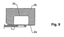
- FIG. 9 A corresponding embodiment is in Fig. 9 shown.
- the tube 2 from a first Tube part 2a and a second pipe part 2b formed.
- pipe part 2b consists of a block of material in which a Groove or groove 20 is arranged.
- Pipe part 2a has the shape of a thin plate or foil and extends over the groove 20.
- the semiconductor device 1 is in thermal contact with tube part 2a and is on whose outside is arranged.
- pipe part 2a forms a wall of the tube 2 and separates the interior of the Semiconductor device 1.
- FIG. 9 has various Advantages.
- tube part 2 a separately from Tube part 2b are made. This allows pipe part 2a as a plate or foil with a very well-defined thickness to manufacture. Since pipe part 2a is manufactured separately, must he would be self-supporting.
- Tube part 2a can sealing after its production be connected to tube part 2b, e.g. by gluing or welding.
- the manufactured independently of tube part 2a Semiconductor device 1 is before or after connecting the Pipe parts 2a and 2b attached to the pipe part 2a.
- tube part 2a consists of a Plastic, e.g. PEEK (polyetheretherketone), Teflon Polyaryl sulfone (PSU) or polyimide. His thickness is given through the desired strength and thermal conductivity. But to be self-supporting, he should have one Thickness of at least 10 ⁇ m, preferably at least 25 ⁇ m.
- PEEK polyetheretherketone
- PSU Teflon Polyaryl sulfone
- polyimide polyimide
- Fig. 9 Another advantage of the embodiment according to Fig. 9 is that the tube interior in the production is accessible and thus in a simple way completely or partially coated, e.g. with a hardening, anti-sticking and / or passivating coating, For example, DLC (Diamond Like Carbon). Either Blank 2a, as well as tube 2b can be coated be.
- a hardening, anti-sticking and / or passivating coating For example, DLC (Diamond Like Carbon).
- Either Blank 2a, as well as tube 2b can be coated be.
- An additional advantage of a separate production a plurality of pipe parts 2a, 2b is that the Pipe part 2a, the semiconductor device 1 from the interior of the Pipe separates, in view of a desired measuring range or a desired measuring medium selected specifically can be.
- Pipe part 2a made of plastic and pipe part 2b Metal can be.
- Semiconductor device 1 is an opening 7 and a membrane 8 provided, on which both the heater 5 and the inner contacts of the thermopile 6a, 6b are located.
- a alternative embodiment is shown in Fig. 10.
- three openings are provided in the semiconductor device 1, of which the middle under the heater 5 and the outside under the outer contact rows of the thermopile 6a, 6b, and the respective membranes 8a, 8b and 8c are covered. Also with this architecture arises a good thermal insulation between the temperature sensors and the heater.
Landscapes
- Physics & Mathematics (AREA)
- Fluid Mechanics (AREA)
- General Physics & Mathematics (AREA)
- Measuring Volume Flow (AREA)
- Sampling And Sample Adjustment (AREA)
- Investigating Or Analyzing Materials By The Use Of Electric Means (AREA)
- Geophysics And Detection Of Objects (AREA)
Claims (21)
- Détecteur de débit pour un fluide avec un module à semi-conducteurs (1), sur lequel est intégré au moins un capteur de température (6a,6b) et une source de chaleur (5), caractérisé par un élément tubulaire (2) pour le guidage du liquide, dans lequel le module à semi-conducteurs (1) est disposé sur le côté extérieur de l'élément tubulaire (2), et dans lequel le capteur de température (6a,6b) et la source de chaleur (5) sont en contact thermique avec le côté extérieur de l'élément tubulaire (2).
- Détecteur de débit selon la revendication 1, dans lequel le au moins un capteur de température (6a, 6b) et la source de chaleur (5) sont en contact direct avec le côté extérieur de l'élément tubulaire (2).
- Détecteur de débit selon la revendication 1, dans lequel le au moins un capteur de température (6a, 6b) et la source de chaleur sont en contact par le biais d'éléments conducteurs de chaleur (12), en particulier par le biais d'éléments conducteurs de chaleur métalliques, avec le côté extérieur de l'élément tubulaire (2).
- Détecteur de débit selon l'une des revendications 1 ou 3, dans lequel une couche adhésive est disposée entre le module à semi-conducteurs (1) et l'élément tubulaire (2).
- Détecteur de débit selon la revendication 4, dans lequel la couche adhésive est un métal d'apport de brasage durci.
- Détecteur de débit selon l'une des revendications 1 ou 3, dans lequel entre le module à semi-conducteurs (1) et l'élément tubulaire (2) est disposée une pâte conductrice de chaleur.
- Détecteur de débit selon l'une des revendications précédentes, dans lequel le module à semi-conducteurs (1) est collé sur l'élément tubulaire (2).
- Détecteur de débit selon l'une des revendications précédentes, caractérisé en ce que l'élément tubulaire (2) est en métal et/ou présente une épaisseur de paroi de 0,5 mm maximum.
- Détecteur de débit selon l'une des revendications précédentes, dans lequel est agencée au moins une dépression ou ouverture (7) dans le module à semi-conducteurs, sur laquelle est disposée une membrane (8 ;8a, 8b), et en ce que le au moins un capteur de température (6a,6b) et la source de chaleur (5) sont disposés sur la membrane (8 ;8a,8b).
- Détecteur de débit selon l'une des revendications précédentes, dans lequel deux capteurs de température (6a,6b) sont disposés sur le module à semi-conducteurs (1) et en ce que la source de chaleur (5) est agencée entre les capteurs de température (6a,6b), et/ou en ce que sur le module à semi-conducteurs (1) est disposé une électronique d'évaluation (10) pour les signaux du capteur de température ou des capteurs de température.
- Détecteur de débit selon l'une des revendications précédentes, dans lequel le côté extérieur de l'élément tubulaire (2) est aplati au niveau (17) du module à semi-conducteurs (1).
- Détecteur de débit selon l'une des revendications précédentes, dans lequel l'élément tubulaire (2) présente une dépression (19) sur son côté extérieur, dans laquelle est disposé le module à semi-conducteurs (11).
- Détecteur de débit selon l'une des revendications précédentes, caractérisé en ce que l'élément tubulaire (2) est d'un seul tenant.
- Détecteur de débit selon l'une des revendications précédentes 1-12, dans lequel l'élément tubulaire (2) est composé de plusieurs pièces tubulaires (2a,2b), dans lequel le module à semi-conducteurs (1) est en contact thermique avec une première (2a) des pièces tubulaires.
- Détecteur de débit selon la revendication 14, dans lequel la première pièce tubulaire (2a) a la forme d'une plaque ou d'une feuille, et s'étend sur une dépression (20).
- Détecteur de débit selon la revendication 15, dans lequel la première pièce tubulaire (2a) est autoportante et présente une épaisseur d'au moins 10 µm, de préférence d'au moins 25 µm.
- Détecteur de débit selon l'une des revendications 15 ou 16, dans lequel la première pièce tubulaire est en matière synthétique.
- Détecteur de débit selon l'une des revendications précédentes, dans lequel l'élément tubulaire (2) présente des zones de paroi de différentes épaisseurs, dans lequel le module à semi-conducteurs est agencé sur la zone de paroi de la plus faible épaisseur.
- Procédé pour la réalisation d'un détecteur de débit selon l'une des revendications précédentes, caractérisé par les étapes suivantes :réalisation d'un module à semi-conducteurs (1), sur lequel sont intégrés un capteur de température (6a,6b) et une source de chaleur (5),réalisation d'au moins une pièce tubulaire (2,2a,2b) pour la formation d'un élément tubulaire (2), etassemblage du module à semi-conducteur (1) et de la au moins une pièce tubulaire (2,2a,2b) de telle sorte que le module à semi-conducteurs (1) est en contact avec un côté extérieur de la pièce tubulaire (2,2a,2b).
- Procédé selon la revendication 19, dans lequel la pièce tubulaire (2,2a,2b) est fabriquée de façon séparée du module à semi-conducteur.
- Procédé selon l'une des revendications 19 ou 20, dans lequel l'élément tubulaire (2) est assemblé au moins à partir d'une première (2a) et d'une seconde (2b) pièce tubulaire, dans lequel le module à semi-conducteurs (1) est raccordé avec le côté extérieur de la première pièce tubulaire (2a), englobant les étapes suivantes :mise à disposition de plusieurs premières pièces tubulaires (2a) de différentes épaisseurs etsélection de l'une des pièces tubulaires (2a) en fonction d'une zone de mesure souhaitée et/ou d'un liquide souhaité à mesurer.
Priority Applications (1)
| Application Number | Priority Date | Filing Date | Title |
|---|---|---|---|
| DE20122320U DE20122320U1 (de) | 2000-05-04 | 2001-04-23 | Flußsensor für Flüssigkeiten |
Applications Claiming Priority (5)
| Application Number | Priority Date | Filing Date | Title |
|---|---|---|---|
| CH8712000 | 2000-05-04 | ||
| CH871002000 | 2000-05-04 | ||
| CH116000 | 2000-06-13 | ||
| CH11602000 | 2000-06-13 | ||
| PCT/IB2001/000667 WO2001084087A1 (fr) | 2000-05-04 | 2001-04-23 | Detecteur de debit pour fluides |
Publications (2)
| Publication Number | Publication Date |
|---|---|
| EP1279008A1 EP1279008A1 (fr) | 2003-01-29 |
| EP1279008B1 true EP1279008B1 (fr) | 2005-08-10 |
Family
ID=25738709
Family Applications (1)
| Application Number | Title | Priority Date | Filing Date |
|---|---|---|---|
| EP01921723A Expired - Lifetime EP1279008B1 (fr) | 2000-05-04 | 2001-04-23 | Detecteur de debit pour fluides |
Country Status (7)
| Country | Link |
|---|---|
| US (1) | US6813944B2 (fr) |
| EP (1) | EP1279008B1 (fr) |
| JP (1) | JP2003532099A (fr) |
| AT (1) | ATE301822T1 (fr) |
| AU (1) | AU4868901A (fr) |
| DE (1) | DE50107052D1 (fr) |
| WO (1) | WO2001084087A1 (fr) |
Families Citing this family (81)
| Publication number | Priority date | Publication date | Assignee | Title |
|---|---|---|---|---|
| US7614568B2 (en) * | 2000-08-24 | 2009-11-10 | Microlin, Llc | Device employing gas generating cell for facilitating controlled release of fluid into ambient environment |
| US7258003B2 (en) | 1998-12-07 | 2007-08-21 | Honeywell International Inc. | Flow sensor with self-aligned flow channel |
| US6911894B2 (en) * | 1998-12-07 | 2005-06-28 | Honeywell International Inc. | Sensor package for harsh environments |
| US9694166B2 (en) | 2002-03-26 | 2017-07-04 | Medtronics Ps Medical, Inc. | Method of draining cerebrospinal fluid |
| EP1351039A1 (fr) | 2002-04-03 | 2003-10-08 | Sensirion AG | Capteur de courant et méthode pour sa fabrication |
| US7204264B2 (en) * | 2004-04-21 | 2007-04-17 | Waters Investments Ltd. | High pressure capillary micro-fluidic valve device and a method of fabricating same |
| US7096729B2 (en) * | 2004-06-08 | 2006-08-29 | Honeywell International Inc. | Disposable fluid flow sensor |
| US7181963B2 (en) * | 2004-06-30 | 2007-02-27 | Codman & Shurtleff, Inc | Thermal flow sensor having streamlined packaging |
| JP4793621B2 (ja) * | 2005-02-17 | 2011-10-12 | 横河電機株式会社 | 熱式流量計 |
| JP4811636B2 (ja) * | 2005-02-18 | 2011-11-09 | 横河電機株式会社 | 熱式流量計 |
| DE102005023377B4 (de) * | 2005-05-17 | 2010-04-15 | Elbau Elektronik Bauelemente Gmbh Berlin | Flowsensor mit Sensorchipelement |
| DE202006010293U1 (de) * | 2005-07-22 | 2006-08-31 | Tecan Trading Ag | Pipettiergerät mit Computerprogrammprodukt zum Akzeptieren oder Verwerfen von pipettierten Flüssigkeitsproben |
| US7408133B2 (en) | 2005-08-26 | 2008-08-05 | Honeywell International Inc. | Method of thermally coupling a flow tube or like component to a thermal sensor and sensor systems formed thereby |
| CN101405581B (zh) * | 2006-03-28 | 2011-07-20 | 株式会社岛津制作所 | 热质流量计 |
| DE602006019688D1 (de) * | 2006-03-31 | 2011-03-03 | Sensirion Holding Ag | Durchflusssensor mit durchflussanpassbarem Analog-Digital-Wandler |
| US7755466B2 (en) | 2006-04-26 | 2010-07-13 | Honeywell International Inc. | Flip-chip flow sensor |
| JP4797866B2 (ja) * | 2006-07-28 | 2011-10-19 | 株式会社島津製作所 | 熱式質量流量計 |
| JP4888040B2 (ja) * | 2006-10-18 | 2012-02-29 | 株式会社島津製作所 | 熱式質量流量計 |
| DE602006011339D1 (de) | 2006-10-30 | 2010-02-04 | Agilent Technologies Inc | Gesteuerter Einfangprozess |
| JP4940938B2 (ja) * | 2006-12-25 | 2012-05-30 | 株式会社島津製作所 | 熱式質量流量計 |
| EP1965179B1 (fr) * | 2007-02-28 | 2017-04-12 | Sensirion Holding AG | Dispositif de détection doté d'auto-contrôle |
| DE202007003027U1 (de) * | 2007-03-01 | 2007-06-21 | Sensirion Ag | Vorrichtung zur Handhabung von Fluiden mit einem Flußsensor |
| US8113390B2 (en) * | 2007-04-18 | 2012-02-14 | Microlin, Llc | Gas generation dispenser apparatus and method for on-demand fluid delivery |
| EP2107347B1 (fr) * | 2008-04-04 | 2016-08-31 | Sensirion AG | Détecteur de flux avec boîtier |
| US20090270844A1 (en) | 2008-04-24 | 2009-10-29 | Medtronic, Inc. | Flow sensor controlled infusion device |
| US8133373B2 (en) | 2008-08-15 | 2012-03-13 | Dionex Corporation | Electrochemically driven pump |
| EP2187182B1 (fr) * | 2008-11-12 | 2015-08-05 | Sensirion AG | Procédé de fonctionnement d'un capteur de flux qui est répétitivement sujet à des traitements de nettoyage thermiques et/ou chimiques, et appareil de mesure de débit |
| FR2941527B1 (fr) | 2009-01-23 | 2011-12-16 | Inst Nat Sciences Appliq | Procede de mesure et banc de mesure portable de micro-debits de liquide, application a la caracterisation de micro-pompes a usage medical |
| WO2010132053A1 (fr) | 2009-05-13 | 2010-11-18 | Indevr, Inc. | Mesure et commande de flux pour une quantification améliorée de particules dans une cytométrie de flux |
| WO2011075708A2 (fr) * | 2009-12-18 | 2011-06-23 | K&Y Corporation | Système de gestion des fluides d'un patient |
| US20110152697A1 (en) * | 2009-12-18 | 2011-06-23 | K&Y Corporation | Circulatory Pressure Monitoring Using Infusion Pump Systems |
| CA2783367A1 (fr) | 2009-12-18 | 2011-06-23 | K&Y Corporation | Pompe a perfusion |
| US20110232588A1 (en) * | 2010-03-26 | 2011-09-29 | Msp Corporation | Integrated system for vapor generation and thin film deposition |
| JP4979788B2 (ja) | 2010-03-30 | 2012-07-18 | 株式会社菊池製作所 | 流量センサーおよび流量検出装置 |
| IL205084A (en) | 2010-04-14 | 2017-08-31 | Vasa Applied Tech Ltd | Probe learned flow |
| US9003877B2 (en) | 2010-06-15 | 2015-04-14 | Honeywell International Inc. | Flow sensor assembly |
| WO2012035483A2 (fr) * | 2010-09-15 | 2012-03-22 | Csir | Surveillance de conditions d'écoulement de boues dans une conduite de transport |
| EP2492239B1 (fr) | 2011-02-22 | 2020-08-26 | Sciosense B.V. | Circuit intégré avec capteur et procédé de fabrication d'un tel circuit intégré |
| EP2527824B1 (fr) | 2011-05-27 | 2016-05-04 | ams international AG | Circuit intégré avec capteur d'humidité et procédé de fabrication d'un tel circuit intégré |
| US8939435B2 (en) | 2011-06-03 | 2015-01-27 | Microlin, Llc | Device for delivery of volatile liquids to gaseous environment utilizing a gas generating cell |
| US8640552B2 (en) * | 2011-09-06 | 2014-02-04 | Honeywell International Inc. | MEMS airflow sensor die incorporating additional circuitry on the die |
| JP6017844B2 (ja) * | 2012-06-06 | 2016-11-02 | アズビル株式会社 | 流量計 |
| EP2901121B1 (fr) | 2012-09-28 | 2017-03-29 | BioFluidix GmbH | Capteur de pression capacitatif |
| DE102012220558A1 (de) | 2012-11-12 | 2014-05-15 | Tilmann Rogge | Thermo-rheologisches Ventil, Durchflussregler und Dosiervorrichtung |
| US9255826B2 (en) * | 2013-07-16 | 2016-02-09 | Honeywell International Inc. | Temperature compensation module for a fluid flow transducer |
| US9612146B2 (en) | 2014-02-07 | 2017-04-04 | Honeywell International, Inc. | Airflow sensor with dust reduction |
| EP4018924A1 (fr) | 2014-10-08 | 2022-06-29 | Aristotle University of Thessaloniki - Elke | Procédé pour la détéction et la caractérisation de bulles dans des liquides et dispositif à cet effet, système respectivement |
| US10107662B2 (en) | 2015-01-30 | 2018-10-23 | Honeywell International Inc. | Sensor assembly |
| JP6539458B2 (ja) * | 2015-02-23 | 2019-07-03 | サーパス工業株式会社 | 熱式流量計 |
| JP6563211B2 (ja) * | 2015-02-23 | 2019-08-21 | サーパス工業株式会社 | 熱式流量計およびその製造方法 |
| DE202015101765U1 (de) | 2015-04-10 | 2015-04-23 | Sartorius Stedim Biotech Gmbh | Integritätstestvorrichtung für Filtermodule |
| EP3118711B1 (fr) | 2015-07-17 | 2021-01-13 | Sensirion AG | Contrôleur de débit massique insensible aux perturbations de la pression d'entrée |
| JP2017101955A (ja) | 2015-11-30 | 2017-06-08 | アズビル株式会社 | 測定装置及び測定装置の製造方法 |
| JP2017120197A (ja) * | 2015-12-28 | 2017-07-06 | アズビル株式会社 | 熱式流量センサ |
| JP6535604B2 (ja) * | 2016-01-06 | 2019-06-26 | アズビル株式会社 | 測定装置及び測定装置の製造方法 |
| JP2017122651A (ja) * | 2016-01-07 | 2017-07-13 | アズビル株式会社 | フローセンサ及びフローセンサの製造方法 |
| US10393553B2 (en) * | 2016-02-25 | 2019-08-27 | Idex Health & Science Llc | Modular sensor system |
| EP3239674A1 (fr) | 2016-04-25 | 2017-11-01 | Universitat Autònoma De Barcelona | Capteur d'écoulement de fluide et son procédé de fabrication |
| EP3481463B8 (fr) | 2016-07-08 | 2023-10-25 | F. Hoffmann-La Roche AG | Détecteur d'écoulement |
| US10890472B2 (en) | 2016-08-25 | 2021-01-12 | Honeywell International Inc. | Low power operational methodology for a flow sensor |
| DK3290071T3 (da) | 2016-09-06 | 2020-10-12 | Hoffmann La Roche | Overvågningsanordning til ambulant infusion |
| JP6692732B2 (ja) * | 2016-10-18 | 2020-05-13 | サーパス工業株式会社 | 流量計 |
| US10409295B2 (en) * | 2016-12-31 | 2019-09-10 | Applied Materials, Inc. | Methods and apparatus for enhanced flow detection repeatability of thermal-based mass flow controllers (MFCS) |
| DE102017104162A1 (de) * | 2017-02-28 | 2018-08-30 | Innovative Sensor Technology Ist Ag | Sensorelement und thermischer Strömungssensor zur Bestimmung einer physikalischen Größe eines Messmediums |
| US10948466B2 (en) | 2017-03-03 | 2021-03-16 | Dionex Corporation | Flow control in an electrolytic reagent concentrator for ion chromatography |
| EP3421947B1 (fr) | 2017-06-30 | 2019-08-07 | Sensirion AG | Procédé de fonctionnement d'un dispositif de capteur de débit |
| JP2019027881A (ja) * | 2017-07-28 | 2019-02-21 | アズビル株式会社 | 測定装置 |
| JP6843014B2 (ja) | 2017-07-31 | 2021-03-17 | アズビル株式会社 | 熱式流量計および流量補正方法 |
| US10655989B2 (en) | 2017-09-12 | 2020-05-19 | Silicon Microstructures, Inc. | Pressure sensor cap having flow path with dimension variation |
| JP6843024B2 (ja) | 2017-09-15 | 2021-03-17 | アズビル株式会社 | 熱式流量計 |
| US11389596B2 (en) * | 2018-01-12 | 2022-07-19 | Becton, Dickinson And Company | Smart vial adapter and method |
| CA3182962A1 (fr) * | 2018-03-30 | 2019-10-03 | Northwestern University | Dispositifs electroniques epidermiques sans fil et non invasifs |
| ES2967515T3 (es) | 2018-08-01 | 2024-04-30 | Sartorius Bioanalytical Instr Inc | Métodos, kits y composiciones de tinción para la evaluación de citometría de flujo de partículas del tamaño de un virus no asociadas utilizando múltiples colorantes fluorogénicos |
| US11137337B2 (en) | 2019-01-21 | 2021-10-05 | Essen Instruments, Inc. | Flow cytometry with data analysis for optimized dilution of fluid samples for flow cytometry investigation |
| US11268839B2 (en) | 2019-03-05 | 2022-03-08 | Measurement Specialties, Inc. | Resistive flow sensor |
| WO2020197644A1 (fr) | 2019-03-26 | 2020-10-01 | Essen Instruments, Inc. D/B/A Essen Bioscience, Inc. | Évaluation par cytométrie en flux pour particules virales non enrobées non associées |
| GB2588397B (en) | 2019-10-21 | 2024-06-05 | Flusso Ltd | Flow sensor assembly |
| EP4051342A1 (fr) | 2019-10-28 | 2022-09-07 | Edwards Lifesciences Corporation | Sonde de débit intraveineux en ligne faisant intervenir une caractérisation de débit massique thermique |
| US11709116B2 (en) | 2020-02-04 | 2023-07-25 | Sartorius Bioanalytical Instruments, Inc. | Liquid flourescent dye concentrate for flow cytometry evaluation of virus-size particles and related products and methods |
| JP7445919B2 (ja) * | 2020-06-25 | 2024-03-08 | パナソニックIpマネジメント株式会社 | 流体検出システム及びモジュール |
| JP7634201B2 (ja) * | 2021-03-12 | 2025-02-21 | パナソニックIpマネジメント株式会社 | 流量計 |
Family Cites Families (27)
| Publication number | Priority date | Publication date | Assignee | Title |
|---|---|---|---|---|
| GB1035324A (en) | 1962-01-13 | 1966-07-06 | Mineralimpex Magyar Olaj Es Ba | Improvements in and relating to apparatus for measuring the rate of fluid flow in a pipeline or equivalent member |
| US3881181A (en) | 1973-02-22 | 1975-04-29 | Rca Corp | Semiconductor temperature sensor |
| JPS53131326A (en) * | 1977-04-22 | 1978-11-16 | Hitachi Ltd | Control device of internal combustn engine |
| US4255968A (en) * | 1979-06-08 | 1981-03-17 | Intek, Inc. | Flow indicator |
| DE3006584A1 (de) * | 1980-02-22 | 1981-09-03 | Degussa Ag, 6000 Frankfurt | Thermischer durchflussmesser |
| ATE70911T1 (de) * | 1983-05-18 | 1992-01-15 | Bronkhorst High Tech Bv | Durchflussmessgeraet. |
| JPS604815A (ja) | 1983-06-23 | 1985-01-11 | Nippon Soken Inc | 流量測定装置 |
| JPS61170618A (ja) | 1985-01-24 | 1986-08-01 | Toyota Central Res & Dev Lab Inc | 流速検出用半導体センサ |
| US5081866A (en) * | 1990-05-30 | 1992-01-21 | Yamatake-Honeywell Co., Ltd. | Respiratory air flowmeter |
| JP2787785B2 (ja) * | 1990-07-02 | 1998-08-20 | 山武ハネウエル株式会社 | 流量計および流量測定方法 |
| JPH04208814A (ja) * | 1990-12-03 | 1992-07-30 | Nippon Steel Corp | シリコンを用いた流速測定装置および流速測定方法 |
| JPH04343023A (ja) * | 1991-05-20 | 1992-11-30 | Tokico Ltd | 流量センサ |
| JP2643665B2 (ja) | 1991-06-13 | 1997-08-20 | 日本エム・ケー・エス 株式会社 | 流量センサ |
| JP2784286B2 (ja) | 1991-12-09 | 1998-08-06 | 三菱電機株式会社 | 半導体センサー装置の製造方法 |
| US5228329A (en) * | 1991-12-27 | 1993-07-20 | Conservation Devices, Inc. | Leak detector for fluid distribution systems serving intermittent loads |
| US5233868A (en) * | 1992-04-13 | 1993-08-10 | Coats Montgomery R | Non-intrusive mass flow measuring apparatus and method |
| DE4418207C1 (de) * | 1994-05-25 | 1995-06-22 | Siemens Ag | Thermischer Sensor/Aktuator in Halbleitermaterial |
| JPH0854268A (ja) * | 1994-08-15 | 1996-02-27 | Stec Kk | 質量流量センサ |
| DE19511687A1 (de) * | 1995-03-30 | 1996-10-02 | Cms Mikrosysteme Gmbh Chemnitz | Durchflußmengenaufnehmer |
| JP3229168B2 (ja) * | 1995-06-14 | 2001-11-12 | 日本エム・ケー・エス株式会社 | 流量検出装置 |
| DE19527861B4 (de) | 1995-07-29 | 2010-09-30 | Robert Bosch Gmbh | Massenflusssensor sowie Verfahren zur Herstellung |
| JP3016424B2 (ja) * | 1997-10-15 | 2000-03-06 | 三井金属鉱業株式会社 | 流量センサー |
| CN1515878A (zh) * | 1998-08-18 | 2004-07-28 | ͬ�Ϳ�ҵ��ʽ���� | 流量传感器及过滤器一体型流量计 |
| EP1193477A4 (fr) * | 1999-06-24 | 2006-10-18 | Mitsui Mining & Smelting Co | Detecteur de debit, debitmetre et capteur de flux |
| US6208254B1 (en) * | 1999-09-15 | 2001-03-27 | Fluid Components Intl | Thermal dispersion mass flow rate and liquid level switch/transmitter |
| WO2001088486A1 (fr) * | 2000-05-19 | 2001-11-22 | Mitsubishi Denki Kabushiki Kaisha | Element de detection de debit de type thermosensible et dispositif de retenue correspondant |
| JP4581215B2 (ja) * | 2000-10-13 | 2010-11-17 | 株式会社デンソー | 薄膜センシング部を有する半導体装置の製造方法 |
-
2001
- 2001-04-23 DE DE50107052T patent/DE50107052D1/de not_active Expired - Lifetime
- 2001-04-23 EP EP01921723A patent/EP1279008B1/fr not_active Expired - Lifetime
- 2001-04-23 AT AT01921723T patent/ATE301822T1/de not_active IP Right Cessation
- 2001-04-23 WO PCT/IB2001/000667 patent/WO2001084087A1/fr not_active Ceased
- 2001-04-23 JP JP2001581063A patent/JP2003532099A/ja active Pending
- 2001-04-23 US US10/258,307 patent/US6813944B2/en not_active Expired - Lifetime
- 2001-04-23 AU AU48689/01A patent/AU4868901A/en not_active Abandoned
Also Published As
| Publication number | Publication date |
|---|---|
| AU4868901A (en) | 2001-11-12 |
| ATE301822T1 (de) | 2005-08-15 |
| US6813944B2 (en) | 2004-11-09 |
| DE50107052D1 (de) | 2005-09-15 |
| WO2001084087A1 (fr) | 2001-11-08 |
| JP2003532099A (ja) | 2003-10-28 |
| US20030049877A1 (en) | 2003-03-13 |
| EP1279008A1 (fr) | 2003-01-29 |
Similar Documents
| Publication | Publication Date | Title |
|---|---|---|
| EP1279008A1 (fr) | Detecteur de debit pour fluides | |
| DE2527505C3 (de) | Thermischer Strömungsmeßumformer | |
| EP0801150A2 (fr) | Composant électronique | |
| DE102006035000B4 (de) | Sensorvorrichtung und Verfahren zu deren Fertigung | |
| DE202007003027U1 (de) | Vorrichtung zur Handhabung von Fluiden mit einem Flußsensor | |
| EP3942266B1 (fr) | Ensemble de capteur comprenant un élément de capteur de température, et procédé pour sa fabrication | |
| EP0189492B1 (fr) | Méthode de fabrication d'un transducteur de mesure pour mesurer des grandeurs mécaniques | |
| DE2709945A1 (de) | Kapazitiver druckwandler und verfahren zu dessen herstellung | |
| DE10146321B4 (de) | Sensorbaustein mit einem Sensorelement, das von einem Heizelement umgeben ist | |
| DE102007005670A1 (de) | Magnetisch induktives Durchflussmessgerät und Verfahren zur Herstellung eines solchen Durchflussmessgerätes | |
| DE19754613A1 (de) | Drucksensor vom Dehnungsmesser-Typ | |
| DE102004008008B4 (de) | Integrierter Flusssensor zum Messen eines Fluidflusses und Verfahren zum Herstellen eines Flusssensors | |
| EP0215140A1 (fr) | Capteur de pression | |
| EP3421950A1 (fr) | Capteur de débit, procédé et débitmètre destinés à la détermination de vitesses des phases d'un milieu multiphase | |
| EP1384561A1 (fr) | Capteur de température et dispositif de chauffage pour systèmes à canaux chauds | |
| DE202006010085U1 (de) | Vorrichtung zur Detektion elektromagnetischer Wellen | |
| EP0997712A2 (fr) | Dispositif détecteur capacitif de fluide et méthode de fabrication | |
| DE20122320U1 (de) | Flußsensor für Flüssigkeiten | |
| DE10211551B4 (de) | Flußsensor auf Substrat | |
| DE102007019926B4 (de) | Gittersensor | |
| DE19610885B4 (de) | Wärmeübergangsmeßgerät | |
| DE10191688B4 (de) | Sensorbaustein und ein Verfahren zu dessen Herstellung | |
| DE102007057903B4 (de) | Sensormodul und Verfahren zur Herstellung des Sensormoduls | |
| DE19843471A1 (de) | Druckerkennungsvorrichtung | |
| DE4208135A1 (de) | Vorrichtung zur messung einer gas- oder fluessigkeitsstroemung |
Legal Events
| Date | Code | Title | Description |
|---|---|---|---|
| PUAI | Public reference made under article 153(3) epc to a published international application that has entered the european phase |
Free format text: ORIGINAL CODE: 0009012 |
|
| 17P | Request for examination filed |
Effective date: 20020909 |
|
| AK | Designated contracting states |
Designated state(s): AT BE CH CY DE DK ES FI FR GB GR IE IT LI LU MC NL PT SE TR |
|
| AX | Request for extension of the european patent |
Extension state: AL LT LV MK RO SI |
|
| RIN1 | Information on inventor provided before grant (corrected) |
Inventor name: HORNUNG, MARK, RAINER Inventor name: MAYER, FELIX Inventor name: STEINER VANHA, RALPH |
|
| GRAP | Despatch of communication of intention to grant a patent |
Free format text: ORIGINAL CODE: EPIDOSNIGR1 |
|
| GRAS | Grant fee paid |
Free format text: ORIGINAL CODE: EPIDOSNIGR3 |
|
| GRAA | (expected) grant |
Free format text: ORIGINAL CODE: 0009210 |
|
| AK | Designated contracting states |
Kind code of ref document: B1 Designated state(s): AT BE CH CY DE DK ES FI FR GB GR IE IT LI LU MC NL PT SE TR |
|
| PG25 | Lapsed in a contracting state [announced via postgrant information from national office to epo] |
Ref country code: IT Free format text: LAPSE BECAUSE OF FAILURE TO SUBMIT A TRANSLATION OF THE DESCRIPTION OR TO PAY THE FEE WITHIN THE PRESCRIBED TIME-LIMIT;WARNING: LAPSES OF ITALIAN PATENTS WITH EFFECTIVE DATE BEFORE 2007 MAY HAVE OCCURRED AT ANY TIME BEFORE 2007. THE CORRECT EFFECTIVE DATE MAY BE DIFFERENT FROM THE ONE RECORDED. Effective date: 20050810 Ref country code: FI Free format text: LAPSE BECAUSE OF FAILURE TO SUBMIT A TRANSLATION OF THE DESCRIPTION OR TO PAY THE FEE WITHIN THE PRESCRIBED TIME-LIMIT Effective date: 20050810 Ref country code: NL Free format text: LAPSE BECAUSE OF FAILURE TO SUBMIT A TRANSLATION OF THE DESCRIPTION OR TO PAY THE FEE WITHIN THE PRESCRIBED TIME-LIMIT Effective date: 20050810 Ref country code: TR Free format text: LAPSE BECAUSE OF FAILURE TO SUBMIT A TRANSLATION OF THE DESCRIPTION OR TO PAY THE FEE WITHIN THE PRESCRIBED TIME-LIMIT Effective date: 20050810 Ref country code: IE Free format text: LAPSE BECAUSE OF FAILURE TO SUBMIT A TRANSLATION OF THE DESCRIPTION OR TO PAY THE FEE WITHIN THE PRESCRIBED TIME-LIMIT Effective date: 20050810 |
|
| REG | Reference to a national code |
Ref country code: GB Ref legal event code: FG4D Free format text: NOT ENGLISH |
|
| REG | Reference to a national code |
Ref country code: CH Ref legal event code: EP |
|
| REG | Reference to a national code |
Ref country code: CH Ref legal event code: NV Representative=s name: E. BLUM & CO. PATENTANWAELTE |
|
| REG | Reference to a national code |
Ref country code: IE Ref legal event code: FG4D Free format text: LANGUAGE OF EP DOCUMENT: GERMAN |
|
| REF | Corresponds to: |
Ref document number: 50107052 Country of ref document: DE Date of ref document: 20050915 Kind code of ref document: P |
|
| GBT | Gb: translation of ep patent filed (gb section 77(6)(a)/1977) |
Effective date: 20050914 |
|
| PG25 | Lapsed in a contracting state [announced via postgrant information from national office to epo] |
Ref country code: DK Free format text: LAPSE BECAUSE OF FAILURE TO SUBMIT A TRANSLATION OF THE DESCRIPTION OR TO PAY THE FEE WITHIN THE PRESCRIBED TIME-LIMIT Effective date: 20051110 Ref country code: GR Free format text: LAPSE BECAUSE OF FAILURE TO SUBMIT A TRANSLATION OF THE DESCRIPTION OR TO PAY THE FEE WITHIN THE PRESCRIBED TIME-LIMIT Effective date: 20051110 Ref country code: SE Free format text: LAPSE BECAUSE OF FAILURE TO SUBMIT A TRANSLATION OF THE DESCRIPTION OR TO PAY THE FEE WITHIN THE PRESCRIBED TIME-LIMIT Effective date: 20051110 |
|
| PG25 | Lapsed in a contracting state [announced via postgrant information from national office to epo] |
Ref country code: PT Free format text: LAPSE BECAUSE OF FAILURE TO SUBMIT A TRANSLATION OF THE DESCRIPTION OR TO PAY THE FEE WITHIN THE PRESCRIBED TIME-LIMIT Effective date: 20060110 |
|
| NLV1 | Nl: lapsed or annulled due to failure to fulfill the requirements of art. 29p and 29m of the patents act | ||
| REG | Reference to a national code |
Ref country code: IE Ref legal event code: FD4D |
|
| PG25 | Lapsed in a contracting state [announced via postgrant information from national office to epo] |
Ref country code: AT Free format text: LAPSE BECAUSE OF NON-PAYMENT OF DUE FEES Effective date: 20060423 |
|
| PG25 | Lapsed in a contracting state [announced via postgrant information from national office to epo] |
Ref country code: BE Free format text: LAPSE BECAUSE OF NON-PAYMENT OF DUE FEES Effective date: 20060430 Ref country code: MC Free format text: LAPSE BECAUSE OF NON-PAYMENT OF DUE FEES Effective date: 20060430 |
|
| PLBE | No opposition filed within time limit |
Free format text: ORIGINAL CODE: 0009261 |
|
| STAA | Information on the status of an ep patent application or granted ep patent |
Free format text: STATUS: NO OPPOSITION FILED WITHIN TIME LIMIT |
|
| 26N | No opposition filed |
Effective date: 20060511 |
|
| PG25 | Lapsed in a contracting state [announced via postgrant information from national office to epo] |
Ref country code: FR Free format text: LAPSE BECAUSE OF FAILURE TO SUBMIT A TRANSLATION OF THE DESCRIPTION OR TO PAY THE FEE WITHIN THE PRESCRIBED TIME-LIMIT Effective date: 20060811 |
|
| REG | Reference to a national code |
Ref country code: CH Ref legal event code: PFA Owner name: SENSIRION AG Free format text: SENSIRION AG#EGGBUEHLSTRASSE 14#8052 ZUERICH (CH) -TRANSFER TO- SENSIRION AG#LAUBISRUETISTRASSE 50#8712 STAEFA (CH) |
|
| EN | Fr: translation not filed | ||
| REG | Reference to a national code |
Ref country code: CH Ref legal event code: PFA Owner name: SENSIRION AG Free format text: SENSIRION AG#LAUBISRUETISTRASSE 50#8712 STAEFA (CH) -TRANSFER TO- SENSIRION AG#LAUBISRUETISTRASSE 50#8712 STAEFA (CH) |
|
| BERE | Be: lapsed |
Owner name: SENSIRION A.G. Effective date: 20060430 |
|
| PG25 | Lapsed in a contracting state [announced via postgrant information from national office to epo] |
Ref country code: LU Free format text: LAPSE BECAUSE OF NON-PAYMENT OF DUE FEES Effective date: 20060423 |
|
| REG | Reference to a national code |
Ref country code: CH Ref legal event code: PFA Owner name: SENSIRION HOLDING AG Free format text: SENSIRION AG#LAUBISRUETISTRASSE 50#8712 STAEFA (CH) -TRANSFER TO- SENSIRION HOLDING AG#LAUBISRUETISTRASSE 50#8712 STAEFA (CH) |
|
| PG25 | Lapsed in a contracting state [announced via postgrant information from national office to epo] |
Ref country code: CY Free format text: LAPSE BECAUSE OF FAILURE TO SUBMIT A TRANSLATION OF THE DESCRIPTION OR TO PAY THE FEE WITHIN THE PRESCRIBED TIME-LIMIT Effective date: 20050810 Ref country code: FR Free format text: LAPSE BECAUSE OF FAILURE TO SUBMIT A TRANSLATION OF THE DESCRIPTION OR TO PAY THE FEE WITHIN THE PRESCRIBED TIME-LIMIT Effective date: 20050810 |
|
| PG25 | Lapsed in a contracting state [announced via postgrant information from national office to epo] |
Ref country code: ES Free format text: LAPSE BECAUSE OF NON-PAYMENT OF DUE FEES Effective date: 20060430 |
|
| PGFP | Annual fee paid to national office [announced via postgrant information from national office to epo] |
Ref country code: CH Payment date: 20200423 Year of fee payment: 20 Ref country code: DE Payment date: 20200423 Year of fee payment: 20 |
|
| PGFP | Annual fee paid to national office [announced via postgrant information from national office to epo] |
Ref country code: GB Payment date: 20200423 Year of fee payment: 20 |
|
| REG | Reference to a national code |
Ref country code: DE Ref legal event code: R071 Ref document number: 50107052 Country of ref document: DE |
|
| REG | Reference to a national code |
Ref country code: CH Ref legal event code: PL |
|
| REG | Reference to a national code |
Ref country code: GB Ref legal event code: PE20 Expiry date: 20210422 |
|
| PG25 | Lapsed in a contracting state [announced via postgrant information from national office to epo] |
Ref country code: GB Free format text: LAPSE BECAUSE OF EXPIRATION OF PROTECTION Effective date: 20210422 |