EP1279389A2 - Unité d'alimentation d'un produit en bande pour une ligne de production d'articles hygiéniques - Google Patents
Unité d'alimentation d'un produit en bande pour une ligne de production d'articles hygiéniques Download PDFInfo
- Publication number
- EP1279389A2 EP1279389A2 EP02425481A EP02425481A EP1279389A2 EP 1279389 A2 EP1279389 A2 EP 1279389A2 EP 02425481 A EP02425481 A EP 02425481A EP 02425481 A EP02425481 A EP 02425481A EP 1279389 A2 EP1279389 A2 EP 1279389A2
- Authority
- EP
- European Patent Office
- Prior art keywords
- strip
- unit
- take
- feed
- guidance
- Prior art date
- Legal status (The legal status is an assumption and is not a legal conclusion. Google has not performed a legal analysis and makes no representation as to the accuracy of the status listed.)
- Withdrawn
Links
- 239000000463 material Substances 0.000 title claims abstract description 22
- 238000004519 manufacturing process Methods 0.000 title claims abstract description 9
- 230000002745 absorbent Effects 0.000 abstract description 17
- 239000002250 absorbent Substances 0.000 abstract description 17
- 229920002678 cellulose Polymers 0.000 description 7
- 239000001913 cellulose Substances 0.000 description 7
- 239000002245 particle Substances 0.000 description 6
- 230000008901 benefit Effects 0.000 description 2
- 230000000779 depleting effect Effects 0.000 description 2
- 229920003043 Cellulose fiber Polymers 0.000 description 1
- 239000004698 Polyethylene Substances 0.000 description 1
- 230000009471 action Effects 0.000 description 1
- 239000002313 adhesive film Substances 0.000 description 1
- 238000004220 aggregation Methods 0.000 description 1
- 230000002776 aggregation Effects 0.000 description 1
- 238000002485 combustion reaction Methods 0.000 description 1
- 238000005520 cutting process Methods 0.000 description 1
- 238000009826 distribution Methods 0.000 description 1
- 238000000034 method Methods 0.000 description 1
- 238000012544 monitoring process Methods 0.000 description 1
- 239000004745 nonwoven fabric Substances 0.000 description 1
- 229920003023 plastic Polymers 0.000 description 1
- 239000004033 plastic Substances 0.000 description 1
- -1 polyethylene Polymers 0.000 description 1
- 229920000573 polyethylene Polymers 0.000 description 1
- 230000008569 process Effects 0.000 description 1
- 238000004537 pulping Methods 0.000 description 1
Images


Classifications
-
- A—HUMAN NECESSITIES
- A61—MEDICAL OR VETERINARY SCIENCE; HYGIENE
- A61F—FILTERS IMPLANTABLE INTO BLOOD VESSELS; PROSTHESES; DEVICES PROVIDING PATENCY TO, OR PREVENTING COLLAPSING OF, TUBULAR STRUCTURES OF THE BODY, e.g. STENTS; ORTHOPAEDIC, NURSING OR CONTRACEPTIVE DEVICES; FOMENTATION; TREATMENT OR PROTECTION OF EYES OR EARS; BANDAGES, DRESSINGS OR ABSORBENT PADS; FIRST-AID KITS
- A61F13/00—Bandages or dressings; Absorbent pads
- A61F13/15—Absorbent pads, e.g. sanitary towels, swabs or tampons for external or internal application to the body; Supporting or fastening means therefor; Tampon applicators
- A61F13/15577—Apparatus or processes for manufacturing
- A61F13/15764—Transferring, feeding or handling devices; Drives
-
- A—HUMAN NECESSITIES
- A61—MEDICAL OR VETERINARY SCIENCE; HYGIENE
- A61F—FILTERS IMPLANTABLE INTO BLOOD VESSELS; PROSTHESES; DEVICES PROVIDING PATENCY TO, OR PREVENTING COLLAPSING OF, TUBULAR STRUCTURES OF THE BODY, e.g. STENTS; ORTHOPAEDIC, NURSING OR CONTRACEPTIVE DEVICES; FOMENTATION; TREATMENT OR PROTECTION OF EYES OR EARS; BANDAGES, DRESSINGS OR ABSORBENT PADS; FIRST-AID KITS
- A61F13/00—Bandages or dressings; Absorbent pads
- A61F13/15—Absorbent pads, e.g. sanitary towels, swabs or tampons for external or internal application to the body; Supporting or fastening means therefor; Tampon applicators
- A61F13/15577—Apparatus or processes for manufacturing
- A61F13/15617—Making absorbent pads from fibres or pulverulent material with or without treatment of the fibres
- A61F13/15626—Making fibrous pads without outer layers
-
- B—PERFORMING OPERATIONS; TRANSPORTING
- B65—CONVEYING; PACKING; STORING; HANDLING THIN OR FILAMENTARY MATERIAL
- B65H—HANDLING THIN OR FILAMENTARY MATERIAL, e.g. SHEETS, WEBS, CABLES
- B65H2513/00—Dynamic entities; Timing aspects
- B65H2513/50—Timing
- B65H2513/512—Starting; Stopping
Definitions
- the present invention relates to a feed unit by which strip material is supplied to a line for the manufacture of personal hygiene items.
- the invention finds application to advantage in the manufacture of absorbent paddings for personal hygiene products, namely nappies, sanitary towels and the like.
- disposable nappies comprise an absorbent padding sandwiched normally between a permeable inner layer of nonwoven fabric and an impermeable outer layer of polyethylene.
- absorbent paddings for nappies were relatively thick and would be obtained by cutting a continuous strip consisting in an aggregation of absorbent material, typically cellulose fibres, into discrete lengths.
- the current practice is to make such absorbent padding from cellulose that has been defibrated, not least in order to facilitate the production of different shapes.
- sheet cellulose material is processed in such a way as to obtain a homogeneous distribution of fibres and air. This processing operation takes place normally in a pulp mill; continuous cellulose strip decoiling from a roll is directed into the inlet of the mill and emerges from the outlet broken down into relatively small particles, from which the absorbent padding is then fashioned.
- the passage or changeover from the depleting strip to the new strip is brought about by overlapping the leading end of the new roll with the trailing end of the depleting roll and splicing the two together with adhesive film.
- the object of the present invention is to provide a feed unit for strip material that is unaffected by the aforementioned drawbacks and at the same time functional, economically advantageous and of simple embodiment.
- a feed unit supplying strip material to a line for the manufacture of personal hygiene items, wherein at least a first strip and a second strip of material are directed respectively along a first feed path and a second feed path into a processing station of the line, characterized in that it comprises means by which the first strip and the second strip are taken up in alternation, separately one from the other and according to a predetermined cycle, and fed sequentially to the processing station.
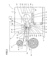
- 1 denotes a portion of a machine for the manufacture of absorbent paddings as utilized in personal hygiene items, particularly nappies (not illustrated)
- the machine 1 comprises a frame 2, and a vertical bulkhead 3 supported by the frame.
- the bottom part of the machine 1 incorporates a conveyor 4 consisting in an endless belt element 5 looped around a plurality of pulleys 6, carried by the bulkhead 3 and rotatable thus about horizontal axes, of which two only are indicated and of which at least one is driven by a motor (not illustrated) in such a way that the belt element 5 can be made to advance in a predetermined feed direction D1.
- the belt element 5 affords a plurality of pockets (not illustrated) distributed uniformly and at a predetermined pitch along the entire developable length of the selfsame element 5, internally of which the aforementioned paddings are fashioned.
- the pulleys 6 and the belt element 5 combine to create an active top branch 7, serving to establish a line L1 along which the paddings are formed and transported, and a return bottom branch 8.
- the machine 1 comprises a station 10, coinciding with an infeed end 9 of the aforementioned line L1, of which the function is to process an absorbent strip material 11.
- the station 10 incorporates a pulp mill 12 of conventional embodiment capable of breaking up the strip 11 up into fibrous particles 13 that will be formed subsequently into absorbent paddings (not illustrated) as they pass along the line L1.
- the absorbent strip material 11 consists in a strip of cellulose.
- the machine 1 also comprises a feed unit 14 by which the strip material 11 is directed into the processing station 10.
- the feed unit 14 is in receipt of a first and a second strip of absorbent material, denoted 15 and 16 respectively, decoiled from respective rolls 17 and 18 in respective directions denoted V1 and V2.
- the strips 15 and 16 decoiling from the rolls 17 and 18 pass along respective first and second paths denoted P1 and P2.
- the feed unit 14 Interposed between the rolls 17 and 18 and the pulp mill 12, the feed unit 14 comprises a plate 19 carrying a first and a second power driven roller, both of conventional type, denoted 20 and 21.
- the plate 19, of rectangular outline, is coupled slidably with two rectilinear ways 22 secured to the vertical bulkhead 3 and extending perpendicular to the frame 2.
- the plate 19 is capable of rectilinear movement on the ways 22, generated through the agency of a conventional actuator indicated schematically in the drawings by a block denoted 23.
- rollers 20 and 21 rotate about respective horizontal axes 20a and 21a disposed substantially normal to the plate 19 and to the viewing plane of figure 1.
- the unit 14 further comprises an idle roller 24 rotatable about an axis 24a disposed parallel to the axes 20a and 21a of the power driven rollers 20 and 21, which is located between the selfsame two rollers 20 and 21 and carried freely by a relative shaft 25 associated immovably with the vertical bulkhead 3.
- the shaft 25 of the idle roller 24 is inserted through a slot 26 located between the two power driven rollers 20 and 21 and extending parallel to the aforementioned rectilinear ways 22, in such a manner that the rectilinear motion of the plate 19 along the ways 22 can be rendered independent of the shaft 25, which remains fixed relative to the vertical bulkhead 3.
- the power driven rollers 20 and 21 function as respective first and second driving members 27 and 28 for the first and second strips 15 and 16.
- the idle roller 24 functions as a guidance and pinch member 29 for the first and second strips 15 and 16.
- conveying elements 31, located between the power driven rollers 20 and 21 and the mill 12, by which the strips 15 and 16 are directed into the mill.
- the feed unit 14 comprises two sensors 32 and 33 located in close proximity respectively to the first power driven roller 20 and to the second power driven roller 21 and serving to detect the presence or absence of the strip 15 and 16 at a point immediately beyond the respective roller 20 or 21.
- the fibrous particles 13 of absorbent material 11 are discharged by the mill 12 into the pockets on the active top branch 7 of the conveyor 4 by way of a duct 34 and with the aid of conventional suction devices (not illustrated) located on the opposite side of the belt element 5.
- the belt element 5 advances along the feed direction D1 and, during its progress, the pockets in which the paddings are formed advance likewise along the relative line L1, passing in succession beneath the duct 34 of the mill 12 from which a layer of fibrous particles 13 generated by processing the absorbent material 11 is deposited into each pocket with the aid of the aforementioned suction means (not illustrated).
- the suction means are able to exert an aspirating action on the fibrous particles 13 by virtue of the fact that the belt element 5 of the conveyor 4 is fashioned from a material permeable to air.
- the first strip 15 is pinched between the first power driven roller 20 and the idle roller 24 and fed thus to the inlet of the mill 12, decoiling from the relative roll 17 in the direction denoted V1.
- the plate 19 occupies a first lowered position T1 in which the first power driven roller 20 and the idle roller 24 are mutually tangential.
- the first power driven roller 20 rotates in the same direction as that of the first roll 17, i.e. the decoiling direction V1, whilst the idle roller 24 rotates in the direction denoted R1 in figure 1, i.e. clockwise.
- the elements of the take-up and feed means 30 assume a first configuration of engagement with the first strip 15, which is thus directed into the mill 12 of the processing station 10, and at the same time of substantial disengagement from the second strip 16, which simply rests against the second power driven roller 21 occupying a standby position T2.
- the sensor 32 located next to the first power driven roller 20 will relay a signal to a monitoring and control unit 35 indicating the end-of-roll condition.
- control unit 35 activates the actuator 23, which will respond by raising the plate 19 in the direction of the arrow denoted F1 so as to distance the first power driven roller 20 from the idle roller 24 and cause the second power driven roller 21, with the leading end of the new strip 16 already in place and occupying the standby position T2, to approach the selfsame idle roller 24.
- the second power driven roller 21 is now set in rotation, causing the second strip 16 to decoil from the second roll 18 in the direction denoted V2 and advance toward the inlet of the mill 12.
- the take-up and feed means 30 are now made to assume a second configuration of engagement with the second strip 16, which is thus directed into the mill 12 of the processing station 10, and at the same time of substantial disengagement from the first strip 15, which is missing momentarily but, as soon as a new roll has been fitted to the machine 1, will be simply rested against the first power driven roller 20 in a position corresponding to the standby position T2 described previously with reference to figure 1.
- the plate 19 carrying the rollers 20 and 21 is fixed in relation to the vertical bulkhead 3 of the machine 1 whereas the idle roller 24 is rendered capable of movement, through the agency of a relative actuator 36 and in a direction perpendicular to the frame 2, between two different positions of engagement respectively with the first power driven roller 20 and with the second power driven roller 21, in which the first strip 15 and the second strip 16 respectively are fed into the mill 12.
- Figure 3 shows the position in which the idle roller 24 is in engagement with the first power driven roller 20.
- the feed unit will comprise suction means of conventional embodiment, not illustrated, by which the leading end of the new strip 15 or 16 is held in the standby position T2 on or near the relative power driven roller 20 or 21.
Landscapes
- Health & Medical Sciences (AREA)
- Engineering & Computer Science (AREA)
- Animal Behavior & Ethology (AREA)
- General Health & Medical Sciences (AREA)
- Biomedical Technology (AREA)
- Heart & Thoracic Surgery (AREA)
- Vascular Medicine (AREA)
- Life Sciences & Earth Sciences (AREA)
- Manufacturing & Machinery (AREA)
- Epidemiology (AREA)
- Public Health (AREA)
- Veterinary Medicine (AREA)
- Absorbent Articles And Supports Therefor (AREA)
- Sewing Machines And Sewing (AREA)
- Auxiliary Devices For And Details Of Packaging Control (AREA)
- Orthopedics, Nursing, And Contraception (AREA)
Applications Claiming Priority (2)
| Application Number | Priority Date | Filing Date | Title |
|---|---|---|---|
| ITBO20010470 | 2001-07-24 | ||
| IT2001BO000470A ITBO20010470A1 (it) | 2001-07-24 | 2001-07-24 | Unita' di alimentazione di materiale in nastro ad una linea per la realizzazione di articoli igienici intimi |
Publications (2)
| Publication Number | Publication Date |
|---|---|
| EP1279389A2 true EP1279389A2 (fr) | 2003-01-29 |
| EP1279389A3 EP1279389A3 (fr) | 2005-07-27 |
Family
ID=11439515
Family Applications (1)
| Application Number | Title | Priority Date | Filing Date |
|---|---|---|---|
| EP02425481A Withdrawn EP1279389A3 (fr) | 2001-07-24 | 2002-07-24 | Unité d'alimentation d'un produit en bande pour une ligne de production d'articles hygiéniques |
Country Status (2)
| Country | Link |
|---|---|
| EP (1) | EP1279389A3 (fr) |
| IT (1) | ITBO20010470A1 (fr) |
Cited By (1)
| Publication number | Priority date | Publication date | Assignee | Title |
|---|---|---|---|---|
| KR100584242B1 (ko) | 2005-11-17 | 2006-05-26 | (주)태봉 | 삽입식 생리대 기초재 제조 장치 |
Family Cites Families (4)
| Publication number | Priority date | Publication date | Assignee | Title |
|---|---|---|---|---|
| CS167015B1 (fr) * | 1973-07-24 | 1976-04-29 | ||
| DE3436217A1 (de) * | 1984-10-03 | 1986-04-03 | Focke & Co (GmbH & Co), 2810 Verden | Verfahren und vorrichtung zum wechseln von bobinen in verbindung mit verpackungsmaschinen |
| JP2773841B2 (ja) * | 1989-06-06 | 1998-07-09 | 株式会社東京自働機械製作所 | 帯状材供給装置の帯状材交換機構 |
| NL8902848A (nl) * | 1989-11-17 | 1991-06-17 | Tevopharm Schiedam Bv | Inrichting voor het continu toevoeren van stukken velvormig materiaal naar een verwerkingsmachine. |
-
2001
- 2001-07-24 IT IT2001BO000470A patent/ITBO20010470A1/it unknown
-
2002
- 2002-07-24 EP EP02425481A patent/EP1279389A3/fr not_active Withdrawn
Non-Patent Citations (1)
| Title |
|---|
| None |
Cited By (1)
| Publication number | Priority date | Publication date | Assignee | Title |
|---|---|---|---|---|
| KR100584242B1 (ko) | 2005-11-17 | 2006-05-26 | (주)태봉 | 삽입식 생리대 기초재 제조 장치 |
Also Published As
| Publication number | Publication date |
|---|---|
| EP1279389A3 (fr) | 2005-07-27 |
| ITBO20010470A1 (it) | 2003-01-24 |
| ITBO20010470A0 (it) | 2001-07-24 |
Similar Documents
| Publication | Publication Date | Title |
|---|---|---|
| US9096405B2 (en) | Defective-workpiece discharging device | |
| US7458540B2 (en) | System and process for controlling the deceleration and acceleration rates of a sheet material in forming absorbent articles | |
| CN105083629A (zh) | 吸收性卫生用品单片自动包装机构 | |
| CA2697786A1 (fr) | Appareillage et methode d'application intermittente de bande continue etirable a une bande continue cible | |
| JP5986842B2 (ja) | 吸収性物品に係る個別包装品の連結品の製造装置、及び製造方法 | |
| ES8505611A1 (es) | Perfeccionamientos en un aparato para cortar y enrollar automaticamente material laminar | |
| CA2297184A1 (fr) | Dispositif et procede pour le transport d'un ruban d'enfilage ou d'une bande de materiau | |
| EP1279389A2 (fr) | Unité d'alimentation d'un produit en bande pour une ligne de production d'articles hygiéniques | |
| JP3715612B2 (ja) | シート出し装置 | |
| EP2986261B1 (fr) | Machine et procédé pour fabriquer des articles hygiéniques absorbants | |
| JP2005218553A (ja) | タオルの自動折り畳み供給装置 | |
| US5244449A (en) | Apparatus for feeding a continuous plastic film | |
| TWI528952B (zh) | Method for discharging the absorbent article | |
| JP3100943B2 (ja) | ニードルマシンの制御装置 | |
| CN104562525B (zh) | 无纺布的体积恢复装置以及体积恢复方法 | |
| GB2142609A (en) | Splicing webs | |
| CN216887366U (zh) | 一种烟包内衬纸驳口在线检测剔除装置及包装机 | |
| CN216884349U (zh) | 一种无料感应自动停机装置 | |
| CH687982A5 (it) | Unità per l'erogazione di materiale in foglio, ad esempio per l'erogazione di fogli di cartone o cartoncino in macchine confezionatrici automatiche. | |
| CN116395477B (zh) | 一种短裤型吸收性物品的制造装置 | |
| US4352468A (en) | Apparatus for the uninterrupted withdrawal of webs from reels of webs which are to be unwound successively | |
| CN220948716U (zh) | 一种带有检测功能的消毒纸巾折叠机 | |
| CN220936933U (zh) | 一种打片装置 | |
| JP2004123353A (ja) | シート体の重ね切断装置 | |
| JP3968570B2 (ja) | 横型製袋充填機 |
Legal Events
| Date | Code | Title | Description |
|---|---|---|---|
| PUAI | Public reference made under article 153(3) epc to a published international application that has entered the european phase |
Free format text: ORIGINAL CODE: 0009012 |
|
| AK | Designated contracting states |
Designated state(s): AT BE BG CH CY CZ DE DK EE ES FI FR GB GR IE IT LI LU MC NL PT SE SK TR |
|
| AX | Request for extension of the european patent |
Extension state: AL LT LV MK RO SI |
|
| PUAL | Search report despatched |
Free format text: ORIGINAL CODE: 0009013 |
|
| AK | Designated contracting states |
Kind code of ref document: A3 Designated state(s): AT BE BG CH CY CZ DE DK EE ES FI FR GB GR IE IT LI LU MC NL PT SE SK TR |
|
| AX | Request for extension of the european patent |
Extension state: AL LT LV MK RO SI |
|
| 17P | Request for examination filed |
Effective date: 20050919 |
|
| AKX | Designation fees paid |
Designated state(s): AT BE BG CH CY CZ DE DK EE ES FI FR GB GR IE IT LI LU MC NL PT SE SK TR |
|
| 17Q | First examination report despatched |
Effective date: 20051130 |
|
| STAA | Information on the status of an ep patent application or granted ep patent |
Free format text: STATUS: THE APPLICATION IS DEEMED TO BE WITHDRAWN |
|
| 18D | Application deemed to be withdrawn |
Effective date: 20150203 |