EP1279436A2 - Behandlung und Zuführung einer Flüssigkeit durch einen Mikrokanal in einem elastischen Substrat durch progressives Quetschen des Mikrokanales - Google Patents
Behandlung und Zuführung einer Flüssigkeit durch einen Mikrokanal in einem elastischen Substrat durch progressives Quetschen des Mikrokanales Download PDFInfo
- Publication number
- EP1279436A2 EP1279436A2 EP02014385A EP02014385A EP1279436A2 EP 1279436 A2 EP1279436 A2 EP 1279436A2 EP 02014385 A EP02014385 A EP 02014385A EP 02014385 A EP02014385 A EP 02014385A EP 1279436 A2 EP1279436 A2 EP 1279436A2
- Authority
- EP
- European Patent Office
- Prior art keywords
- fluid
- microchannel
- substrate
- chemical
- delivering
- Prior art date
- Legal status (The legal status is an assumption and is not a legal conclusion. Google has not performed a legal analysis and makes no representation as to the accuracy of the status listed.)
- Withdrawn
Links
Images








Classifications
-
- G—PHYSICS
- G01—MEASURING; TESTING
- G01N—INVESTIGATING OR ANALYSING MATERIALS BY DETERMINING THEIR CHEMICAL OR PHYSICAL PROPERTIES
- G01N1/00—Sampling; Preparing specimens for investigation
-
- F—MECHANICAL ENGINEERING; LIGHTING; HEATING; WEAPONS; BLASTING
- F04—POSITIVE - DISPLACEMENT MACHINES FOR LIQUIDS; PUMPS FOR LIQUIDS OR ELASTIC FLUIDS
- F04B—POSITIVE-DISPLACEMENT MACHINES FOR LIQUIDS; PUMPS
- F04B43/00—Machines, pumps, or pumping installations having flexible working members
- F04B43/12—Machines, pumps, or pumping installations having flexible working members having peristaltic action
- F04B43/1223—Machines, pumps, or pumping installations having flexible working members having peristaltic action the actuating elements, e.g. rollers, moving in a straight line during squeezing
-
- B—PERFORMING OPERATIONS; TRANSPORTING
- B01—PHYSICAL OR CHEMICAL PROCESSES OR APPARATUS IN GENERAL
- B01L—CHEMICAL OR PHYSICAL LABORATORY APPARATUS FOR GENERAL USE
- B01L3/00—Containers or dishes for laboratory use, e.g. laboratory glassware; Droppers
- B01L3/50—Containers for the purpose of retaining a material to be analysed, e.g. test tubes
- B01L3/502—Containers for the purpose of retaining a material to be analysed, e.g. test tubes with fluid transport, e.g. in multi-compartment structures
- B01L3/5027—Containers for the purpose of retaining a material to be analysed, e.g. test tubes with fluid transport, e.g. in multi-compartment structures by integrated microfluidic structures, i.e. dimensions of channels and chambers are such that surface tension forces are important, e.g. lab-on-a-chip
- B01L3/50273—Containers for the purpose of retaining a material to be analysed, e.g. test tubes with fluid transport, e.g. in multi-compartment structures by integrated microfluidic structures, i.e. dimensions of channels and chambers are such that surface tension forces are important, e.g. lab-on-a-chip characterised by the means or forces applied to move the fluids
-
- B—PERFORMING OPERATIONS; TRANSPORTING
- B01—PHYSICAL OR CHEMICAL PROCESSES OR APPARATUS IN GENERAL
- B01L—CHEMICAL OR PHYSICAL LABORATORY APPARATUS FOR GENERAL USE
- B01L3/00—Containers or dishes for laboratory use, e.g. laboratory glassware; Droppers
- B01L3/50—Containers for the purpose of retaining a material to be analysed, e.g. test tubes
- B01L3/505—Flexible containers without fluid transport within
-
- F—MECHANICAL ENGINEERING; LIGHTING; HEATING; WEAPONS; BLASTING
- F04—POSITIVE - DISPLACEMENT MACHINES FOR LIQUIDS; PUMPS FOR LIQUIDS OR ELASTIC FLUIDS
- F04B—POSITIVE-DISPLACEMENT MACHINES FOR LIQUIDS; PUMPS
- F04B43/00—Machines, pumps, or pumping installations having flexible working members
- F04B43/02—Machines, pumps, or pumping installations having flexible working members having plate-like flexible members, e.g. diaphragms
- F04B43/04—Pumps having electric drive
- F04B43/043—Micropumps
-
- F—MECHANICAL ENGINEERING; LIGHTING; HEATING; WEAPONS; BLASTING
- F04—POSITIVE - DISPLACEMENT MACHINES FOR LIQUIDS; PUMPS FOR LIQUIDS OR ELASTIC FLUIDS
- F04B—POSITIVE-DISPLACEMENT MACHINES FOR LIQUIDS; PUMPS
- F04B43/00—Machines, pumps, or pumping installations having flexible working members
- F04B43/12—Machines, pumps, or pumping installations having flexible working members having peristaltic action
- F04B43/14—Machines, pumps, or pumping installations having flexible working members having peristaltic action having plate-like flexible members
-
- G—PHYSICS
- G01—MEASURING; TESTING
- G01N—INVESTIGATING OR ANALYSING MATERIALS BY DETERMINING THEIR CHEMICAL OR PHYSICAL PROPERTIES
- G01N30/00—Investigating or analysing materials by separation into components using adsorption, absorption or similar phenomena or using ion-exchange, e.g. chromatography or field flow fractionation
- G01N30/02—Column chromatography
- G01N30/26—Conditioning of the fluid carrier; Flow patterns
- G01N30/28—Control of physical parameters of the fluid carrier
- G01N30/32—Control of physical parameters of the fluid carrier of pressure or speed
-
- B—PERFORMING OPERATIONS; TRANSPORTING
- B01—PHYSICAL OR CHEMICAL PROCESSES OR APPARATUS IN GENERAL
- B01L—CHEMICAL OR PHYSICAL LABORATORY APPARATUS FOR GENERAL USE
- B01L2300/00—Additional constructional details
- B01L2300/02—Identification, exchange or storage of information
- B01L2300/025—Displaying results or values with integrated means
- B01L2300/028—Graduation
-
- B—PERFORMING OPERATIONS; TRANSPORTING
- B01—PHYSICAL OR CHEMICAL PROCESSES OR APPARATUS IN GENERAL
- B01L—CHEMICAL OR PHYSICAL LABORATORY APPARATUS FOR GENERAL USE
- B01L2300/00—Additional constructional details
- B01L2300/08—Geometry, shape and general structure
- B01L2300/0809—Geometry, shape and general structure rectangular shaped
- B01L2300/0816—Cards, e.g. flat sample carriers usually with flow in two horizontal directions
-
- B—PERFORMING OPERATIONS; TRANSPORTING
- B01—PHYSICAL OR CHEMICAL PROCESSES OR APPARATUS IN GENERAL
- B01L—CHEMICAL OR PHYSICAL LABORATORY APPARATUS FOR GENERAL USE
- B01L2300/00—Additional constructional details
- B01L2300/08—Geometry, shape and general structure
- B01L2300/0861—Configuration of multiple channels and/or chambers in a single devices
- B01L2300/0867—Multiple inlets and one sample wells, e.g. mixing, dilution
-
- B—PERFORMING OPERATIONS; TRANSPORTING
- B01—PHYSICAL OR CHEMICAL PROCESSES OR APPARATUS IN GENERAL
- B01L—CHEMICAL OR PHYSICAL LABORATORY APPARATUS FOR GENERAL USE
- B01L2400/00—Moving or stopping fluids
- B01L2400/04—Moving fluids with specific forces or mechanical means
- B01L2400/0475—Moving fluids with specific forces or mechanical means specific mechanical means and fluid pressure
- B01L2400/0481—Moving fluids with specific forces or mechanical means specific mechanical means and fluid pressure squeezing of channels or chambers
-
- B—PERFORMING OPERATIONS; TRANSPORTING
- B01—PHYSICAL OR CHEMICAL PROCESSES OR APPARATUS IN GENERAL
- B01L—CHEMICAL OR PHYSICAL LABORATORY APPARATUS FOR GENERAL USE
- B01L3/00—Containers or dishes for laboratory use, e.g. laboratory glassware; Droppers
- B01L3/50—Containers for the purpose of retaining a material to be analysed, e.g. test tubes
- B01L3/502—Containers for the purpose of retaining a material to be analysed, e.g. test tubes with fluid transport, e.g. in multi-compartment structures
- B01L3/5025—Containers for the purpose of retaining a material to be analysed, e.g. test tubes with fluid transport, e.g. in multi-compartment structures for parallel transport of multiple samples
-
- B—PERFORMING OPERATIONS; TRANSPORTING
- B01—PHYSICAL OR CHEMICAL PROCESSES OR APPARATUS IN GENERAL
- B01L—CHEMICAL OR PHYSICAL LABORATORY APPARATUS FOR GENERAL USE
- B01L3/00—Containers or dishes for laboratory use, e.g. laboratory glassware; Droppers
- B01L3/50—Containers for the purpose of retaining a material to be analysed, e.g. test tubes
- B01L3/502—Containers for the purpose of retaining a material to be analysed, e.g. test tubes with fluid transport, e.g. in multi-compartment structures
- B01L3/5027—Containers for the purpose of retaining a material to be analysed, e.g. test tubes with fluid transport, e.g. in multi-compartment structures by integrated microfluidic structures, i.e. dimensions of channels and chambers are such that surface tension forces are important, e.g. lab-on-a-chip
- B01L3/502707—Containers for the purpose of retaining a material to be analysed, e.g. test tubes with fluid transport, e.g. in multi-compartment structures by integrated microfluidic structures, i.e. dimensions of channels and chambers are such that surface tension forces are important, e.g. lab-on-a-chip characterised by the manufacture of the container or its components
-
- G—PHYSICS
- G01—MEASURING; TESTING
- G01N—INVESTIGATING OR ANALYSING MATERIALS BY DETERMINING THEIR CHEMICAL OR PHYSICAL PROPERTIES
- G01N30/00—Investigating or analysing materials by separation into components using adsorption, absorption or similar phenomena or using ion-exchange, e.g. chromatography or field flow fractionation
- G01N30/02—Column chromatography
- G01N30/26—Conditioning of the fluid carrier; Flow patterns
- G01N30/28—Control of physical parameters of the fluid carrier
- G01N30/32—Control of physical parameters of the fluid carrier of pressure or speed
- G01N2030/326—Control of physical parameters of the fluid carrier of pressure or speed pumps
Definitions
- the present invention relates to a method and device for accurately handling and delivering infinitesimal amounts of fluid in an elastic polymeric substrate of microfluidic devices used in chemical and biochemical analyses, syntheses and detection.
- the method and device deliver fluid by applying an external force on the substrate to progressively squeeze a microchannel therein along its length to deliver a desired amount of fluid through the microchannel.
- lab-on-a-chip is a "chemical microprocessor” made by integrating many kinds of devices on a substrate (or chip) having a dimension of several centimeters and made of glass, silicone or plastic using photolithography or micromachining used generally in semiconductor technology.
- the lab-on-a-chip can be used to carry out automated experiments with a high rate, high efficiency and low cost (Kovas, Anal. Chem. 68 (1996) 407A-412A).
- the method for delivering infinitesimal amounts of fluid in a lab-on-a-chip is completely different from conventional methods for delivering ordinary amounts of fluid since the method is used when the amount of the sample is very small and delivery of fluid is carried out through a very small microchannels.
- a conventional method for delivering infinitesimal amounts of fluid in a microchannel uses electric fields.
- the flow of fluid can be controlled by using capillary electro-osmosis generated when a voltage is applied at the both ends of the microchannel filled with fluid without any additional pumps or valves.
- Chemical samples can also be separated and analyzed by using capillary electrophoresis. Therefore, it is possible to create a so-called "small chemistry lab on a chip".
- Devices used in this conventional method are simple and accordingly, this method is used most commonly in the fields of delivering fluids in microchannels such as in a lab-on-a-chip.
- this method is used most commonly in the fields of delivering fluids in microchannels such as in a lab-on-a-chip.
- controlling the delivery of fluid therethrough is quite difficult because accurate application of electric fields is difficult.
- accurate delivery is difficult or impossible when several kinds of solutions are delivered together since the flows of the fluids are affected by the physical properties, such as acidity (pH), ionic strength and viscosity, of the fluid to be delivered.
- the present invention provides a method for delivering various kinds of fluids at a constant rate and/or delivering fluid to a certain position in the microchannel regardless of the physical properties of the fluids to be delivered in microchannels of an elastic polymeric substrate.
- the substrate having microchannels formed therein does not require any additional mechanical devices or complicated structures for accurately delivering the desired fluids.
- the present invention also provides an elastic polymeric substrate having a particular structure with one or more microchannels formed therein for achieving the above method.
- the present invention also provides a device capable of delivering various kinds of fluids at a constant rate or to a certain position in the above elastic polymeric substrate regardless of the physical properties of the fluids.
- Fluid F in a microchannel 22 is delivered by pushing the fluid F in a desired direction (towards the right R in Figure 1A) or by pulling the fluid F to a desired direction (towards the left L in Figure 1B) by a solid structure S applying an external (mechanical) force onto the substrate 20 to squeeze the microchannel 22 therein.
- the squeezed portion is moved in the horizontal direction along the microchannel 22 in the substrate 20 which made of elastic polymeric material.
- substrate and “chip” are used interchangeably to express various structural aspects.
- delivery rate and/or location of infinitesimal amounts of fluid in the microchannel 22 can be accurately controlled by adjusting the traveling rate and/or distance of the portion receiving external force onto the substrate 20 to squeeze the microchannel 22 therein.
- Such controlling can be compared with the function of a pump in an injector.
- an additional tube for connecting to the substrate and an injector is needed.
- the portions receiving fluid, a connection tube and a portion functioning as the pump of the injector can be integrated into a substrate 20.
- the means for applying external force can be moved. Also, an identical effect can be obtained by fixing the location of the means for applying external force while the substrate 20 itself is moved.
- FIG. 2 an example of a device for delivering fluid in the substrate 20 is shown in Figure 2.
- a miniature roller 10 connected to z-axis translational device 38 can be used to apply external (mechanical) force on the microchannel 22 through the substrate 20.
- the roller 10 squeezes the microchannel 22 as it presses the substrate 20 from above.
- a z-axis translational device 38 can have a miniature roller 10 fixed to a x-axis translational elements having a motorized linear actuator 34 with a minimum moving distance of less than about 1 ⁇ m.
- a roller 10 is used as a means for applying external (mechanical) force to the substrate 20 to minimize friction with the substrate 20.
- a lubricant can also be used between the contact surface of the solid structure and the substrate 20 to further reduce friction.
- the means capable of applying external (mechanical) force to the substrate 20 can be operated manually or can be automated by using a motor, a pump, an electromagnet or the like.
- a motor, a pump, an electromagnet or the like When external (mechanical) force is applied, a corresponding restoring force is generated by the elasticity of the polymeric substrate 20.
- a bolt and nut combination in the z-axis translational device 38 can be used to apply force required on the substrate 20.
- a spring, an air pressure piston or an electromagnet may be used to maintain the desired force being applied on the substrate 20.
- the method of pressing the microchannel 22 can be performed by applying external (mechanical) force to a small area on the substrate 20 using a cylinder or a miniature roller as shown in Figures 1 and 2.
- a quantitative delivery of fluid would be difficult since the fluid may sometimes leak out from the portion pressed on the microchannel 22 if a high back pressure within the microchannel 22 is generated when the fluid flows therethrough.
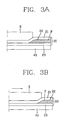
- Figure 3 shows a method for preventing leakage of the fluid in the microchannel 22 by widening the surface area of the substrate 20 on which the microchannel 22 is pressed with external force. It can be seen that a solid structure S contacts a larger area of the substrate 20 in Figure 3 than that when using the roller 10.
- Figure 4 is an example of a method for manufacturing a microchannel chip using PDMS which is a kind of an elastic polymer.
- any type of material can be used as long as it allows progressive squeezing the microchannel.
- rubber, silicone type rubber or polymeric materials such as plastics, having elasticity, can be used.
- methods of making a microchannel in the substrate in addition to a method described above, pressing a flat substrate surface with an embossing mold, a hot embossing process, a manufacturing process using mechanical means, or an engraving process with light or heat energy applying laser energy or other means can be used.
- the substrate in accordance with the present invention does not in itself include a means for delivering fluid, the assembly process of positioning the structure for delivering a fluid in the substrate and the like is not necessary and accordingly, the manufacture of the substrate is easy. Also; since an identical technique for delivering fluid can be applied by using the present invention regardless of the material of the microchannel substrate, the material of the substrate can be changed without any change in the design of a fluid delivery system.
- Figures 5A and 5B show the process of delivering fluid F in the microchannel 22 using a roller 10.
- the fluid injected through the fluid inlet 30 naturally enters into the microchannel 22 by capillary phenomenon or due to the difference of air pressure caused by pressure applying or reducing ( Figure 5A).
- the roller 10 moves along the substrate 20 in the direction of the microchannel 22 while squeezing thereon, the fluid in the microchannel is delivered in proportion to the distance that the roller 10 moves ( Figure 5B).
- a fluid outlet 31 is also provided at the other end of the microchannel 22 to receive the delivered fluid.
- Various types of microchannels 22 can be used according to the volume or flow rate of the fluid to be delivered.
- the volume of the fluid to be delivered in the present invention can be determined by the size of the microchannel 22 and the moving distance of the miniature roller 10.
- the moving rate of the roller 10 is in the range of 1 ⁇ m/sec to 10mm/sec and a width and a depth of a microchannel are about ⁇ m respectively
- the flow rate of the fluid can be adjusted between 0.1 microliters/sec and 1 milliliter/sec.
- the total range of fluid flow rate can be controlled by adjusting the width and depth of the microchannel, and the fluid flow rate within the determined range can be controlled by adjusting the moving rate of the roller.
- a device for delivering fluid can be made as described in Example 1 and Figure 2 using a single microchannel substrate and a process employing such device in an experiment will be described as follows.
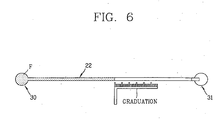
- the single microchannel substrate 20 can have graduations for measuring the moving distance of the fluid formed adjacent to the microchannel 22 on the substrate 20.
- the boundary between the fluid and air in the microchannel 22 can be visually detected with the graduations using a monitor connected with a charge coupled device (hereinafter referred to as "CCD”) camera.
- CCD charge coupled device
- the microchannel 22 in the substrate 20 was filled with red water-soluble ink through the fluid inlet of the substrate 20.
- the miniature roller 10 was then positioned above the microchannel 22 of the substrate 20 using the manual z-axis translational device 38, and moved along the substrate 20 in the direction of the fluid outlet using the linear moving device 34 connected with x-axis translational element so that the microchannel 22 is squeezed along its length. Thereafter, the miniature roller 10 was raised from the substrate 20 using the z-axis translational device 38 after fluid delivery and returned to its original position using the linear moving device 34 connected with the x-axis translational element. The process was repeated three or four times to move the red ink by the graduations of the microchannel substrate 20. Then, as shown in Figure 7, the time required for the fluid to pass between two graduations being a certain distance apart from one another was measured by moving the miniature roller 10 at various rates.
- Figure 8 shows the delivery rates of the red ink when the miniature roller 10 was moved along the substrate 20 at various rates. It shows that the delivery rate of the fluid is exactly proportional to the moving rate of the miniature roller 10.
- the flow rate of the fluid is related to the volume of the inner portion of the microchannel 22 where the roller 10 applies external (mechanical) force whereby, and the widths or depths of a microchannel need not be the same as shown in Figure 5.
- the various conditions of how the solution should be delivered must be changed according to the physical properties of the fluid to thereby accurately adjust the delivery rate of various kinds of fluids.
- various delivery conditions must be considered because the flow rate of electro-osmosis is changed according to the compositions of fluid.
- fluids can be delivered regardless of the physical properties of the fluid since the fluid is pushed or pulled through the microchannel by applying an external (mechanical) force thereon. Further, the delivery rate is determined by the moving rate of the external (mechanical) force being applied on the microchannel. Accordingly, the desired delivery rate can be obtained even if the kind of fluid changes.
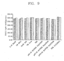
- Figure 9 shows the results of the delivery of various kinds of fluids with a microchannel substrate having a width of about 50 ⁇ m, a depth of about 30 ⁇ m and by setting the rate of the miniature roller at about 200 ⁇ m /sec.
- Figure 9 shows that the flow rate of fluid is the same if the moving rate of the miniature roller 10 is the same, regardless of the kind of the fluid when using the device of the present invention.
- the volume of the fluid can be measured. Because the size of the cross-section of the microchannel 22, namely, the width and the depth of the microchannel 22 are known when the microchannel 22 is formed, the volume of the fluid passing therethrough can be calculated by measuring the length of the microchannel 22 filled with the fluid.
- the volume of the fluid can also be calculated by measuring the delivery distance of the fluid in the microchannel 22 from the front to rear ends of the microchannel 22 (namely, the moving distance of a miniature roller 10) with an imaging instrument such as a CCD camera, or by observing the changes of the intensity of radiation caused by light-scattering at the front and rear ends of the fluid in the microchannel 22 with a light-receiving device after radiating light on a fixed portion in the microchannel 22 with a light-emitting device.
- an imaging instrument such as a CCD camera
- a plurality of microchannels can be manufactured in a substrate since the microchannel substrate preferably has a flat surface.
- a substrate having a plurality of microchannels can be used in various fields of applications, such as in mixing of different solutions, dilution of solutions through mixing, process for chemical and/or binding reactions, dividing a solution into certain volumes, adjusting the delivery direction of the fluid, extraction of a certain substance existing in a solution, and/or separation, purification, concentration and/or titration of chemical compounds.
- Figure 11 is a view showing a method for mixing two kinds of fluids or solutions F1 and F2 in accordance with the present invention.
- the two microchannels 22a and 22b on the substrate are designed to be joined together at an end portion 22c.
- Figure 11A when the fluids are delivered through the respective microchannels 22a and 22b after supplying the fluids F1 and F2 through one end of each microchannel 22a and 22b, the fluids F1 and F2 are mixed at the portion 22c where the microchannels 22a and 22b are joined together ( Figure 11B).
- fluids or solutions can be delivered in two or more microchannels 22a and 22b simultaneously with one roller applying external force on both microchannels 22a and 22b at the same time.
- the fluid mixing ratio can be adjusted by varying the rate of delivering the fluids F1 and F2, varying the ratio of the cross-sectional area (i.e. width x depth) of the microchannels 22a and 22b where the fluids F1 and F2 pass or using both of the above two methods. If fluid F2 is a solvent for fluid F1, fluid F1 can be diluted, and the combined fluid in the microchannel 22c becomes a dilution of fluid F1.
- a reaction can be carried out by mixing in the microchannel 22c.
- Examples of possible reactions include any kind of reaction which can occur in a solution, such as chemical reactions, biochemical reactions between enzymes and the substrates, and binding reactions between a receptor and a ligand, just to name a few.
- the delivery of two kinds of solutions or fluids are mentioned, but the present invention is not limited to such examples as the delivery of two or more solutions can be possible according to the structure of the microchannels.
- the above described delivery is not performed singly but one fluid delivery step can be performed after another fluid delivery step in order or in parallel by using a substrate with a plurality of microchannels and/or fluid delivery portions in the microchannels formed in the substrate.
- the device in accordance with the present invention does not incur damage to the device or result in fluid or solution contamination since the means for delivering fluids or solutions (e.g., a roller progressively squeezing the microchannel) are not in direct contact with the fluids or solutions in the microchannel.
- the method and device of the present invention can also deliver solutions of equal volume regardless of the differences in physical properties of the solutions or fluids. And accordingly, the method in accordance with the present invention can be used as an efficient fluid or solution delivering means in the lab-on-a-chip technology requiring the processes of reacting infinitesimal amounts of chemical and/or biological samples.
- the principle of delivering fluid in accordance with the present invention can be substantially applied to all fields where the lab-on-a-chip technology for handling and/or treating infinitesimal amounts of solutions can be applied.
- the present invention can be applied in its entirety or portions thereof to handle and/or deliver fluids to devices for researching new medicines, compound synthesizers, biochemical analyzers, pre-treatment of samples, instruments for detecting molecules, environmental pollution analyzers, detectors or discriminators for chemical or biochemical weapons, monitoring instruments for chemical or biological processing, medical diagnosing instruments, health examining instruments, cultivators of cells and microbes, and devices for transmitting medicines, just to name a few.
- Figure 12 shows a device capable of injecting/inducting infinitesimal amounts of fluids or solutions in accordance with the present invention.
- a capillary 50 is connected to an end of the microchannel 22 and the other end of the capillary 50 has the form of a pipette tip 60 having a tapered structure.
- the pipette tip 60 structure can be made by "pulling" the capillary.
- the inner diameter of the capillary 50 can be made to be in the range of, for example, 1 ⁇ m to 1mm according to desired applications.
- the inner diameter of the pipette tip structure 60 can be made to be in the range of, for example, 10nm to 100 ⁇ m.
- Possible samples includes, for example, globular fluids, vesicles or cells having a diameter of several micrometers or nanometers, and the present invention can be used to perform reactions by injecting desired fluids or solutions, or to perform sampling by inducting the fluid or solution in the samples.
- the present invention can be used to deliver a certain amount of fluid or solution onto the surface of a solid or into another solution which does not mix well with the solution being delivered.
- the present invention has an advantage in that it can deliver a desired volume of fluid or solution, because the volume of fluid or solution is accurately determined by the moving distance of the external force applying device (e.g., a roller), and by the dimensions of the microchannel itself.
- a method and device for handling by quantitatively delivering fluid or solution in from minute to infinitesimal amounts such as femtoliters up to milliliters is achieved.
- the present invention can be applied to many fields which require handling and/or delivering infinitesimal amounts of fluids or solutions, such as in the fields of searching for new medicines, chemical and biochemical studies, researching in life sciences, medical diagnosing instruments, rapid health examining instruments for home and hospital use, monitoring instruments for chemical or biological processing, portable analyzing instruments for environmental pollutants, and analyzing instruments for detecting or discriminating chemical, biological and radiological weapons, just to name a few.
- the present invention can be applied to a wide variety of fields where the lab-on-a-chip can be applied since the present invention provides a method and device achieving excellent performance in handling and/or delivering fluids yet requiring only a simple structure compared to conventional devices.
Landscapes
- Chemical & Material Sciences (AREA)
- Engineering & Computer Science (AREA)
- Health & Medical Sciences (AREA)
- Analytical Chemistry (AREA)
- General Health & Medical Sciences (AREA)
- Mechanical Engineering (AREA)
- General Engineering & Computer Science (AREA)
- Hematology (AREA)
- Clinical Laboratory Science (AREA)
- Chemical Kinetics & Catalysis (AREA)
- Biochemistry (AREA)
- Life Sciences & Earth Sciences (AREA)
- Physics & Mathematics (AREA)
- General Physics & Mathematics (AREA)
- Immunology (AREA)
- Pathology (AREA)
- Dispersion Chemistry (AREA)
- Automatic Analysis And Handling Materials Therefor (AREA)
- Reciprocating Pumps (AREA)
- Investigating Or Analyzing Non-Biological Materials By The Use Of Chemical Means (AREA)
- Sampling And Sample Adjustment (AREA)
- Physical Or Chemical Processes And Apparatus (AREA)
- Investigating Or Analysing Biological Materials (AREA)
- Feeding, Discharge, Calcimining, Fusing, And Gas-Generation Devices (AREA)
Applications Claiming Priority (2)
| Application Number | Priority Date | Filing Date | Title |
|---|---|---|---|
| KR10-2001-0044513A KR100451154B1 (ko) | 2001-07-24 | 2001-07-24 | 기판 내에서 유체를 조작하는 방법 및 이를 위한 장치 |
| KR2001044513 | 2001-07-24 |
Publications (2)
| Publication Number | Publication Date |
|---|---|
| EP1279436A2 true EP1279436A2 (de) | 2003-01-29 |
| EP1279436A3 EP1279436A3 (de) | 2004-01-02 |
Family
ID=19712474
Family Applications (1)
| Application Number | Title | Priority Date | Filing Date |
|---|---|---|---|
| EP02014385A Withdrawn EP1279436A3 (de) | 2001-07-24 | 2002-06-28 | Behandlung und Zuführung einer Flüssigkeit durch einen Mikrokanal in einem elastischen Substrat durch progressives Quetschen des Mikrokanales |
Country Status (4)
| Country | Link |
|---|---|
| US (1) | US20030025129A1 (de) |
| EP (1) | EP1279436A3 (de) |
| JP (1) | JP3732159B2 (de) |
| KR (1) | KR100451154B1 (de) |
Cited By (9)
| Publication number | Priority date | Publication date | Assignee | Title |
|---|---|---|---|---|
| EP1769849A1 (de) * | 2005-09-27 | 2007-04-04 | Yokogawa Electric Corporation | Kassette für chemische Reaktionen und Verfahren zu ihrer Anwendung |
| GB2405182B (en) * | 2003-08-20 | 2008-01-02 | Micro Chemical Systems Ltd | Fluid dispenser |
| WO2007075289A3 (en) * | 2005-12-27 | 2008-01-10 | Honeywell Int Inc | Fluid free interface for a fluidic analyzer |
| DE102008003822A1 (de) * | 2007-01-17 | 2008-07-24 | Yokogawa Electric Corp., Musashino | Chemische Reaktionskassette |
| WO2008135564A3 (en) * | 2007-05-03 | 2009-05-22 | Clondiag Gmbh | Assays |
| WO2009112594A3 (en) * | 2008-03-14 | 2010-03-04 | Clondiag Gmbh | Assays |
| US8343074B2 (en) | 2004-06-30 | 2013-01-01 | Lifescan Scotland Limited | Fluid handling devices |
| US10753927B2 (en) | 2006-09-22 | 2020-08-25 | ALERE TECHNOLOGIES GmbH | Methods for detecting an analyte |
| CN113164962A (zh) * | 2018-12-05 | 2021-07-23 | 哈美顿博纳图斯股份公司 | 用于弹道排出在纳升范围内的计量总量的液体计量设备、液体计量方法及对此的移液吸头 |
Families Citing this family (35)
| Publication number | Priority date | Publication date | Assignee | Title |
|---|---|---|---|---|
| KR100421359B1 (ko) * | 2001-07-24 | 2004-03-06 | 엘지전자 주식회사 | 탄성 재질의 기판 내에서 유체를 이송하는 방법 및 이를위한 장치 |
| JP3780917B2 (ja) * | 2001-11-22 | 2006-05-31 | 株式会社島津製作所 | 液体クロマトグラフとその溶離液混合装置 |
| KR100618320B1 (ko) * | 2004-09-14 | 2006-08-31 | 삼성전자주식회사 | 유체이동장치 및 이를 구비한 일회용칩 |
| US7727473B2 (en) | 2005-10-19 | 2010-06-01 | Progentech Limited | Cassette for sample preparation |
| KR100773552B1 (ko) | 2006-04-28 | 2007-11-07 | 삼성전자주식회사 | 미세유체 반응 용기, 이의 제조 방법 및, 이를 이용한미세유체 반응 방법 |
| CA2656686A1 (en) | 2006-07-05 | 2008-01-10 | Aida Engineering, Ltd. | Micro passage chip and fluid transferring method |
| US7959876B2 (en) * | 2006-07-17 | 2011-06-14 | Industrial Technology Research Institute | Fluidic device |
| US7794665B2 (en) * | 2006-07-17 | 2010-09-14 | Industrial Technology Research Institute | Fluidic device |
| US20080021364A1 (en) * | 2006-07-17 | 2008-01-24 | Industrial Technology Research Institute | Fluidic device |
| JP4656038B2 (ja) * | 2006-10-16 | 2011-03-23 | パナソニック株式会社 | 静電噴霧方法及びマイクロ流体チップ |
| JP4957260B2 (ja) * | 2007-01-16 | 2012-06-20 | 横河電機株式会社 | 化学反応用カートリッジ及びその使用方法 |
| JP2008272645A (ja) * | 2007-04-27 | 2008-11-13 | Yokogawa Electric Corp | 内容物移送装置および化学処理システム |
| KR101321912B1 (ko) * | 2007-08-28 | 2013-10-30 | 삼성전자주식회사 | 탄성 밸브 및 이를 구비한 미세유동 장치 |
| CN104023834B (zh) | 2011-05-04 | 2016-09-28 | 卢米耐克斯公司 | 用于集成的样品制备、反应和检测的设备与方法 |
| KR101251817B1 (ko) * | 2011-06-15 | 2013-04-09 | 단국대학교 산학협력단 | 미세 유동 장치 |
| WO2013148312A1 (en) * | 2012-03-26 | 2013-10-03 | Alere San Diego, Inc. | Microfluidic pump |
| AU2013334189B2 (en) | 2012-10-24 | 2018-08-02 | Genmark Diagnostics, Inc. | Integrated multiplex target analysis |
| US20140322706A1 (en) | 2012-10-24 | 2014-10-30 | Jon Faiz Kayyem | Integrated multipelx target analysis |
| US10086372B2 (en) * | 2012-12-10 | 2018-10-02 | President And Fellows Of Harvard College | Membrane-based fluid-flow control devices |
| JP6351702B2 (ja) | 2013-03-15 | 2018-07-04 | ジェンマーク ダイアグノスティクス, インコーポレイテッド | 変形可能流体容器を操作するためのシステム、方法、および装置 |
| USD881409S1 (en) | 2013-10-24 | 2020-04-14 | Genmark Diagnostics, Inc. | Biochip cartridge |
| US9498778B2 (en) | 2014-11-11 | 2016-11-22 | Genmark Diagnostics, Inc. | Instrument for processing cartridge for performing assays in a closed sample preparation and reaction system |
| DE102014207238A1 (de) * | 2014-04-15 | 2015-10-15 | Universität Rostock | Einrichtung zum Flüssigkeitstransport durch einen Mikrofluidikkanal |
| DE102014207249A1 (de) * | 2014-04-15 | 2015-10-15 | Universität Rostock | Einrichtung zur Flusssteuerung durch einen Mikrofluidikkanal |
| KR101635459B1 (ko) * | 2014-07-22 | 2016-07-11 | 광운대학교 산학협력단 | 프로그래밍 가능한 마이크로 펌프 |
| US9598722B2 (en) | 2014-11-11 | 2017-03-21 | Genmark Diagnostics, Inc. | Cartridge for performing assays in a closed sample preparation and reaction system |
| US10005080B2 (en) | 2014-11-11 | 2018-06-26 | Genmark Diagnostics, Inc. | Instrument and cartridge for performing assays in a closed sample preparation and reaction system employing electrowetting fluid manipulation |
| KR102564002B1 (ko) | 2017-03-15 | 2023-08-08 | 한국전자통신연구원 | 미세유체 제어 시스템 및 이를 이용한 미세유체 제어 방법 |
| CN109579580A (zh) * | 2017-09-29 | 2019-04-05 | 锐莱热控科技(北京)有限公司 | 一种挤压式微槽道冷板 |
| KR101986432B1 (ko) * | 2017-11-24 | 2019-06-10 | (주) 비비비 | 시료의 흐름을 조절할 수 있는 미세유체분석칩 |
| KR102057329B1 (ko) * | 2018-07-02 | 2020-01-22 | 광운대학교 산학협력단 | 미세유체 위치 제어를 위한 영상처리 기반 제어 시스템 |
| KR102075037B1 (ko) * | 2019-11-14 | 2020-02-07 | 재단법인 대구경북과학기술원 | 유체 제어 장치 및 유체 제어 방법 |
| KR102351481B1 (ko) * | 2019-11-28 | 2022-01-17 | 광운대학교 산학협력단 | 미소유체 반응 관찰용 마이크로 플랫폼 |
| KR102419139B1 (ko) * | 2020-05-07 | 2022-07-11 | 광운대학교 산학협력단 | 미소유체 반응 관찰용 마이크로 플랫폼 |
| KR102749702B1 (ko) * | 2021-11-08 | 2025-01-08 | 한국전자기술연구원 | 마이크로 유체 이동 시스템 |
Family Cites Families (19)
| Publication number | Priority date | Publication date | Assignee | Title |
|---|---|---|---|---|
| US4529106A (en) * | 1982-09-02 | 1985-07-16 | Broadfoot John T | Metering and/or feeding unit for fluid materials |
| US4673657A (en) * | 1983-08-26 | 1987-06-16 | The Regents Of The University Of California | Multiple assay card and system |
| US4982903A (en) * | 1988-06-17 | 1991-01-08 | Ransburg Corporation | Peristaltic voltage block |
| US5460493A (en) * | 1993-11-17 | 1995-10-24 | Baxter International Inc. | Organizer frame for holding an array of flexible tubing in alignment with one or more peristaltic pump rotors |
| US5431307A (en) * | 1994-08-26 | 1995-07-11 | Gencorp Inc. | Dispensing plural components |
| US6234773B1 (en) * | 1994-12-06 | 2001-05-22 | B-Braun Medical, Inc. | Linear peristaltic pump with reshaping fingers interdigitated with pumping elements |
| US5593804A (en) * | 1995-12-05 | 1997-01-14 | Eastman Kodak Company | Test pouch |
| US5705018A (en) * | 1995-12-13 | 1998-01-06 | Hartley; Frank T. | Micromachined peristaltic pump |
| US6720710B1 (en) * | 1996-01-05 | 2004-04-13 | Berkeley Microinstruments, Inc. | Micropump |
| JPH09287571A (ja) * | 1996-04-18 | 1997-11-04 | Fuji Electric Co Ltd | マイクロポンプ |
| US5846061A (en) * | 1996-11-08 | 1998-12-08 | Board Of Trustees Of Michigan State University | Peristaltic metering pump |
| FR2760838B1 (fr) * | 1997-03-13 | 1999-05-21 | Corning Inc | Circuit fluidique integre d'execution d'un processus de preparation ou d'analyse d'un echantillon de matiere fluide, son procede de fabrication et appareil d'exploitation de ce circuit |
| US5947689A (en) * | 1997-05-07 | 1999-09-07 | Scilog, Inc. | Automated, quantitative, system for filtration of liquids having a pump controller |
| WO2001007892A1 (en) * | 1999-07-27 | 2001-02-01 | Esperion Therapeutics, Inc. | Method and device for measurement of cholesterol efflux |
| FR2798867A1 (fr) * | 1999-09-23 | 2001-03-30 | Commissariat Energie Atomique | Dispositif de distribution de fluides dans un microsysteme fluidique |
| US6569674B1 (en) * | 1999-12-15 | 2003-05-27 | Amersham Biosciences Ab | Method and apparatus for performing biological reactions on a substrate surface |
| US6296460B1 (en) * | 2000-03-01 | 2001-10-02 | Steve C. Smith | Rotary cavity pump |
| US6485464B1 (en) * | 2000-04-28 | 2002-11-26 | Medtronic, Inc. | Reduced height implantable drug infusion device |
| US6655934B2 (en) * | 2001-03-21 | 2003-12-02 | Innovent, L.L.C. | Inverted peristaltic pumps and related methods |
-
2001
- 2001-07-24 KR KR10-2001-0044513A patent/KR100451154B1/ko not_active Expired - Fee Related
-
2002
- 2002-06-21 US US10/176,110 patent/US20030025129A1/en not_active Abandoned
- 2002-06-28 EP EP02014385A patent/EP1279436A3/de not_active Withdrawn
- 2002-07-22 JP JP2002212150A patent/JP3732159B2/ja not_active Expired - Fee Related
Cited By (24)
| Publication number | Priority date | Publication date | Assignee | Title |
|---|---|---|---|---|
| GB2405182B (en) * | 2003-08-20 | 2008-01-02 | Micro Chemical Systems Ltd | Fluid dispenser |
| US8343074B2 (en) | 2004-06-30 | 2013-01-01 | Lifescan Scotland Limited | Fluid handling devices |
| EP1914001A1 (de) * | 2005-09-27 | 2008-04-23 | Yokogawa Electric Corporation | Kassette für chemische Reaktionen und Verfahren zu ihrer Verwendung |
| EP1769849A1 (de) * | 2005-09-27 | 2007-04-04 | Yokogawa Electric Corporation | Kassette für chemische Reaktionen und Verfahren zu ihrer Anwendung |
| US7789270B2 (en) | 2005-09-27 | 2010-09-07 | Yokogawa Electric Corporation | Chemical reaction cartridge and method using same |
| CN101389406B (zh) * | 2005-12-27 | 2012-08-15 | 霍尼韦尔国际公司 | 用于流体分析仪的无流体界面 |
| WO2007075289A3 (en) * | 2005-12-27 | 2008-01-10 | Honeywell Int Inc | Fluid free interface for a fluidic analyzer |
| US7485153B2 (en) | 2005-12-27 | 2009-02-03 | Honeywell International Inc. | Fluid free interface for a fluidic analyzer |
| US10753927B2 (en) | 2006-09-22 | 2020-08-25 | ALERE TECHNOLOGIES GmbH | Methods for detecting an analyte |
| US9891226B2 (en) | 2006-09-22 | 2018-02-13 | Clondiag Gmbh | Assays |
| DE102008003822A1 (de) * | 2007-01-17 | 2008-07-24 | Yokogawa Electric Corp., Musashino | Chemische Reaktionskassette |
| US7794669B2 (en) | 2007-01-17 | 2010-09-14 | Yokogawa Electric Corporation | Chemical reaction cartridge |
| WO2008135564A3 (en) * | 2007-05-03 | 2009-05-22 | Clondiag Gmbh | Assays |
| CN101743063B (zh) * | 2007-05-03 | 2012-12-12 | 科隆迪亚戈有限公司 | 分析方法 |
| US8633013B2 (en) | 2007-05-03 | 2014-01-21 | Clondiag Gmbh | Assays |
| AU2008248605B2 (en) * | 2007-05-03 | 2014-02-20 | Clondiag Gmbh | Assays |
| CN101743063A (zh) * | 2007-05-03 | 2010-06-16 | 科隆迪亚戈有限公司 | 分析方法 |
| CN102026725A (zh) * | 2008-03-14 | 2011-04-20 | 科隆迪亚戈有限公司 | 分析 |
| RU2521639C2 (ru) * | 2008-03-14 | 2014-07-10 | Клондиаг Гмбх | Анализы |
| US8906303B2 (en) | 2008-03-14 | 2014-12-09 | Clondiag Gmbh | Assays |
| AP3379A (en) * | 2008-03-14 | 2015-07-31 | Clondiag Gmbh | Assays |
| WO2009112594A3 (en) * | 2008-03-14 | 2010-03-04 | Clondiag Gmbh | Assays |
| CN113164962A (zh) * | 2018-12-05 | 2021-07-23 | 哈美顿博纳图斯股份公司 | 用于弹道排出在纳升范围内的计量总量的液体计量设备、液体计量方法及对此的移液吸头 |
| CN113164962B (zh) * | 2018-12-05 | 2023-06-27 | 哈美顿博纳图斯股份公司 | 液体计量设备和液体计量方法 |
Also Published As
| Publication number | Publication date |
|---|---|
| JP2003130765A (ja) | 2003-05-08 |
| JP3732159B2 (ja) | 2006-01-05 |
| KR20030009857A (ko) | 2003-02-05 |
| US20030025129A1 (en) | 2003-02-06 |
| KR100451154B1 (ko) | 2004-10-02 |
| EP1279436A3 (de) | 2004-01-02 |
Similar Documents
| Publication | Publication Date | Title |
|---|---|---|
| EP1279436A2 (de) | Behandlung und Zuführung einer Flüssigkeit durch einen Mikrokanal in einem elastischen Substrat durch progressives Quetschen des Mikrokanales | |
| Rezk et al. | Uniform mixing in paper-based microfluidic systems using surface acoustic waves | |
| US9086371B2 (en) | Fluidics devices | |
| US9103761B2 (en) | Methods and devices for electronic sensing | |
| EP1322936A2 (de) | Mikrofluidvorrichtungen und verwendungsverfahren | |
| EP1279832B1 (de) | Förderung von Fluiden durch einen Mikrokanal in einem elastischen Substrat durch regelmässiges Zusammendrücken von Teilen des Mikrokanals | |
| US20130087458A1 (en) | Micro-assay chip, assay device using said micro-assay chip and pumping method | |
| JP2003166910A (ja) | 送液機構及び該送液機構を備える分析装置 | |
| Gong et al. | Polydimethylsiloxane-based conducting composites and their applications in microfluidic chip fabrication | |
| EP1320741A1 (de) | Mikrofluidische einrichtungen zur drehmanipulation der fluidischen grenzfläche zwischen mehreren strömungen | |
| CN101176001A (zh) | 用于分析被检体中目标物质的检查芯片和微型综合分析系统 | |
| Zhai et al. | A robust, portable and backflow-free micromixing device based on both capillary-and vacuum-driven flows | |
| Xu et al. | Composite poly (dimethylsiloxane)/glass microfluidic system with an immobilized enzymatic particle-bed reactor and sequential sample injection for chemiluminescence determinations | |
| Grabowska et al. | Architecture and method of fabrication PDMS system for uric acid determination | |
| Song et al. | Polymers for microfluidic chips | |
| Shoji | Micro total analysis system (μTAS) | |
| KR100442680B1 (ko) | 미세 혼합 채널 장치 | |
| Lee et al. | An integrated microfluidic chip for the analysis of biochemical reactions by MALDI mass spectrometry | |
| Traina et al. | Self-powered microfluidic device for the colorimetric detection of lithium via sequential reagent mixing | |
| KR20040091205A (ko) | 다채널 유체 조작 장치 | |
| Ali | Lab-on-a-chip for terrorist weapons management | |
| Yoo et al. | Polydimethylsiloxane microfluidic system with in-channel structure for integrated electrochemical detector | |
| CN117483016A (zh) | 一种模块化管式微流控分析检测装置及检测方法 | |
| Xu | Study of point-of-care microfluidic pumping and blood sample preparation | |
| JP2010160108A (ja) | マイクロ流体デバイスシステム |
Legal Events
| Date | Code | Title | Description |
|---|---|---|---|
| PUAI | Public reference made under article 153(3) epc to a published international application that has entered the european phase |
Free format text: ORIGINAL CODE: 0009012 |
|
| AK | Designated contracting states |
Designated state(s): AT BE CH CY DE DK ES FI FR GB GR IE IT LI LU MC NL PT SE TR |
|
| AX | Request for extension of the european patent |
Extension state: AL LT LV MK RO SI |
|
| PUAL | Search report despatched |
Free format text: ORIGINAL CODE: 0009013 |
|
| AK | Designated contracting states |
Kind code of ref document: A3 Designated state(s): AT BE CH CY DE DK ES FI FR GB GR IE IT LI LU MC NL PT SE TR |
|
| AX | Request for extension of the european patent |
Extension state: AL LT LV MK RO SI |
|
| RIC1 | Information provided on ipc code assigned before grant |
Ipc: 7B 01F 13/00 B Ipc: 7F 04B 19/00 B Ipc: 7F 04B 43/12 B Ipc: 7B 01L 3/00 A |
|
| 17P | Request for examination filed |
Effective date: 20040227 |
|
| AKX | Designation fees paid |
Designated state(s): DE FR GB |
|
| STAA | Information on the status of an ep patent application or granted ep patent |
Free format text: STATUS: THE APPLICATION IS DEEMED TO BE WITHDRAWN |
|
| 18D | Application deemed to be withdrawn |
Effective date: 20080724 |