EP1279449A2 - Méthode et dispositif pour joindre deux objets - Google Patents
Méthode et dispositif pour joindre deux objets Download PDFInfo
- Publication number
- EP1279449A2 EP1279449A2 EP02012247A EP02012247A EP1279449A2 EP 1279449 A2 EP1279449 A2 EP 1279449A2 EP 02012247 A EP02012247 A EP 02012247A EP 02012247 A EP02012247 A EP 02012247A EP 1279449 A2 EP1279449 A2 EP 1279449A2
- Authority
- EP
- European Patent Office
- Prior art keywords
- components
- component
- high pressure
- engraving
- sealing
- Prior art date
- Legal status (The legal status is an assumption and is not a legal conclusion. Google has not performed a legal analysis and makes no representation as to the accuracy of the status listed.)
- Granted
Links
- 238000000034 method Methods 0.000 title claims abstract description 17
- 239000000463 material Substances 0.000 claims abstract description 13
- 239000002131 composite material Substances 0.000 claims abstract description 8
- 238000007789 sealing Methods 0.000 claims description 40
- 125000006850 spacer group Chemical group 0.000 claims description 23
- 239000012530 fluid Substances 0.000 claims description 21
- 230000000712 assembly Effects 0.000 claims description 13
- 238000000429 assembly Methods 0.000 claims description 13
- 150000001875 compounds Chemical class 0.000 claims description 8
- 239000012528 membrane Substances 0.000 claims description 5
- 229920001971 elastomer Polymers 0.000 claims 1
- 239000000806 elastomer Substances 0.000 claims 1
- 230000002093 peripheral effect Effects 0.000 claims 1
- 238000004519 manufacturing process Methods 0.000 description 5
- 230000000694 effects Effects 0.000 description 4
- 239000011343 solid material Substances 0.000 description 4
- 238000003780 insertion Methods 0.000 description 3
- 230000037431 insertion Effects 0.000 description 3
- 230000007774 longterm Effects 0.000 description 3
- 238000010276 construction Methods 0.000 description 2
- 239000004033 plastic Substances 0.000 description 2
- 239000007787 solid Substances 0.000 description 2
- 229910000906 Bronze Inorganic materials 0.000 description 1
- 229910000639 Spring steel Inorganic materials 0.000 description 1
- 229910000831 Steel Inorganic materials 0.000 description 1
- 238000005299 abrasion Methods 0.000 description 1
- 238000004458 analytical method Methods 0.000 description 1
- 125000003118 aryl group Chemical group 0.000 description 1
- 238000005452 bending Methods 0.000 description 1
- 239000010974 bronze Substances 0.000 description 1
- KUNSUQLRTQLHQQ-UHFFFAOYSA-N copper tin Chemical compound [Cu].[Sn] KUNSUQLRTQLHQQ-UHFFFAOYSA-N 0.000 description 1
- 238000005260 corrosion Methods 0.000 description 1
- 230000007797 corrosion Effects 0.000 description 1
- 238000005336 cracking Methods 0.000 description 1
- 230000001419 dependent effect Effects 0.000 description 1
- 238000005516 engineering process Methods 0.000 description 1
- 230000002349 favourable effect Effects 0.000 description 1
- 238000007373 indentation Methods 0.000 description 1
- 238000005304 joining Methods 0.000 description 1
- 229920000642 polymer Polymers 0.000 description 1
- 238000003825 pressing Methods 0.000 description 1
- 238000007493 shaping process Methods 0.000 description 1
- 239000010959 steel Substances 0.000 description 1
- 229920002725 thermoplastic elastomer Polymers 0.000 description 1
Images
Classifications
-
- B—PERFORMING OPERATIONS; TRANSPORTING
- B21—MECHANICAL METAL-WORKING WITHOUT ESSENTIALLY REMOVING MATERIAL; PUNCHING METAL
- B21D—WORKING OR PROCESSING OF SHEET METAL OR METAL TUBES, RODS OR PROFILES WITHOUT ESSENTIALLY REMOVING MATERIAL; PUNCHING METAL
- B21D26/00—Shaping without cutting otherwise than using rigid devices or tools or yieldable or resilient pads, i.e. applying fluid pressure or magnetic forces
- B21D26/02—Shaping without cutting otherwise than using rigid devices or tools or yieldable or resilient pads, i.e. applying fluid pressure or magnetic forces by applying fluid pressure
- B21D26/033—Deforming tubular bodies
- B21D26/047—Mould construction
-
- B—PERFORMING OPERATIONS; TRANSPORTING
- B21—MECHANICAL METAL-WORKING WITHOUT ESSENTIALLY REMOVING MATERIAL; PUNCHING METAL
- B21D—WORKING OR PROCESSING OF SHEET METAL OR METAL TUBES, RODS OR PROFILES WITHOUT ESSENTIALLY REMOVING MATERIAL; PUNCHING METAL
- B21D26/00—Shaping without cutting otherwise than using rigid devices or tools or yieldable or resilient pads, i.e. applying fluid pressure or magnetic forces
- B21D26/02—Shaping without cutting otherwise than using rigid devices or tools or yieldable or resilient pads, i.e. applying fluid pressure or magnetic forces by applying fluid pressure
- B21D26/033—Deforming tubular bodies
-
- B—PERFORMING OPERATIONS; TRANSPORTING
- B21—MECHANICAL METAL-WORKING WITHOUT ESSENTIALLY REMOVING MATERIAL; PUNCHING METAL
- B21D—WORKING OR PROCESSING OF SHEET METAL OR METAL TUBES, RODS OR PROFILES WITHOUT ESSENTIALLY REMOVING MATERIAL; PUNCHING METAL
- B21D39/00—Application of procedures in order to connect objects or parts, e.g. coating with sheet metal otherwise than by plating; Tube expanders
- B21D39/04—Application of procedures in order to connect objects or parts, e.g. coating with sheet metal otherwise than by plating; Tube expanders of tubes with tubes; of tubes with rods
-
- B—PERFORMING OPERATIONS; TRANSPORTING
- B23—MACHINE TOOLS; METAL-WORKING NOT OTHERWISE PROVIDED FOR
- B23P—METAL-WORKING NOT OTHERWISE PROVIDED FOR; COMBINED OPERATIONS; UNIVERSAL MACHINE TOOLS
- B23P11/00—Connecting or disconnecting metal parts or objects by metal-working techniques not otherwise provided for
- B23P11/005—Connecting or disconnecting metal parts or objects by metal-working techniques not otherwise provided for by expanding or crimping
-
- B—PERFORMING OPERATIONS; TRANSPORTING
- B23—MACHINE TOOLS; METAL-WORKING NOT OTHERWISE PROVIDED FOR
- B23P—METAL-WORKING NOT OTHERWISE PROVIDED FOR; COMBINED OPERATIONS; UNIVERSAL MACHINE TOOLS
- B23P11/00—Connecting or disconnecting metal parts or objects by metal-working techniques not otherwise provided for
- B23P11/02—Connecting or disconnecting metal parts or objects by metal-working techniques not otherwise provided for by first expanding and then shrinking or vice versa, e.g. by using pressure fluids; by making force fits
- B23P11/022—Connecting or disconnecting metal parts or objects by metal-working techniques not otherwise provided for by first expanding and then shrinking or vice versa, e.g. by using pressure fluids; by making force fits by using pressure fluids
-
- Y—GENERAL TAGGING OF NEW TECHNOLOGICAL DEVELOPMENTS; GENERAL TAGGING OF CROSS-SECTIONAL TECHNOLOGIES SPANNING OVER SEVERAL SECTIONS OF THE IPC; TECHNICAL SUBJECTS COVERED BY FORMER USPC CROSS-REFERENCE ART COLLECTIONS [XRACs] AND DIGESTS
- Y10—TECHNICAL SUBJECTS COVERED BY FORMER USPC
- Y10T—TECHNICAL SUBJECTS COVERED BY FORMER US CLASSIFICATION
- Y10T29/00—Metal working
- Y10T29/49—Method of mechanical manufacture
- Y10T29/49805—Shaping by direct application of fluent pressure
-
- Y—GENERAL TAGGING OF NEW TECHNOLOGICAL DEVELOPMENTS; GENERAL TAGGING OF CROSS-SECTIONAL TECHNOLOGIES SPANNING OVER SEVERAL SECTIONS OF THE IPC; TECHNICAL SUBJECTS COVERED BY FORMER USPC CROSS-REFERENCE ART COLLECTIONS [XRACs] AND DIGESTS
- Y10—TECHNICAL SUBJECTS COVERED BY FORMER USPC
- Y10T—TECHNICAL SUBJECTS COVERED BY FORMER US CLASSIFICATION
- Y10T29/00—Metal working
- Y10T29/49—Method of mechanical manufacture
- Y10T29/49826—Assembling or joining
- Y10T29/49908—Joining by deforming
-
- Y—GENERAL TAGGING OF NEW TECHNOLOGICAL DEVELOPMENTS; GENERAL TAGGING OF CROSS-SECTIONAL TECHNOLOGIES SPANNING OVER SEVERAL SECTIONS OF THE IPC; TECHNICAL SUBJECTS COVERED BY FORMER USPC CROSS-REFERENCE ART COLLECTIONS [XRACs] AND DIGESTS
- Y10—TECHNICAL SUBJECTS COVERED BY FORMER USPC
- Y10T—TECHNICAL SUBJECTS COVERED BY FORMER US CLASSIFICATION
- Y10T29/00—Metal working
- Y10T29/49—Method of mechanical manufacture
- Y10T29/49826—Assembling or joining
- Y10T29/49908—Joining by deforming
- Y10T29/49925—Inward deformation of aperture or hollow body wall
-
- Y—GENERAL TAGGING OF NEW TECHNOLOGICAL DEVELOPMENTS; GENERAL TAGGING OF CROSS-SECTIONAL TECHNOLOGIES SPANNING OVER SEVERAL SECTIONS OF THE IPC; TECHNICAL SUBJECTS COVERED BY FORMER USPC CROSS-REFERENCE ART COLLECTIONS [XRACs] AND DIGESTS
- Y10—TECHNICAL SUBJECTS COVERED BY FORMER USPC
- Y10T—TECHNICAL SUBJECTS COVERED BY FORMER US CLASSIFICATION
- Y10T29/00—Metal working
- Y10T29/49—Method of mechanical manufacture
- Y10T29/49826—Assembling or joining
- Y10T29/49908—Joining by deforming
- Y10T29/49925—Inward deformation of aperture or hollow body wall
- Y10T29/49934—Inward deformation of aperture or hollow body wall by axially applying force
Definitions
- the invention relates to a method for connecting two components according to the preamble of claim 1 and an apparatus for performing the same according to the preamble of claim. 6
- a generic method or a generic device is known for example from US 3,977,068.
- a tubular component is pushed into a through hole of a plate-shaped component with play, after which an expansion lance is introduced into the tubular member, by means of which the tubular member is so plastically expanded by fluidic internal high pressure that it rests against the inside of the through hole of the plate-shaped component ,
- This is also widened in the area of the hole, but only in the context of material elasticity.
- the hole wall elastically springs back, so that there is an almost permanent detachable press fit between the tubular and the plate-shaped component in the hole area.
- the expansion lance is formed by a rod of a rigid solid material, preferably made of steel, which has an axially extending pressure channel for guiding the pressurized fluid.
- the axial pressure channel is a blind bore and ends shortly before its end in two radially outgoing channels, which have their mouths on the jacket of the rod.
- the orifices are in the use position of the expansion lance within the widened region of the tubular member. This is high pressure resistant axially by two spaced ring seals sealed, which are incorporated in two incorporated on the jacket of the rod annular grooves.
- the inner component Since the expanding lance is inserted into a tubular component and, for reasons of strength, must have a certain minimum cross section dependent on the applied high pressure, the inner component must necessarily also have an inner minimum diameter. The applicability to inner components with a smaller inner diameter is therefore not possible with the known technique. In addition, the requirement that the inner component must be hollow is determined by the necessity of introducing the expansion lance. Due to the limited long-term strength of Aufweitlanze, especially for thinner specimens, a series use of the lance due to the frequent tool change due to the tool wear and the associated downtime leads to a relatively expensive manufacturing process of the joint connection.
- the invention is based on the object, a generic method, or a generic device to the effect that in a relatively simple manner and process reliable components without restriction in terms of minimum size of an inner diameter of the components and in terms of the design of the inner member can be connected together.
- the deforming loading comes from the outside, eliminates the need to introduce a Aufweitlanze in an inner component.
- the dependency of the shaping of the inner component of a minimum cross section of the lance is eliminated.
- the inner components can now be polygonal, tubular, asymmetrical, multiply bent or even made of solid material.
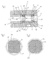
- a forming tool 1 of a device for connecting two components by means of fluidic high pressure is shown, which is solid and integrally formed and has a passage which forms the tool engraving 2.
- the forming tool 1 can also be divided into an upper and a lower die, which has advantages in the accessibility to the components to be joined, in particular when the components are introduced in the sliding assembly in the forming tool 1 and thereby exactly must remain axially and / or radially positioned, provides.
- a circumferential recess 3 is incorporated, which is axially open on one side. The recess 3 accommodates two sealing arrangements 5 and 7, as well as a spacer sleeve 6 spaced from each other.
- the seal assembly 5 is supported, at this axially the spacer sleeve 6 and at this axially again the further seal assembly 7 from.
- the seal assemblies 5 and 7 would be used in axially separate annular grooves of the engraving 2 and a spacer sleeve 6 would be omitted, offers solution shown clear advantages in the usability or interchangeability of the seal assemblies 5 and 7 in case of wear of the seal assemblies or when using different - larger or smaller - sealing arrangements in the case of application change to larger or smaller components or components of other cross-sectional shape.
- the forming tool 1 has a pressure channel 8, which is connected on the one hand to an external fluid high pressure generator and leads from the outside into the sliding composite receiving engraving 2 of the tool 1.
- the orifice 9 of the pressure channel 8 is located at the location of the interference fit to be produced.
- the pressure channel 8 leads in a simple manner through the wall 10 of the spacer sleeve 6, the inside 11 forms the majority of the engraving 2 of the forming tool 1 along the location of the press fit to be produced, which simplifies the design of the forming tool 1 and the compactness of the tool. 1 increased.
- the sliding assembly at the point of the interference fit to be produced can be incorporated into the engraving 2 in the case of the absence of a spacer sleeve 6 or in the inside 11 of the spacer sleeve 6, a circumferential recess into which opens the pressure channel 8 and the runs along the location of the press fit to be produced. This is particularly advantageous if the sliding assembly fits snugly against the engraving 2 or the inside 11 of the spacer sleeve 6.
- the outlet 9 of the pressure channel 8 or said recess is covered for engraving 2 out by an elastic membrane which is attached to the engraving 2 or the inner side 11 of the spacer sleeve 6.
- an elastic membrane which is attached to the engraving 2 or the inner side 11 of the spacer sleeve 6.
- the seal assemblies 5 and 7 include an elastic sealing ring 12 made of a thermoplastic elastomer whose low abrasion during insertion and removal of the sliding assembly of the components guarantees high long-term stability, and on the side facing away from the point of the press fit to be produced, supporting ring 13 from a material of high Shore hardness includes.
- the support ring 13 is made of high pressure resistant material, is radially elastic and has a very high tensile strength in the axial direction.
- As a material for the support ring 13 bronze or a spring steel is conceivable.
- the use of a linear aromatic polymer or a Polyoxylenmethylenplastomer has proven to be particularly favorable in terms of meeting the requirements of the support ring 13.
- the support ring 13 is surrounded by an axially projecting collar 14 of the sealing ring 12, whereby the support ring fixed with bias 13 presses the sealing ring 12 at the location of the collar 14 radially against the wall of the recess 3 and thus the sealing ring 12 an additional grip in the recess 3 gives.
- the sealing ring 12 further comprises a circumferential in the engraving 2 of the forming tool 1 and against the direction of the axial pressure component of the outer component forming high pressure obliquely projecting sealing lip 15 which is axially supported by the support ring 13 to Spaltxtrusionen of the sealing ring 12 in the gap, which exists between the sliding assembly and the engraving 2 outside the high pressure and in the atmospheric pressure prevails to avoid in the fluid high pressure generation and thus to minimize the wear of the sealing ring 12.
- the sealing lip 15 has a smaller outer diameter than the outer diameter of the sliding compound.
- the sealing lip 15 during insertion of the sliding assembly or the individual components in the engraving 2 of the forming tool 1 of the sliding composite or its components bent back so that the sealing ring 12 bears against the outside of the outer component of the sliding compound under prestress and thus applies a sealing effect before the fluid pressure buildup.
- the sealing lip 15 bridges the gap which enlarges during the plastic deformation of the outer component between the inner side 11 of the spacer sleeve 6 and the outer component by elastic springback to its starting position corresponding to the non-use position prior to insertion of the sliding assembly. In this case, advantageously relatively large gaps can be bridged high pressure-tight.
- the sealing ring 12 in the axial direction of the spacer sleeve 6 open notched indentation groove 16 is incorporated, the outer edge of which forms the upper side of the sealing lip 15.
- the annular groove 16 of the sealing lip 15 is given sufficient elasticity to create the best possible to ensure sufficient sealing ability on the outer component of the sliding compound can.
- the depth of the annular groove 16 should not be so large that a risk of cracking of the sealing ring 12 occurs, but be large enough to ensure sufficient elasticity of the sealing lip 15.
- the spacer sleeve 6 has frontally on both sides of a circumferential chamfer 17, via which the pressure channel 8 with the annular groove 16 of the sealing ring 12 is fluidly connectable.
- the sealing lip 15 is additionally acted upon via the annular groove 16 by means of the pressure fluid, so that it is pressed with high force against the outer component of the sliding composite to form complete high-pressure tightness.
- the inclination of the sealing lip 15 is advantageous since a radial component of the fluid high pressure can act on the lip 15.
- end ring 19 is arranged, which rests axially supporting the seal assembly 7.
- the device further includes an axial punch 20, by means of which the end ring 19 can be acted upon.
- the axial punch 20 is inserted into a cross-sectional widened bore 21 adjoining the open end 18 of the recess 3 and holds the sealing arrangements 5 and 7 and the spacer sleeve 6 in position against the high pressure during the production of the joint in which it supports the closing ring 19.
- the end ring 19 as a single part is required due to the tapered bore outlet and bridges the associated with the outlet distance between the seal assembly 7 and the end 22 of the Axialstempels 20.
- the seal assemblies 5 and 7 may be integrated into a sealing module, which is insertable into a circumferential recess of the engraving 2 of the forming tool 1.
- the module further includes in addition to the seal assemblies 5 and 7, the spacer sleeve 6, the 5 and 7, the two seal assemblies spaced from each other, and a support for the seal assemblies 5.7 and the spacer sleeve 6.
- This is possible in a simple manner, the inventive device tailor made for different applications convert. In this case, only pre-assembled modules must be present, which can then be quickly removed from the forming tool 1 and replaced. Thus, the seal assemblies 5 and 7 and the spacer sleeve 6 can be replaced as a whole and need not be removed and attached individually.
- Another component of the module may also be the end ring 19, since this must be matched to the diameter of the seal assembly 7 and therefore also has to be replaced with replacement of this arrangement.
- the method for connecting two components by means of fluidic high pressure proceeds as follows. Two components, an inner 23 and an outer 24, will be pushed towards each other in a suitable manner, so that an overlap or even a complete overlap of the two components 23,24 is achieved, which are loosely connected together in the sliding seat (FIG. 2).
- the inner member 23 may be hollow, but here is made of solid material and has a polygonal cross section, wherein the corners are connected to each other by a curvature 25 of the solid material. This curvature 25 allows the subsequent pressing of the outer member 24 is a gentle investment and simultaneously prevents a component and connection damaging notch effect.
- the component 23 may alternatively have any other shape.
- the component 24 is cylindrical here, but may also have other hollow cross-sectional shapes.
- the sliding assembly can be made outside of the forming tool 1 and then inserted into the forming tool 1 - or inserted in split tool 1 -werden. It is also conceivable to accomplish the sliding assembly only in the forming tool 1, wherein it is structurally necessary to be able to insert the individual components 23 and 24 from both sides of the forming tool 1 into its engraving 2.
- the introduction of the sliding assembly in the engraving 2 can also be done with closed forming tool 1, ie, when the axial punch 20 inserted into the bore 21 or is screwed and rests against the end ring 19 frontally.
- a fluidic high pressure is applied, in which the external fluid high pressure generator is actuated and a pressurized fluid via the pressure channel 8 leads to the sliding assembly between the seal assemblies 5 and 7.
- the pressurized fluid is then stretched until a forming pressure is reached at which the outer component 24 of the sliding assembly, whose material has a lower yield strength than that of the inner component 23, plastically deformed such that it virtually shrinks onto the inner component 23.
- the forming pressure is just so high that the inner member 23 is only elastically deformed, that is compressed.
- the high pressure is now released, whereupon the elastically compressed inner component 23 and the plastically deformed outer component 24 elastically spring back.
- the inner part 23 springs back by a larger amount than the outer part 24.
- an equilibrium state is formed, in which the component 24 under radial tensile and the component 23 is under compressive stress. This results in a continuous surface pressure on the parting surface and thus a strong joining bond.
- the components 23 and 24 are thus frictionally engaged with one another in a very strong press fit at least at a plurality of circumferential points and due to the rotational asymmetry of the inner component 23 shown in a form-fitting manner, so that they are fixed to one another both in the axial and in the radial direction (FIG. 3).
- the outer member 24 is acted upon directly by the pressurized fluid, the high pressure can be transferred to the component 24 by means of a attached to the engraving 2 or the spacer sleeve 6 membrane.
- the outer member 24 with the inner member 23 is not necessarily pressed over the entire overlap region of the sliding compound but depending on the dimensions of the distance of the seal assemblies 5 and 7 to each other only over an axial portion of the overlap region.
- the invention can find its application, for example in the body shop in shell structures of vehicles, steering columns or bumper bending vehicles.
Landscapes
- Engineering & Computer Science (AREA)
- Mechanical Engineering (AREA)
- Physics & Mathematics (AREA)
- Fluid Mechanics (AREA)
- Shaping Metal By Deep-Drawing, Or The Like (AREA)
- Automatic Assembly (AREA)
- Quick-Acting Or Multi-Walled Pipe Joints (AREA)
- Pressure Welding/Diffusion-Bonding (AREA)
- Pistons, Piston Rings, And Cylinders (AREA)
- Sealing Devices (AREA)
Priority Applications (1)
| Application Number | Priority Date | Filing Date | Title |
|---|---|---|---|
| EP04014286A EP1457276B1 (fr) | 2001-07-13 | 2002-06-04 | Dispositif pour joindre deux objets |
Applications Claiming Priority (2)
| Application Number | Priority Date | Filing Date | Title |
|---|---|---|---|
| DE10134086A DE10134086C2 (de) | 2001-07-13 | 2001-07-13 | Verfahren und Vorrichtung zum Verbinden zweier Bauteile |
| DE10134086 | 2001-07-13 |
Related Child Applications (1)
| Application Number | Title | Priority Date | Filing Date |
|---|---|---|---|
| EP04014286A Division EP1457276B1 (fr) | 2001-07-13 | 2002-06-04 | Dispositif pour joindre deux objets |
Publications (3)
| Publication Number | Publication Date |
|---|---|
| EP1279449A2 true EP1279449A2 (fr) | 2003-01-29 |
| EP1279449A3 EP1279449A3 (fr) | 2003-07-23 |
| EP1279449B1 EP1279449B1 (fr) | 2005-02-23 |
Family
ID=7691667
Family Applications (2)
| Application Number | Title | Priority Date | Filing Date |
|---|---|---|---|
| EP02012247A Expired - Lifetime EP1279449B1 (fr) | 2001-07-13 | 2002-06-04 | Méthode pour joindre deux objets |
| EP04014286A Expired - Lifetime EP1457276B1 (fr) | 2001-07-13 | 2002-06-04 | Dispositif pour joindre deux objets |
Family Applications After (1)
| Application Number | Title | Priority Date | Filing Date |
|---|---|---|---|
| EP04014286A Expired - Lifetime EP1457276B1 (fr) | 2001-07-13 | 2002-06-04 | Dispositif pour joindre deux objets |
Country Status (4)
| Country | Link |
|---|---|
| US (2) | US7055238B2 (fr) |
| EP (2) | EP1279449B1 (fr) |
| DE (3) | DE10134086C2 (fr) |
| ES (2) | ES2247573T3 (fr) |
Cited By (2)
| Publication number | Priority date | Publication date | Assignee | Title |
|---|---|---|---|---|
| EP1498217B1 (fr) * | 2003-07-17 | 2008-05-28 | DGS Druckguss Systeme AG | Procédé de fabrication d'un élément fonctionnel à construction légère et élément fonctionnel à construction légère |
| CN105057476A (zh) * | 2015-07-17 | 2015-11-18 | 苏州金牛精密机械有限公司 | 气管对接口自动对接机 |
Families Citing this family (9)
| Publication number | Priority date | Publication date | Assignee | Title |
|---|---|---|---|---|
| GB0214515D0 (en) * | 2002-06-24 | 2002-08-07 | Crane John Uk Ltd | Seals |
| DE10347101B4 (de) * | 2003-10-10 | 2005-12-22 | Daimlerchrysler Ag | Drehfeste Verbindung |
| ES2351128B1 (es) * | 2008-11-26 | 2011-11-28 | Bsh Electrodomesticos España, S.A. | Tambor y máquina para el cuidado de la ropa. |
| AU2011308673B2 (en) * | 2010-09-30 | 2014-11-20 | Hendrickson Usa, L.L.C. | Brake system component axle mount |
| DE102010060686B4 (de) * | 2010-11-19 | 2015-02-26 | Fraunhofer-Gesellschaft zur Förderung der angewandten Forschung e.V. (FHG) | Verfahren und Komponentensatz zur Herstellung eines rohrförmigen Bauteils, insbesondere einer gebauten Nockenwelle |
| DE102014005415B4 (de) * | 2014-04-14 | 2020-02-13 | Sew-Eurodrive Gmbh & Co Kg | Lageranordnung für ein Getriebe und Verfahren zum Einstellen der Vorspannung einer Lageranordnung |
| JP6773649B2 (ja) | 2014-10-06 | 2020-10-21 | ジョン クレーン インコーポレーテッド | ハイドロパッド面プロファイルを有するメカニカルシール |
| DE102017220424B4 (de) | 2017-11-16 | 2021-01-14 | Vitesco Technologies GmbH | Werkzeug und Verfahren zur Anordnung eines Stators in ein Gehäuse |
| CN111082280B (zh) * | 2019-12-27 | 2021-05-25 | 嘉兴君权自动化设备有限公司 | 用于电缆端头的输送剪断压接一体化装置 |
Family Cites Families (14)
| Publication number | Priority date | Publication date | Assignee | Title |
|---|---|---|---|---|
| US3417456A (en) * | 1966-09-30 | 1968-12-24 | Army Usa | Method for pulse forming |
| US3889354A (en) * | 1968-03-29 | 1975-06-17 | Sintokogio Ltd | Method of forming a crimped tube joint |
| US3977068A (en) * | 1975-07-14 | 1976-08-31 | Balcke-Durr Aktiengesellschaft | Device and method for expansion-swaging tubes into the bores of a tube plate |
| US4557128A (en) * | 1982-01-27 | 1985-12-10 | Costabile John J | Apparatus for producing a bulge in thin metal material |
| DE58909685D1 (de) * | 1988-05-25 | 1996-07-11 | Nussbaum & Co Ag R | Pressverbindungsanordnung, Armatur und Verfahren zur Herstellung |
| US5235734A (en) * | 1991-11-04 | 1993-08-17 | Itt Corporation | Collapsible steering shaft apparatus and method of making same |
| DE4406726A1 (de) * | 1994-03-02 | 1995-09-07 | Balcke Duerr Ag | Verfahren und Vorrichtung zur Herstellung von Verbundrohren |
| US5829137A (en) * | 1995-04-03 | 1998-11-03 | Grassi; John R. | Method for manufacturing wheels |
| US5983478A (en) * | 1996-09-18 | 1999-11-16 | The Boeing Company | Tube forming on an end fitting |
| DE19830623B4 (de) * | 1998-07-09 | 2005-04-28 | Forschungsges Umformtechnik | Verfahren und Vorrichtung zur Umformung von Werkstücken, insbesondere von Hohlkörpern, durch Einwirkung eines Druckmediums |
| US6386532B1 (en) * | 2001-03-12 | 2002-05-14 | The Boeing Company | Clamp squeeze apparatus and method |
| WO2002103156A1 (fr) * | 2001-06-15 | 2002-12-27 | Tesco Corporation | Procede de preparation d'un tubage de puits pour son installation |
| US7363945B2 (en) * | 2002-09-24 | 2008-04-29 | The Boeing Co. | Low chamfer angled torque tube end fitting with elongated overflow groove |
| US7007362B2 (en) * | 2003-04-29 | 2006-03-07 | Torque-Tractiontechnologies, Inc. | Method of forming a slip joint |
-
2001
- 2001-07-13 DE DE10134086A patent/DE10134086C2/de not_active Expired - Fee Related
-
2002
- 2002-06-04 DE DE50202305T patent/DE50202305D1/de not_active Expired - Fee Related
- 2002-06-04 EP EP02012247A patent/EP1279449B1/fr not_active Expired - Lifetime
- 2002-06-04 ES ES04014286T patent/ES2247573T3/es not_active Expired - Lifetime
- 2002-06-04 ES ES02012247T patent/ES2238056T3/es not_active Expired - Lifetime
- 2002-06-04 EP EP04014286A patent/EP1457276B1/fr not_active Expired - Lifetime
- 2002-06-04 DE DE50203992T patent/DE50203992D1/de not_active Expired - Fee Related
- 2002-07-12 US US10/193,704 patent/US7055238B2/en not_active Expired - Fee Related
-
2006
- 2006-03-07 US US11/368,468 patent/US20060144109A1/en not_active Abandoned
Cited By (2)
| Publication number | Priority date | Publication date | Assignee | Title |
|---|---|---|---|---|
| EP1498217B1 (fr) * | 2003-07-17 | 2008-05-28 | DGS Druckguss Systeme AG | Procédé de fabrication d'un élément fonctionnel à construction légère et élément fonctionnel à construction légère |
| CN105057476A (zh) * | 2015-07-17 | 2015-11-18 | 苏州金牛精密机械有限公司 | 气管对接口自动对接机 |
Also Published As
| Publication number | Publication date |
|---|---|
| US20060144109A1 (en) | 2006-07-06 |
| ES2247573T3 (es) | 2006-03-01 |
| DE50203992D1 (de) | 2005-09-22 |
| ES2238056T3 (es) | 2005-08-16 |
| DE50202305D1 (de) | 2005-03-31 |
| EP1457276B1 (fr) | 2005-08-17 |
| US7055238B2 (en) | 2006-06-06 |
| EP1279449A3 (fr) | 2003-07-23 |
| EP1279449B1 (fr) | 2005-02-23 |
| US20030024095A1 (en) | 2003-02-06 |
| DE10134086A1 (de) | 2003-01-30 |
| EP1457276A1 (fr) | 2004-09-15 |
| DE10134086C2 (de) | 2003-05-15 |
Similar Documents
| Publication | Publication Date | Title |
|---|---|---|
| DE9216369U1 (de) | Preßwerkzeug | |
| DE102010023855A1 (de) | Verfahren zur Herstellung eines Ventilgehäuses | |
| EP1279449B1 (fr) | Méthode pour joindre deux objets | |
| DE3226868A1 (de) | Dauerhaft dichte gewindelose rohrverbindung | |
| DE19833006B4 (de) | Verfahren und Vorrichtung zur Herstellung rohrförmiger gebogener Hohlkörper durch Innenhochdruckumformen | |
| DE102013109880B4 (de) | Reibungsarmer Endennachschub beim Innenhochdruckumformen | |
| DE10230284B4 (de) | Verfahren und Vorrichtung zur Befestigung von Bauteilen an umfänglich geschlossensn Hohlprofilen | |
| DE19751408C2 (de) | Verfahren und Vorrichtung zur Herstellung eines Integralgehäuses für Hydrolenkung | |
| DE10048005B4 (de) | Vorrichtung zum Verbinden mindestens zweier flächiger, übereinander liegender Bauteile | |
| DE102005036419B4 (de) | Vorrichtung zur Herstellung ausgebauchter Hohlprofile, insbesondere von Gasgeneratorgehäusen für Airbageinrichtungen | |
| DE19533828C2 (de) | Vorrichtung zum Innenhochdruckumformen von rohrförmigen Rohlingen | |
| EP1793155B1 (fr) | Collier de tuyau, notamment collier perce-tuyau | |
| DE10359834B3 (de) | Vorrichtung zum Durchtrennen eines Hohlprofils | |
| EP3350047B1 (fr) | Cylindre combiné de frein de service et frein à resssort, et procécé pour sa fabrication | |
| DE10358493B4 (de) | Vorrichtung zum Innenhochdruckumformen | |
| DE10356269B3 (de) | Vorrichtung zur Abdichtung des Spaltes zwischen sich relativ zueinander bewegenden Werkzeugteilen gegen das Eindringen von flüssigen oder teilflüssigen metallischen Werkstoffen in diesen Spalt | |
| DE102007017030B3 (de) | Verfahren und Vorrichtung zum Herstellen eines Innenhochdruckumformteils | |
| EP1657007B1 (fr) | Procédé de formage de pièces | |
| WO2000060267A1 (fr) | Dispositif pour l'assemblage de tubes | |
| DE102010012452B4 (de) | Verfahren und Vorrichtung zum lokalen Fügen und/oder zum lokalen Umformen von Hohlprofilen mittels Hochdruck | |
| DE10343135B4 (de) | Verfahren zur Herstellung eines umfänglich geschlossenen Hohlprofiles | |
| EP0343624A2 (fr) | Procédé et dispositif pour déformer des produits comme profils creux, tubes etc. | |
| EP1626825A1 (fr) | Procede de fabrication d'un profile creux pourvu d'un couvercle de fermeture a son extremite et console de cric | |
| DE2026420A1 (de) | Verfahren zur festen, insbesondere abgedichteten Verbindung eines Hohlkörpers mit einem den Hohlkörper allseitig umschließenden Außenteil | |
| DE102004024575A1 (de) | Vorrichtung zum partiellen Aufweiten eines Hohlprofils |
Legal Events
| Date | Code | Title | Description |
|---|---|---|---|
| PUAI | Public reference made under article 153(3) epc to a published international application that has entered the european phase |
Free format text: ORIGINAL CODE: 0009012 |
|
| AK | Designated contracting states |
Designated state(s): AT BE CH CY DE DK ES FI FR GB GR IE IT LI LU MC NL PT SE TR |
|
| AX | Request for extension of the european patent |
Extension state: AL LT LV MK RO SI |
|
| PUAL | Search report despatched |
Free format text: ORIGINAL CODE: 0009013 |
|
| AK | Designated contracting states |
Designated state(s): AT BE CH CY DE DK ES FI FR GB GR IE IT LI LU MC NL PT SE TR |
|
| AX | Request for extension of the european patent |
Extension state: AL LT LV MK RO SI |
|
| 17P | Request for examination filed |
Effective date: 20030705 |
|
| 17Q | First examination report despatched |
Effective date: 20031110 |
|
| AKX | Designation fees paid |
Designated state(s): DE ES FR GB IT SE |
|
| RTI1 | Title (correction) |
Free format text: METHOD FOR CONNECTING TWO OBJECTS |
|
| GRAP | Despatch of communication of intention to grant a patent |
Free format text: ORIGINAL CODE: EPIDOSNIGR1 |
|
| GRAS | Grant fee paid |
Free format text: ORIGINAL CODE: EPIDOSNIGR3 |
|
| GRAA | (expected) grant |
Free format text: ORIGINAL CODE: 0009210 |
|
| AK | Designated contracting states |
Kind code of ref document: B1 Designated state(s): DE ES FR GB IT SE |
|
| REG | Reference to a national code |
Ref country code: GB Ref legal event code: FG4D Free format text: NOT ENGLISH |
|
| REF | Corresponds to: |
Ref document number: 50202305 Country of ref document: DE Date of ref document: 20050331 Kind code of ref document: P |
|
| GBT | Gb: translation of ep patent filed (gb section 77(6)(a)/1977) |
Effective date: 20050330 |
|
| REG | Reference to a national code |
Ref country code: SE Ref legal event code: TRGR |
|
| REG | Reference to a national code |
Ref country code: ES Ref legal event code: FG2A Ref document number: 2238056 Country of ref document: ES Kind code of ref document: T3 |
|
| PLBE | No opposition filed within time limit |
Free format text: ORIGINAL CODE: 0009261 |
|
| STAA | Information on the status of an ep patent application or granted ep patent |
Free format text: STATUS: NO OPPOSITION FILED WITHIN TIME LIMIT |
|
| ET | Fr: translation filed | ||
| 26N | No opposition filed |
Effective date: 20051124 |
|
| PGFP | Annual fee paid to national office [announced via postgrant information from national office to epo] |
Ref country code: ES Payment date: 20080627 Year of fee payment: 7 |
|
| PGFP | Annual fee paid to national office [announced via postgrant information from national office to epo] |
Ref country code: IT Payment date: 20080621 Year of fee payment: 7 |
|
| PGFP | Annual fee paid to national office [announced via postgrant information from national office to epo] |
Ref country code: DE Payment date: 20080620 Year of fee payment: 7 Ref country code: SE Payment date: 20080612 Year of fee payment: 7 |
|
| PGFP | Annual fee paid to national office [announced via postgrant information from national office to epo] |
Ref country code: FR Payment date: 20080613 Year of fee payment: 7 |
|
| PGFP | Annual fee paid to national office [announced via postgrant information from national office to epo] |
Ref country code: GB Payment date: 20080620 Year of fee payment: 7 |
|
| REG | Reference to a national code |
Ref country code: FR Ref legal event code: CA Ref country code: FR Ref legal event code: CD |
|
| GBPC | Gb: european patent ceased through non-payment of renewal fee |
Effective date: 20090604 |
|
| REG | Reference to a national code |
Ref country code: FR Ref legal event code: ST Effective date: 20100226 |
|
| PG25 | Lapsed in a contracting state [announced via postgrant information from national office to epo] |
Ref country code: FR Free format text: LAPSE BECAUSE OF NON-PAYMENT OF DUE FEES Effective date: 20090630 |
|
| PG25 | Lapsed in a contracting state [announced via postgrant information from national office to epo] |
Ref country code: GB Free format text: LAPSE BECAUSE OF NON-PAYMENT OF DUE FEES Effective date: 20090604 |
|
| PG25 | Lapsed in a contracting state [announced via postgrant information from national office to epo] |
Ref country code: DE Free format text: LAPSE BECAUSE OF NON-PAYMENT OF DUE FEES Effective date: 20100101 |
|
| REG | Reference to a national code |
Ref country code: ES Ref legal event code: FD2A Effective date: 20090605 |
|
| PG25 | Lapsed in a contracting state [announced via postgrant information from national office to epo] |
Ref country code: ES Free format text: LAPSE BECAUSE OF NON-PAYMENT OF DUE FEES Effective date: 20090605 |
|
| PG25 | Lapsed in a contracting state [announced via postgrant information from national office to epo] |
Ref country code: IT Free format text: LAPSE BECAUSE OF NON-PAYMENT OF DUE FEES Effective date: 20090604 |
|
| PG25 | Lapsed in a contracting state [announced via postgrant information from national office to epo] |
Ref country code: SE Free format text: LAPSE BECAUSE OF NON-PAYMENT OF DUE FEES Effective date: 20090605 |