EP1279805B1 - Refroidisseur de l'air de charge aéroréfrigérée - Google Patents
Refroidisseur de l'air de charge aéroréfrigérée Download PDFInfo
- Publication number
- EP1279805B1 EP1279805B1 EP02012975A EP02012975A EP1279805B1 EP 1279805 B1 EP1279805 B1 EP 1279805B1 EP 02012975 A EP02012975 A EP 02012975A EP 02012975 A EP02012975 A EP 02012975A EP 1279805 B1 EP1279805 B1 EP 1279805B1
- Authority
- EP
- European Patent Office
- Prior art keywords
- air
- cooler
- charge
- flat tubes
- cooling
- Prior art date
- Legal status (The legal status is an assumption and is not a legal conclusion. Google has not performed a legal analysis and makes no representation as to the accuracy of the status listed.)
- Expired - Lifetime
Links
- 238000001816 cooling Methods 0.000 claims abstract description 48
- 239000002826 coolant Substances 0.000 claims abstract description 12
- 229910052782 aluminium Inorganic materials 0.000 claims abstract description 4
- XAGFODPZIPBFFR-UHFFFAOYSA-N aluminium Chemical compound [Al] XAGFODPZIPBFFR-UHFFFAOYSA-N 0.000 claims abstract description 3
- 239000000110 cooling liquid Substances 0.000 claims description 14
- 239000004411 aluminium Substances 0.000 claims 2
- 229910000831 Steel Inorganic materials 0.000 claims 1
- 239000000470 constituent Substances 0.000 claims 1
- 238000007789 sealing Methods 0.000 claims 1
- 239000010959 steel Substances 0.000 claims 1
- 239000012530 fluid Substances 0.000 abstract 1
- 239000003570 air Substances 0.000 description 53
- 238000002485 combustion reaction Methods 0.000 description 5
- XLYOFNOQVPJJNP-UHFFFAOYSA-N water Substances O XLYOFNOQVPJJNP-UHFFFAOYSA-N 0.000 description 4
- 230000000694 effects Effects 0.000 description 3
- 238000013461 design Methods 0.000 description 2
- 238000011835 investigation Methods 0.000 description 2
- 229910000679 solder Inorganic materials 0.000 description 2
- 238000012549 training Methods 0.000 description 2
- 238000012546 transfer Methods 0.000 description 2
- 240000001439 Opuntia Species 0.000 description 1
- 235000004727 Opuntia ficus indica Nutrition 0.000 description 1
- 230000006978 adaptation Effects 0.000 description 1
- 238000004378 air conditioning Methods 0.000 description 1
- 239000012080 ambient air Substances 0.000 description 1
- 239000011248 coating agent Substances 0.000 description 1
- 238000000576 coating method Methods 0.000 description 1
- 238000011161 development Methods 0.000 description 1
- 230000018109 developmental process Effects 0.000 description 1
- 238000002474 experimental method Methods 0.000 description 1
- 230000006870 function Effects 0.000 description 1
- 238000000265 homogenisation Methods 0.000 description 1
- 238000009434 installation Methods 0.000 description 1
- 239000007788 liquid Substances 0.000 description 1
- 239000000463 material Substances 0.000 description 1
- 238000005259 measurement Methods 0.000 description 1
- 230000008450 motivation Effects 0.000 description 1
- 238000005457 optimization Methods 0.000 description 1
- 238000005057 refrigeration Methods 0.000 description 1
- 238000005476 soldering Methods 0.000 description 1
- 238000012360 testing method Methods 0.000 description 1
- 238000003466 welding Methods 0.000 description 1
Images


Classifications
-
- F—MECHANICAL ENGINEERING; LIGHTING; HEATING; WEAPONS; BLASTING
- F28—HEAT EXCHANGE IN GENERAL
- F28F—DETAILS OF HEAT-EXCHANGE AND HEAT-TRANSFER APPARATUS, OF GENERAL APPLICATION
- F28F9/00—Casings; Header boxes; Auxiliary supports for elements; Auxiliary members within casings
- F28F9/02—Header boxes; End plates
- F28F9/0234—Header boxes; End plates having a second heat exchanger disposed there within, e.g. oil cooler
-
- F—MECHANICAL ENGINEERING; LIGHTING; HEATING; WEAPONS; BLASTING
- F02—COMBUSTION ENGINES; HOT-GAS OR COMBUSTION-PRODUCT ENGINE PLANTS
- F02B—INTERNAL-COMBUSTION PISTON ENGINES; COMBUSTION ENGINES IN GENERAL
- F02B29/00—Engines characterised by provision for charging or scavenging not provided for in groups F02B25/00, F02B27/00 or F02B33/00 - F02B39/00; Details thereof
- F02B29/04—Cooling of air intake supply
- F02B29/0406—Layout of the intake air cooling or coolant circuit
- F02B29/0412—Multiple heat exchangers arranged in parallel or in series
-
- F—MECHANICAL ENGINEERING; LIGHTING; HEATING; WEAPONS; BLASTING
- F02—COMBUSTION ENGINES; HOT-GAS OR COMBUSTION-PRODUCT ENGINE PLANTS
- F02B—INTERNAL-COMBUSTION PISTON ENGINES; COMBUSTION ENGINES IN GENERAL
- F02B29/00—Engines characterised by provision for charging or scavenging not provided for in groups F02B25/00, F02B27/00 or F02B33/00 - F02B39/00; Details thereof
- F02B29/04—Cooling of air intake supply
- F02B29/045—Constructional details of the heat exchangers, e.g. pipes, plates, ribs, insulation, materials, or manufacturing and assembly
- F02B29/0456—Air cooled heat exchangers
-
- F—MECHANICAL ENGINEERING; LIGHTING; HEATING; WEAPONS; BLASTING
- F02—COMBUSTION ENGINES; HOT-GAS OR COMBUSTION-PRODUCT ENGINE PLANTS
- F02B—INTERNAL-COMBUSTION PISTON ENGINES; COMBUSTION ENGINES IN GENERAL
- F02B29/00—Engines characterised by provision for charging or scavenging not provided for in groups F02B25/00, F02B27/00 or F02B33/00 - F02B39/00; Details thereof
- F02B29/04—Cooling of air intake supply
- F02B29/045—Constructional details of the heat exchangers, e.g. pipes, plates, ribs, insulation, materials, or manufacturing and assembly
- F02B29/0462—Liquid cooled heat exchangers
-
- F—MECHANICAL ENGINEERING; LIGHTING; HEATING; WEAPONS; BLASTING
- F28—HEAT EXCHANGE IN GENERAL
- F28D—HEAT-EXCHANGE APPARATUS, NOT PROVIDED FOR IN ANOTHER SUBCLASS, IN WHICH THE HEAT-EXCHANGE MEDIA DO NOT COME INTO DIRECT CONTACT
- F28D1/00—Heat-exchange apparatus having stationary conduit assemblies for one heat-exchange medium only, the media being in contact with different sides of the conduit wall, in which the other heat-exchange medium is a large body of fluid, e.g. domestic or motor car radiators
- F28D1/02—Heat-exchange apparatus having stationary conduit assemblies for one heat-exchange medium only, the media being in contact with different sides of the conduit wall, in which the other heat-exchange medium is a large body of fluid, e.g. domestic or motor car radiators with heat-exchange conduits immersed in the body of fluid
- F28D1/04—Heat-exchange apparatus having stationary conduit assemblies for one heat-exchange medium only, the media being in contact with different sides of the conduit wall, in which the other heat-exchange medium is a large body of fluid, e.g. domestic or motor car radiators with heat-exchange conduits immersed in the body of fluid with tubular conduits
- F28D1/0408—Multi-circuit heat exchangers, e.g. integrating different heat exchange sections in the same unit or heat exchangers for more than two fluids
- F28D1/0461—Combination of different types of heat exchanger, e.g. radiator combined with tube-and-shell heat exchanger; Arrangement of conduits for heat exchange between at least two media and for heat exchange between at least one medium and the large body of fluid
-
- F—MECHANICAL ENGINEERING; LIGHTING; HEATING; WEAPONS; BLASTING
- F28—HEAT EXCHANGE IN GENERAL
- F28F—DETAILS OF HEAT-EXCHANGE AND HEAT-TRANSFER APPARATUS, OF GENERAL APPLICATION
- F28F9/00—Casings; Header boxes; Auxiliary supports for elements; Auxiliary members within casings
- F28F9/02—Header boxes; End plates
-
- F—MECHANICAL ENGINEERING; LIGHTING; HEATING; WEAPONS; BLASTING
- F02—COMBUSTION ENGINES; HOT-GAS OR COMBUSTION-PRODUCT ENGINE PLANTS
- F02B—INTERNAL-COMBUSTION PISTON ENGINES; COMBUSTION ENGINES IN GENERAL
- F02B29/00—Engines characterised by provision for charging or scavenging not provided for in groups F02B25/00, F02B27/00 or F02B33/00 - F02B39/00; Details thereof
- F02B29/04—Cooling of air intake supply
- F02B29/0493—Controlling the air charge temperature
-
- F—MECHANICAL ENGINEERING; LIGHTING; HEATING; WEAPONS; BLASTING
- F28—HEAT EXCHANGE IN GENERAL
- F28D—HEAT-EXCHANGE APPARATUS, NOT PROVIDED FOR IN ANOTHER SUBCLASS, IN WHICH THE HEAT-EXCHANGE MEDIA DO NOT COME INTO DIRECT CONTACT
- F28D21/00—Heat-exchange apparatus not covered by any of the groups F28D1/00 - F28D20/00
- F28D2021/0019—Other heat exchangers for particular applications; Heat exchange systems not otherwise provided for
- F28D2021/008—Other heat exchangers for particular applications; Heat exchange systems not otherwise provided for for vehicles
- F28D2021/0082—Charged air coolers
-
- Y—GENERAL TAGGING OF NEW TECHNOLOGICAL DEVELOPMENTS; GENERAL TAGGING OF CROSS-SECTIONAL TECHNOLOGIES SPANNING OVER SEVERAL SECTIONS OF THE IPC; TECHNICAL SUBJECTS COVERED BY FORMER USPC CROSS-REFERENCE ART COLLECTIONS [XRACs] AND DIGESTS
- Y02—TECHNOLOGIES OR APPLICATIONS FOR MITIGATION OR ADAPTATION AGAINST CLIMATE CHANGE
- Y02T—CLIMATE CHANGE MITIGATION TECHNOLOGIES RELATED TO TRANSPORTATION
- Y02T10/00—Road transport of goods or passengers
- Y02T10/10—Internal combustion engine [ICE] based vehicles
- Y02T10/12—Improving ICE efficiencies
Definitions
- the invention relates to an air-cooled intercooler for motor vehicles, consisting of two opposite, a large and a small cross-section having manifolds, which are connected by means of one or more rows of flat tubes having inner inserts, wherein between the flat tubes heat exchange elements are arranged, through which the Cooling air flows through and together with the flat tubes form the cooling network and wherein in at least one of the collecting tanks, a second heat exchanger is arranged, flows around the tubes of the charge air and flowed through by cooling liquid.
- the above features have to be regarded as basically for heat exchangers and also for air-cooled intercoolers.
- the intercooler corresponds for example to that from the document DE 32 00 688 A1 , which was already registered in 1982.
- the second heat exchanger consists of a feed line arranged in the inlet collecting box and a discharge line arranged in the outlet header for a cooling liquid. From the inflow and outflow duct, ducts or flat pipes branch off at regular intervals, which are arranged over their entire length and width in heat exchanging contact with the flat side of the flat tubes for the charge air. Depending on the load condition of the internal combustion engine, the cooling of the charge air thus takes place as required by means of cooling air and by means of the cooling liquid of the internal combustion engine.
- the second heat exchanger is a water-cooled oil cooler, which are arranged in the water tank of a water / air cooler, as for example in the DE 198 20 412 A1 was shown.
- the second heat exchanger is a water cooled condenser for the air conditioning system of the vehicle, which is arranged in the collecting box of a water / air cooler, as for example in EP 678 661 B1 has happened.
- the motivation for the training described consistently throughout is to use the cooling ability of the engine coolant as possible in the smallest space to satisfy other cooling requirements than engine cooling alone.
- the object of the invention is to provide air-cooled charge air cooler, for cooling charge air with a much higher inlet temperature, available with simple, inexpensive means a lower temperature of the charge air at the outlet of the charge air cooler, without the required space for the intercooler essential gets bigger.
- the cooling liquid is used for precooling the charge air in a arranged in the inlet header of the intercooler precooler. Because the inlet temperature of the charge air was reduced by the precooler in the inlet header, the outlet temperature of the charge air at the outlet was reduced as well.
- the training according to the invention provides several welcome side effects.
- the existing channels in the pre-cooler for the charge air ensure a homogenization of the flow in the flat tubes of the air-cooled cooling system, whereby overloading individual flat tubes are avoided.
- the temperature difference between the cooling air and the charge air entering the flat tubes was reduced by the pre-cooling, so that there will no longer be such strong stresses and material breaks caused thereby.
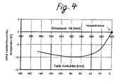
- the cooling capacity of the intercooler was increased in the same size room, whereby the requirements of commercial vehicle manufacturers was met. This was achieved in particular by limiting the depth of the precooler to approximately 25-200 mm, because, as has been shown by test and measurement series, a further increase in the depth of the precooler no longer leads to a corresponding reduction in the size of the air-cooled cooling network. due to the lower temperature gradient. In addition, a noticeably higher pressure loss of the charge air occurs.
- the intercooler 1 and the pre-cooler 10 which is arranged in its inlet collecting box 4 , are made entirely of aluminum, of course, apart from the fact that - as in the embodiment shown - the pre-cooler 10 in Inlet collecting box 4 is mechanically fastened by Anschraubflansche 16 , for which purpose suitable seals 26 are used.
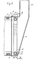
- the Indian Fig. 1 overhead inlet collecting box 4 is substantially larger than the lower outlet collection box 5 to accommodate the precooler 10 in itself.
- the air-cooled cooling network has been reduced in its dimension Hk , so that the space required for the intercooler 1 has remained about the same, compared with a charge air cooler without precooling.
- Both headers 4 and 5 have been manufactured as Aluminiumgußzeugnis.
- the air-cooled cooling network is assembled from flat tubes 6 and corrugated ribs 8 , wherein the corrugated fins 8 rest against the flat sides 32 of the flat tubes 6 .
- the flat tubes 6 are inner inserts. 7 Thereafter, the ends of the flat tubes 6 are inserted into corresponding openings 9 in the tube sheets 12 . Since the parts have a suitable solder coating, the so-connected cooling network can be soldered in a soldering oven.
- the cooling network has only a single row of flat tubes 6 . ( Fig. 3 In other examples, not shown, several rows are arranged side by side.
- the precooler 10 consisting of flat tubes 11 and corrugated fins 20 is assembled.
- the precooler 10 has two tubular collecting chambers 14 , 15 .
- the flat tubes 11 are relatively close to the strin lakeen ends 31 zoom in, like the Fig. 3 shows, moreover, a representation of the large cross-section 2 of the inlet header 4 , which is almost completely filled by the precooler 10 .
- the small cross section 3 should run perpendicular to it, as in the Fig. 1 shown.
- the flat tubes 11 therefore extend slightly beyond the distance between the two collection spaces 14 , 15 .
- the flat tubes 11 of the precooler 10 may each be two half-shells, which are joined together to form a flat tube 11 .
- the collecting chambers 14 , 15 may be formed from drawn from the half-shells cups, wherein the cups of the half-shells at the edge with just such on the adjacent half-shell of the next flat tube 11 are soldered.
- drawn or welded flat tubes 11 which are perforated at the ends, in which case the collecting spaces 14 , 15 can be formed by inserted rings corresponding to the holes - or else by slotted tubes.
- the types described belong to the prior art and are familiar to the expert, for example, for oil cooler.
- the preassembled precoolers are also completely soldered.
- two openings 17 are introduced into the wall 18 of the inlet header 4 .
- Each of these openings 17 receives a arranged on the collecting spaces 14 , 15 connecting piece 16 .
- the connecting pieces 16 are screwed into the openings 17 , wherein previously a suitable seal 26 has been interposed, which also from the Fig. 3 can be seen.
- the connecting pieces 16 are then fastened by means of nuts 27 in the openings 17 .
- the connecting pieces 16 have been welded in the openings 17 .
- the inlet header 4 and the outlet header 5 are connected to the tubesheets 12 by welding.
- Fig. 2 the corresponding weld 19 has been drawn.
- the approximately 300 ° C hot charge air flows through without significant deflection, according to the Fig. 1 in the entry collection box 4 drawn arrow 44 , first the channels 30 ( Fig. 3 ) of the pre-cooler 10 and then, after it was cooled down in the pre-cooler 10 by the liquid coolant of the internal combustion engine, not shown, which has a temperature of about 100 ° C, the pre-cooled charge air enters the flat tubes 6 of the air-cooled cooling network to ambient air until to be cooled to about 60 ° C.
- the channels 30 of the precooler 30 cross the flat sides 32 of the flat tubes 6 , (FIG. Fig.
- the pre-cooler 10 should be sized about 25 to 200 mm. The optimum is between 40 and 120 mm. It has been found that pre-cooler 10 with greater depth, under the given conditions (commercial vehicles), their Effect can not unfold as desired. In particular, a further depression does not result in an equivalent reduction in the height Hk of the air-cooled cooling network.
- the outer channel 30 which is disposed between the wall 18 of the collecting tank 4 and the first flat tube 11 of the precooler 10 , also in this channel 30 is a corrugated fin 20.
- This outer channel 30 may be slightly wider than the other channels 30 for assembly reasons.
- the inlet collecting box 4 has a charge air inlet 60 of considerable dimensions and a wall inclined towards the cooling network, which directs the charge air to the pre-cooler 10 or its channels 30 . From the air-cooled cooling system of the charge air cooler 1 , only the outer corrugated fins 8 and 6 flat tubes were drawn. They extend, of course, over the entire length, which, in contrast to DE 32 00 688 , on each flat tube 6 for the charge air in each case a corrugated fin 8 follows for the cooling air.
Landscapes
- Engineering & Computer Science (AREA)
- Physics & Mathematics (AREA)
- Thermal Sciences (AREA)
- Mechanical Engineering (AREA)
- General Engineering & Computer Science (AREA)
- Chemical & Material Sciences (AREA)
- Combustion & Propulsion (AREA)
- Heat-Exchange Devices With Radiators And Conduit Assemblies (AREA)
- Fuel Cell (AREA)
Claims (10)
- Refroidisseur d'air de charge (1) aéroréfrigéré, pour véhicules automobiles, constitué de deux caisses collectrices (4 ; 5) opposées présentant une grande et une petite section transversale (2 ; 3), qui sont connectées au moyen d'une ou de plusieurs rangées de tubes plats (6) qui présentent des inserts intérieurs (7), entre les tubes plats (6) étant disposés des éléments d'échange thermique (8) à travers lesquels circule l'air de refroidissement et qui forment conjointement avec les tubes plats (6) le réseau de refroidissement, dans au moins l'une des caisses collectrices étant disposé un deuxième échangeur de chaleur (10) dont les tubes sont entourés par la circulation de l'air de charge et qui sont traversés par le liquide de refroidissement,
caractérisé en ce que
dans la caisse collectrice d'entrée (4) du refroidisseur d'air de charge (1) constitué entièrement d'aluminium, est disposé un prérefroidisseur d'air de charge (10) de telle sorte qu'il remplisse au moins pratiquement complètement la grande section transversale (2) de la caisse collectrice d'entrée (4), de sorte qu'au moins pratiquement tout le flux de l'air de charge doive traverser le prérefroidisseur (10), le prérefroidisseur (10) étant complètement brasé et présentant des tubes plats (11) pour le liquide de refroidissement ainsi que des canaux (30) disposés entre eux et garnis d'ailettes (20) pour l'air de charge, la profondeur (40) des canaux (30) garnis d'ailettes étant comprise entre environ 25 et 200 mm et en ce que dans le réseau de refroidissement, chaque tube plat (6) pour l'air de charge prérefroidi est suivi d'un élément d'échange thermique (8) (ailette ondulée) pour l'air de refroidissement, et les ailettes ondulées (8) sont brasées aux côtés plats (32) des tubes plats (6). - Refroidisseur d'air de charge aéroréfrigéré selon la revendication 1, caractérisé en ce que le refroidisseur d'air de charge (1) possède des plaques à tubes (12) dans les ouvertures desquelles débouchent les extrémités des tubes plats (6), notamment y sont brasées, et les caisses collectrices (4 ; 5) sont soudées avec les plaques à tubes (12).
- Refroidisseur d'air de charge aéroréfrigéré selon la revendication 1 et la revendication 2, caractérisé en ce que les canaux (30) garnis d'ailettes (20) pour l'air de charge dans le prérefroidisseur (10) s'étendent en coupant les côtés plats (32) des tubes plats (6) du réseau de refroidissement et la profondeur des canaux (30) est de préférence comprise entre 40 et 120 mm.
- Refroidisseur d'air de charge aéroréfrigéré selon l'une quelconque des revendications précédentes, caractérisé en ce que les canaux parallèles (30) pour l'air de charge dans le prérefroidisseur (10) sont disposés dans une même direction (44) que les tubes plats (6) du réseau de refroidissement de sorte que l'air de charge puisse s'écouler sans déviation notoire à travers le prérefroidisseur (10) et les tubes plats (6) et en ce que les tubes plats (11) pour le liquide de refroidissement s'étendent transversalement à cette direction ou dans la direction longitudinale de la caisse collectrice d'entrée (4).
- Refroidisseur d'air de charge aéroréfrigéré selon l'une quelconque des revendications précédentes, caractérisé en ce que le prérefroidisseur (10) présente deux espaces collecteurs tubulaires (14 ; 15) pour le liquide de refroidissement, qui sont connectés au moyen des tubes plats parallèles (11), une tubulure de raccordement (16) étant prévue à chaque extrémité des espaces collecteurs (14, 15) pour être reliée et montée de manière hermétique et détachable dans chaque ouverture associée (17) de la paroi (18) de la caisse collectrice d'entrée (4) .
- Refroidisseur d'air de charge aéroréfrigéré selon l'une quelconque des revendications 1 à 4, caractérisé en ce que le prérefroidisseur (10) présente deux espaces collecteurs tubulaires (14 ; 15) pour le liquide de refroidissement, qui sont connectés au moyen des tubes plats parallèles (11), une tubulure de raccordement (16) étant prévue à chaque extrémité des espaces collecteurs (14, 15), laquelle est soudée dans une ouverture associée (17) de la paroi (18) de la caisse collectrice d'entrée (4).
- Refroidisseur d'air de charge aéroréfrigéré selon l'une quelconque des revendications précédentes, caractérisé en ce que le prérefroidisseur (10) est disposé de préférence approximativement parallèlement à la plaque à tubes (12) et se compose d'acier spécial ou d'aluminium.
- Refroidisseur d'air de charge aéroréfrigéré selon l'une quelconque des revendications précédentes, caractérisé en ce que la caisse collectrice d'entrée (4) est nettement plus grande que la caisse collectrice de sortie (5).
- Refroidisseur d'air de charge aéroréfrigéré selon l'une quelconque des revendications précédentes, caractérisé en ce que le refroidisseur d'air de charge fait partie d'une installation de refroidissement en forme de caisse, et est disposé dans celle-ci de telle sorte que ses caisses collectrices (4, 5) constituent avec les caisses collectrices de refroidisseurs adjacents à chaque fois un bord de l'installation de refroidissement.
- Refroidisseur d'air de charge aéroréfrigéré selon la revendication 1 et la revendication 9, caractérisé en ce qu'entre la caisse collectrice d'entrée (4) du refroidisseur d'air de charge (1) et la caisse collectrice adjacente du refroidisseur d'air de charge, sont prévues des ouvertures d'écoulement avec des inserts, afin de guider une partie du liquide de refroidissement hors de la caisse collectrice du refroidisseur à liquide de refroidissement à travers le prérefroidisseur (10) dans la caisse collectrice d'entrée (4) du refroidisseur d'air de charge (1).
Applications Claiming Priority (2)
| Application Number | Priority Date | Filing Date | Title |
|---|---|---|---|
| DE10136861 | 2001-07-27 | ||
| DE10136861A DE10136861A1 (de) | 2001-07-27 | 2001-07-27 | Luftgekühlter Ladeluftkühler |
Publications (3)
| Publication Number | Publication Date |
|---|---|
| EP1279805A2 EP1279805A2 (fr) | 2003-01-29 |
| EP1279805A3 EP1279805A3 (fr) | 2004-01-07 |
| EP1279805B1 true EP1279805B1 (fr) | 2008-06-04 |
Family
ID=7693436
Family Applications (1)
| Application Number | Title | Priority Date | Filing Date |
|---|---|---|---|
| EP02012975A Expired - Lifetime EP1279805B1 (fr) | 2001-07-27 | 2002-06-12 | Refroidisseur de l'air de charge aéroréfrigérée |
Country Status (4)
| Country | Link |
|---|---|
| US (1) | US6755158B2 (fr) |
| EP (1) | EP1279805B1 (fr) |
| AT (1) | ATE397716T1 (fr) |
| DE (2) | DE10136861A1 (fr) |
Cited By (1)
| Publication number | Priority date | Publication date | Assignee | Title |
|---|---|---|---|---|
| DE102017107134A1 (de) | 2017-04-03 | 2018-10-04 | Dr. Ing. H.C. F. Porsche Aktiengesellschaft | Wärmetauscher für Hochtemperatur-Anwendung, insbesondere Ladeluftkühler |
Families Citing this family (33)
| Publication number | Priority date | Publication date | Assignee | Title |
|---|---|---|---|---|
| DE10120483A1 (de) * | 2001-04-25 | 2002-10-31 | Modine Mfg Co | Anordnung zur Kühlung |
| FR2852678B1 (fr) * | 2003-03-21 | 2005-07-15 | Valeo Thermique Moteur Sa | Systeme de refroidissement a basse temperature d'un equipement, notamment d'un equipement de vehicule automobile, et echangeurs de chaleur associes |
| DE102004013682A1 (de) | 2003-03-26 | 2004-12-16 | Behr Industrietechnik Gmbh & Co. Kg | Wärmeübertrager, insbesondere Luft/Luft-Kühler |
| DE102004018000A1 (de) * | 2004-04-14 | 2005-11-10 | Dr.Ing.H.C. F. Porsche Ag | Ladeluftkühler |
| US7165537B2 (en) * | 2004-11-10 | 2007-01-23 | Honeywell International Inc. | Charge air cooler |
| DE102004056592A1 (de) * | 2004-11-23 | 2006-05-24 | Behr Gmbh & Co. Kg | Niedertemperaturkühlmittelkühler |
| SE528198C2 (sv) * | 2005-02-21 | 2006-09-26 | Scania Cv Ab | Laddluftkylare |
| DE102005042315A1 (de) * | 2005-09-06 | 2007-03-08 | Behr Gmbh & Co. Kg | Kühlmittelkühler, insbesondere für ein Kraftfahrzeug |
| JP4640288B2 (ja) * | 2005-12-09 | 2011-03-02 | 株式会社デンソー | インタークーラ |
| EP1849989A1 (fr) | 2006-04-26 | 2007-10-31 | Daf Trucks N.V. | Conduite d'interconnexion d'un compresseur et d'un refroidisseur intermédiaire |
| DE102006032205A1 (de) * | 2006-07-12 | 2008-01-17 | Modine Manufacturing Co., Racine | Wärmetauscher mit Kupplungsanschluss und Kupplungsanschluss |
| US20080041556A1 (en) * | 2006-08-18 | 2008-02-21 | Modine Manufacutring Company | Stacked/bar plate charge air cooler including inlet and outlet tanks |
| US8985198B2 (en) | 2006-08-18 | 2015-03-24 | Modine Manufacturing Company | Stacked/bar plate charge air cooler including inlet and outlet tanks |
| SE530583C2 (sv) * | 2006-11-29 | 2008-07-08 | Scania Cv Ab | Kylararrangemang hos ett fordon |
| JP5292695B2 (ja) * | 2007-01-09 | 2013-09-18 | 富士通株式会社 | 配線接続装置 |
| US8225852B2 (en) * | 2008-04-30 | 2012-07-24 | Dana Canada Corporation | Heat exchanger using air and liquid as coolants |
| JP5029547B2 (ja) * | 2008-09-15 | 2012-09-19 | 株式会社デンソー | 吸気冷却システム |
| WO2010079796A1 (fr) | 2009-01-09 | 2010-07-15 | カルソニックカンセイ株式会社 | Échangeur de chaleur combiné |
| DE102010011372A1 (de) | 2009-04-17 | 2010-10-21 | Behr Gmbh & Co. Kg | Ladeluftkanal für einen Verbrennungsmotor |
| FR2947872B1 (fr) * | 2009-07-10 | 2011-10-21 | Peugeot Citroen Automobiles Sa | Systeme de pilotage de la temperature des gaz de suralimentation d'un moteur thermique |
| DE102009039569A1 (de) | 2009-09-01 | 2011-03-03 | Behr Gmbh & Co. Kg | Gaskühler für einen Verbrennungsmotor |
| DE102011077623A1 (de) | 2011-06-16 | 2012-12-20 | Behr Gmbh & Co. Kg | Vorrichtung zur Ladeluftkühlung in einem Kraftfahrzeug |
| FR2997487B1 (fr) * | 2012-10-26 | 2018-07-27 | Valeo Systemes Thermiques | Boite collectrice pour echangeur de chaleur, notamment refroidisseur d'air de suralimentation de moteur de vehicule automobile |
| KR101438608B1 (ko) * | 2012-12-13 | 2014-09-05 | 현대자동차 주식회사 | 차량용 쿨링모듈 |
| DE112014001893T5 (de) | 2013-05-10 | 2016-01-07 | Modine Manufacturing Company | Abgaswärmetauscher und Verfahren |
| CN104975936A (zh) * | 2014-04-04 | 2015-10-14 | 泰安鼎鑫冷却器有限公司 | 一种水空混合式中冷器 |
| AU2015280652B2 (en) | 2014-06-26 | 2017-12-14 | Exxonmobil Upstream Research Company | Pre-cooler for air-cooled heat exchangers |
| CN105587399A (zh) * | 2014-10-21 | 2016-05-18 | 陕西重型汽车有限公司 | 横流式中冷器及该车辆发动机冷却系统 |
| US10046251B2 (en) | 2014-11-17 | 2018-08-14 | Exxonmobil Upstream Research Company | Liquid collection system |
| DE102016006127B4 (de) | 2015-06-08 | 2022-12-29 | Modine Manufacturing Company | Ladeluftkühler und Verfahren |
| US10352278B2 (en) * | 2016-08-19 | 2019-07-16 | Ge Global Sourcing Llc | Method and systems for an exhaust gas recirculation cooler including two sections |
| DE102018106936A1 (de) * | 2018-03-23 | 2019-09-26 | Hanon Systems | Ladeluftkühler aus einem flüssigkeitsgekühlten Vorkühler und einem luftgekühlten Hauptkühler |
| CN110631393B (zh) * | 2019-10-24 | 2024-11-15 | 陕西正本环境工程有限公司 | 一种新型高温气-气管壳式换热器 |
Family Cites Families (15)
| Publication number | Priority date | Publication date | Assignee | Title |
|---|---|---|---|---|
| US3782115A (en) * | 1970-09-30 | 1974-01-01 | C Johnson | Method and apparatus for reducing nitrogen oxide air pollution |
| DE2215641A1 (de) * | 1972-03-30 | 1973-10-04 | Bosch Gmbh Robert | Vorrichtung zur ermittlung der zusammensetzung des abgases einer brennkraftmaschine |
| DE2741244C2 (de) * | 1977-09-14 | 1983-10-27 | Klöckner-Humboldt-Deutz AG, 5000 Köln | Kühlungsanordnung an einer luftgekühlten Brennkraftmaschine |
| DE2923852A1 (de) | 1978-06-16 | 1979-12-20 | Garrett Corp | Ladeluftkuehlsystem |
| US4258550A (en) * | 1979-06-11 | 1981-03-31 | General Motors Corporation | Engine charging system with dual function charge supplying and charge cooling blower |
| US4436145A (en) * | 1981-11-06 | 1984-03-13 | The Garrett Corporation | Charge air cooler mounting arrangement |
| DE3200688A1 (de) | 1982-01-13 | 1983-07-21 | Klöckner-Humboldt-Deutz AG, 5000 Köln | Vorrichtung zur regelung der ladelufttemperatur einer aufgeladenen brennkraftmaschine |
| US4929161A (en) * | 1987-10-28 | 1990-05-29 | Hitachi, Ltd. | Air-cooled oil-free rotary-type compressor |
| US5408843A (en) * | 1994-03-24 | 1995-04-25 | Modine Manufacturing Co. | Vehicular cooling system and liquid cooled condenser therefor |
| DE19508570C2 (de) * | 1995-03-10 | 1997-10-16 | Behr Gmbh & Co | Kühler für ein Kraftfahrzeug |
| DE19820412A1 (de) | 1998-05-07 | 1999-11-11 | Behr Gmbh & Co | Wärmeübertrageranordnung für ein Kraftfahrzeug |
| JP2000161894A (ja) * | 1998-12-01 | 2000-06-16 | Sanden Corp | 車両用熱交換器 |
| DE19950755A1 (de) * | 1999-10-21 | 2001-04-26 | Modine Mfg Co | Kühlanlage III |
| DE19962391A1 (de) * | 1999-12-23 | 2001-06-28 | Behr Industrietech Gmbh & Co | Ladeluftkühler |
| DE10045987A1 (de) * | 2000-08-25 | 2002-05-23 | Modine Mfg Co | Kühleranordnung |
-
2001
- 2001-07-27 DE DE10136861A patent/DE10136861A1/de not_active Withdrawn
-
2002
- 2002-06-12 EP EP02012975A patent/EP1279805B1/fr not_active Expired - Lifetime
- 2002-06-12 AT AT02012975T patent/ATE397716T1/de not_active IP Right Cessation
- 2002-06-12 DE DE50212342T patent/DE50212342D1/de not_active Expired - Lifetime
- 2002-07-23 US US10/201,473 patent/US6755158B2/en not_active Expired - Fee Related
Cited By (1)
| Publication number | Priority date | Publication date | Assignee | Title |
|---|---|---|---|---|
| DE102017107134A1 (de) | 2017-04-03 | 2018-10-04 | Dr. Ing. H.C. F. Porsche Aktiengesellschaft | Wärmetauscher für Hochtemperatur-Anwendung, insbesondere Ladeluftkühler |
Also Published As
| Publication number | Publication date |
|---|---|
| DE50212342D1 (de) | 2008-07-17 |
| US6755158B2 (en) | 2004-06-29 |
| ATE397716T1 (de) | 2008-06-15 |
| US20030037913A1 (en) | 2003-02-27 |
| EP1279805A3 (fr) | 2004-01-07 |
| EP1279805A2 (fr) | 2003-01-29 |
| DE10136861A1 (de) | 2003-02-20 |
Similar Documents
| Publication | Publication Date | Title |
|---|---|---|
| EP1279805B1 (fr) | Refroidisseur de l'air de charge aéroréfrigérée | |
| EP1611406B1 (fr) | Echangeur de chaleur, en particulier refroidisseur air/air | |
| EP2443330B1 (fr) | Collecteur d'admission à refroidisseur d'air de suralimentation intégré | |
| EP1800078B1 (fr) | Échangeur de chaleur de gaz d'échappement refroidi par air, en particulier refroidisseur de gaz d'échappement pour véhicules automobiles | |
| EP1454106B1 (fr) | Échangeur thermique | |
| DE69310842T2 (de) | Wärmetauscher | |
| DE112017006549B4 (de) | Ladeluftkühler | |
| DE102005058769B4 (de) | Ladeluftkühler | |
| DE112008000114T5 (de) | Wärmetauscher und Verfahren | |
| EP1604163A1 (fr) | Echangeur thermique, notamment refroidisseur de gaz d'echappement pour automobiles | |
| DE60220700T2 (de) | Wärmetauschermodul mit hauptkühler und nebenkühler | |
| DE112007002824T5 (de) | Zweidimensionaler Mehrfluid-Wärmetauscher | |
| EP1522813A1 (fr) | Echangeur de chaleur et son procédé de fabrication | |
| DE102006048667A1 (de) | Wärmeübertrageranordnung und Verfahren zur Wärmeübertragung | |
| DE102007031824A1 (de) | Wärmetauscher | |
| EP0479012A1 (fr) | Echangeur de chaleur | |
| EP1956212A1 (fr) | Agencement d'un refroidisseur d'air de suralimentation dans un système d'aspiration d'un moteur à combustion interne | |
| WO2012159958A1 (fr) | Echangeur de chaleur à lamelles | |
| EP2107328B1 (fr) | Evaporateur | |
| DE102007048824A1 (de) | Wärmetauscher, insbesondere zur Abgaskühlung | |
| DE19547928C2 (de) | Plattenwärmetauscher | |
| DE19814028A1 (de) | Doppel-Wärmetauscher | |
| DE19734690C2 (de) | Wärmetauscher, beispielsweise luftgekühlter Ladeluftkühler | |
| DE102008037311B3 (de) | Kraftfahrzeugwärmetauscher, auch in einem Kraftfahrzeug | |
| DE102004018317A1 (de) | Wärmeübertrager für Kraftfahrzeuge |
Legal Events
| Date | Code | Title | Description |
|---|---|---|---|
| PUAI | Public reference made under article 153(3) epc to a published international application that has entered the european phase |
Free format text: ORIGINAL CODE: 0009012 |
|
| AK | Designated contracting states |
Designated state(s): AT BE CH CY DE DK ES FI FR GB GR IE IT LI LU MC NL PT SE TR |
|
| AX | Request for extension of the european patent |
Extension state: AL LT LV MK RO SI |
|
| RIN1 | Information on inventor provided before grant (corrected) |
Inventor name: MESHENKY, STEVEN P. Inventor name: VETTER, FRANK, DR. Inventor name: SOLDNER, JOERG, DR. Inventor name: BARFKNECHT, ROBERT J. Inventor name: KNECHT, WOLFGANG, DIPL.-ING. |
|
| PUAL | Search report despatched |
Free format text: ORIGINAL CODE: 0009013 |
|
| AK | Designated contracting states |
Kind code of ref document: A3 Designated state(s): AT BE CH CY DE DK ES FI FR GB GR IE IT LI LU MC NL PT SE TR |
|
| AX | Request for extension of the european patent |
Extension state: AL LT LV MK RO SI |
|
| 17P | Request for examination filed |
Effective date: 20040707 |
|
| AKX | Designation fees paid |
Designated state(s): AT BE CH CY DE DK ES FI FR GB GR IE IT LI LU MC NL PT SE TR |
|
| GRAP | Despatch of communication of intention to grant a patent |
Free format text: ORIGINAL CODE: EPIDOSNIGR1 |
|
| GRAS | Grant fee paid |
Free format text: ORIGINAL CODE: EPIDOSNIGR3 |
|
| GRAA | (expected) grant |
Free format text: ORIGINAL CODE: 0009210 |
|
| AK | Designated contracting states |
Kind code of ref document: B1 Designated state(s): AT BE CH CY DE DK ES FI FR GB GR IE IT LI LU MC NL PT SE TR |
|
| REG | Reference to a national code |
Ref country code: GB Ref legal event code: FG4D Free format text: NOT ENGLISH |
|
| REG | Reference to a national code |
Ref country code: CH Ref legal event code: EP |
|
| REF | Corresponds to: |
Ref document number: 50212342 Country of ref document: DE Date of ref document: 20080717 Kind code of ref document: P |
|
| PGFP | Annual fee paid to national office [announced via postgrant information from national office to epo] |
Ref country code: ES Payment date: 20080625 Year of fee payment: 7 |
|
| REG | Reference to a national code |
Ref country code: IE Ref legal event code: FG4D Free format text: LANGUAGE OF EP DOCUMENT: GERMAN |
|
| REG | Reference to a national code |
Ref country code: SE Ref legal event code: TRGR |
|
| PG25 | Lapsed in a contracting state [announced via postgrant information from national office to epo] |
Ref country code: FI Free format text: LAPSE BECAUSE OF FAILURE TO SUBMIT A TRANSLATION OF THE DESCRIPTION OR TO PAY THE FEE WITHIN THE PRESCRIBED TIME-LIMIT Effective date: 20080604 Ref country code: ES Free format text: LAPSE BECAUSE OF FAILURE TO SUBMIT A TRANSLATION OF THE DESCRIPTION OR TO PAY THE FEE WITHIN THE PRESCRIBED TIME-LIMIT Effective date: 20080915 |
|
| PG25 | Lapsed in a contracting state [announced via postgrant information from national office to epo] |
Ref country code: NL Free format text: LAPSE BECAUSE OF FAILURE TO SUBMIT A TRANSLATION OF THE DESCRIPTION OR TO PAY THE FEE WITHIN THE PRESCRIBED TIME-LIMIT Effective date: 20080604 |
|
| NLV1 | Nl: lapsed or annulled due to failure to fulfill the requirements of art. 29p and 29m of the patents act | ||
| BERE | Be: lapsed |
Owner name: MODINE MANUFACTURING CY Effective date: 20080630 |
|
| REG | Reference to a national code |
Ref country code: IE Ref legal event code: FD4D |
|
| PG25 | Lapsed in a contracting state [announced via postgrant information from national office to epo] |
Ref country code: IE Free format text: LAPSE BECAUSE OF FAILURE TO SUBMIT A TRANSLATION OF THE DESCRIPTION OR TO PAY THE FEE WITHIN THE PRESCRIBED TIME-LIMIT Effective date: 20080604 Ref country code: MC Free format text: LAPSE BECAUSE OF NON-PAYMENT OF DUE FEES Effective date: 20080630 Ref country code: PT Free format text: LAPSE BECAUSE OF FAILURE TO SUBMIT A TRANSLATION OF THE DESCRIPTION OR TO PAY THE FEE WITHIN THE PRESCRIBED TIME-LIMIT Effective date: 20081104 |
|
| REG | Reference to a national code |
Ref country code: CH Ref legal event code: PL |
|
| PG25 | Lapsed in a contracting state [announced via postgrant information from national office to epo] |
Ref country code: BE Free format text: LAPSE BECAUSE OF NON-PAYMENT OF DUE FEES Effective date: 20080630 |
|
| PLBE | No opposition filed within time limit |
Free format text: ORIGINAL CODE: 0009261 |
|
| STAA | Information on the status of an ep patent application or granted ep patent |
Free format text: STATUS: NO OPPOSITION FILED WITHIN TIME LIMIT |
|
| PG25 | Lapsed in a contracting state [announced via postgrant information from national office to epo] |
Ref country code: DK Free format text: LAPSE BECAUSE OF FAILURE TO SUBMIT A TRANSLATION OF THE DESCRIPTION OR TO PAY THE FEE WITHIN THE PRESCRIBED TIME-LIMIT Effective date: 20080604 |
|
| 26N | No opposition filed |
Effective date: 20090305 |
|
| PG25 | Lapsed in a contracting state [announced via postgrant information from national office to epo] |
Ref country code: CH Free format text: LAPSE BECAUSE OF NON-PAYMENT OF DUE FEES Effective date: 20080630 Ref country code: LI Free format text: LAPSE BECAUSE OF NON-PAYMENT OF DUE FEES Effective date: 20080630 |
|
| PG25 | Lapsed in a contracting state [announced via postgrant information from national office to epo] |
Ref country code: AT Free format text: LAPSE BECAUSE OF NON-PAYMENT OF DUE FEES Effective date: 20080612 |
|
| PG25 | Lapsed in a contracting state [announced via postgrant information from national office to epo] |
Ref country code: LU Free format text: LAPSE BECAUSE OF NON-PAYMENT OF DUE FEES Effective date: 20080612 Ref country code: CY Free format text: LAPSE BECAUSE OF FAILURE TO SUBMIT A TRANSLATION OF THE DESCRIPTION OR TO PAY THE FEE WITHIN THE PRESCRIBED TIME-LIMIT Effective date: 20080604 |
|
| PG25 | Lapsed in a contracting state [announced via postgrant information from national office to epo] |
Ref country code: TR Free format text: LAPSE BECAUSE OF FAILURE TO SUBMIT A TRANSLATION OF THE DESCRIPTION OR TO PAY THE FEE WITHIN THE PRESCRIBED TIME-LIMIT Effective date: 20080604 |
|
| PG25 | Lapsed in a contracting state [announced via postgrant information from national office to epo] |
Ref country code: GR Free format text: LAPSE BECAUSE OF FAILURE TO SUBMIT A TRANSLATION OF THE DESCRIPTION OR TO PAY THE FEE WITHIN THE PRESCRIBED TIME-LIMIT Effective date: 20080905 |
|
| PGFP | Annual fee paid to national office [announced via postgrant information from national office to epo] |
Ref country code: GB Payment date: 20140627 Year of fee payment: 13 |
|
| PGFP | Annual fee paid to national office [announced via postgrant information from national office to epo] |
Ref country code: SE Payment date: 20140623 Year of fee payment: 13 Ref country code: IT Payment date: 20140617 Year of fee payment: 13 |
|
| PGFP | Annual fee paid to national office [announced via postgrant information from national office to epo] |
Ref country code: FR Payment date: 20140623 Year of fee payment: 13 |
|
| PG25 | Lapsed in a contracting state [announced via postgrant information from national office to epo] |
Ref country code: IT Free format text: LAPSE BECAUSE OF NON-PAYMENT OF DUE FEES Effective date: 20150612 |
|
| REG | Reference to a national code |
Ref country code: SE Ref legal event code: EUG |
|
| GBPC | Gb: european patent ceased through non-payment of renewal fee |
Effective date: 20150612 |
|
| PG25 | Lapsed in a contracting state [announced via postgrant information from national office to epo] |
Ref country code: SE Free format text: LAPSE BECAUSE OF NON-PAYMENT OF DUE FEES Effective date: 20150613 |
|
| REG | Reference to a national code |
Ref country code: FR Ref legal event code: ST Effective date: 20160229 |
|
| PG25 | Lapsed in a contracting state [announced via postgrant information from national office to epo] |
Ref country code: GB Free format text: LAPSE BECAUSE OF NON-PAYMENT OF DUE FEES Effective date: 20150612 |
|
| PG25 | Lapsed in a contracting state [announced via postgrant information from national office to epo] |
Ref country code: FR Free format text: LAPSE BECAUSE OF NON-PAYMENT OF DUE FEES Effective date: 20150630 |
|
| PGFP | Annual fee paid to national office [announced via postgrant information from national office to epo] |
Ref country code: DE Payment date: 20170628 Year of fee payment: 16 |
|
| REG | Reference to a national code |
Ref country code: DE Ref legal event code: R119 Ref document number: 50212342 Country of ref document: DE |
|
| PG25 | Lapsed in a contracting state [announced via postgrant information from national office to epo] |
Ref country code: DE Free format text: LAPSE BECAUSE OF NON-PAYMENT OF DUE FEES Effective date: 20190101 |