EP1279862A2 - Boîte de vitesses - Google Patents
Boîte de vitesses Download PDFInfo
- Publication number
- EP1279862A2 EP1279862A2 EP02014388A EP02014388A EP1279862A2 EP 1279862 A2 EP1279862 A2 EP 1279862A2 EP 02014388 A EP02014388 A EP 02014388A EP 02014388 A EP02014388 A EP 02014388A EP 1279862 A2 EP1279862 A2 EP 1279862A2
- Authority
- EP
- European Patent Office
- Prior art keywords
- gear
- gear rotating
- rotating body
- shaft
- manual transmission
- Prior art date
- Legal status (The legal status is an assumption and is not a legal conclusion. Google has not performed a legal analysis and makes no representation as to the accuracy of the status listed.)
- Withdrawn
Links
Images



Classifications
-
- F—MECHANICAL ENGINEERING; LIGHTING; HEATING; WEAPONS; BLASTING
- F16—ENGINEERING ELEMENTS AND UNITS; GENERAL MEASURES FOR PRODUCING AND MAINTAINING EFFECTIVE FUNCTIONING OF MACHINES OR INSTALLATIONS; THERMAL INSULATION IN GENERAL
- F16H—GEARING
- F16H3/00—Toothed gearings for conveying rotary motion with variable gear ratio or for reversing rotary motion
- F16H3/02—Toothed gearings for conveying rotary motion with variable gear ratio or for reversing rotary motion without gears having orbital motion
- F16H3/08—Toothed gearings for conveying rotary motion with variable gear ratio or for reversing rotary motion without gears having orbital motion exclusively or essentially with continuously meshing gears, that can be disengaged from their shafts
- F16H3/087—Toothed gearings for conveying rotary motion with variable gear ratio or for reversing rotary motion without gears having orbital motion exclusively or essentially with continuously meshing gears, that can be disengaged from their shafts characterised by the disposition of the gears
- F16H3/091—Toothed gearings for conveying rotary motion with variable gear ratio or for reversing rotary motion without gears having orbital motion exclusively or essentially with continuously meshing gears, that can be disengaged from their shafts characterised by the disposition of the gears including a single countershaft
- F16H3/0915—Toothed gearings for conveying rotary motion with variable gear ratio or for reversing rotary motion without gears having orbital motion exclusively or essentially with continuously meshing gears, that can be disengaged from their shafts characterised by the disposition of the gears including a single countershaft with coaxial input and output shafts
-
- F—MECHANICAL ENGINEERING; LIGHTING; HEATING; WEAPONS; BLASTING
- F16—ENGINEERING ELEMENTS AND UNITS; GENERAL MEASURES FOR PRODUCING AND MAINTAINING EFFECTIVE FUNCTIONING OF MACHINES OR INSTALLATIONS; THERMAL INSULATION IN GENERAL
- F16H—GEARING
- F16H2200/00—Transmissions for multiple ratios
- F16H2200/003—Transmissions for multiple ratios characterised by the number of forward speeds
- F16H2200/0052—Transmissions for multiple ratios characterised by the number of forward speeds the gear ratios comprising six forward speeds
-
- F—MECHANICAL ENGINEERING; LIGHTING; HEATING; WEAPONS; BLASTING
- F16—ENGINEERING ELEMENTS AND UNITS; GENERAL MEASURES FOR PRODUCING AND MAINTAINING EFFECTIVE FUNCTIONING OF MACHINES OR INSTALLATIONS; THERMAL INSULATION IN GENERAL
- F16H—GEARING
- F16H2200/00—Transmissions for multiple ratios
- F16H2200/003—Transmissions for multiple ratios characterised by the number of forward speeds
- F16H2200/0065—Transmissions for multiple ratios characterised by the number of forward speeds the gear ratios comprising nine forward speeds
Definitions
- the present invention relates to a manual transmission according to the preamble of claim 1.
- a transmission arrangement for motor vehicles which consists of a hydrodynamic torque converter, a separating clutch, a multi-plate clutch parallel to the separating clutch and a manual transmission with four forward gears, one reverse gear and one freewheel.
- a gear is shifted in which a positive connection is established between a gear wheel and the associated shaft. If the connection between the gear wheel and the shaft is closed, a torque can be transmitted via this "path".
- either one or two gears can be shifted via a single “connecting element”, that is to say via a single shift sleeve.
- Such a “connecting element” has an inner part with an external toothing with teeth arranged in the axial direction, and an axially displaceable outer part with an internal toothing with teeth also aligned in the axial direction. The inner part and the outer part are always engaged.
- a gear can be engaged by axially shifting the outer part, i.e. be positively connected to the shaft in the direction of rotation.
- the object of the present invention is to create a circuit arrangement with extended functionality.
- the basic principle of the invention consists in a manual transmission with at least three rotatable "gear rotating bodies” arranged coaxially one behind the other, which can be switched via a single “connecting element", the three gear rotating bodies each having a separate shaft or
- the connecting element has a neutral position in which the gear rotating bodies can be rotated independently of one another and a plurality of engagement positions in which two of the at least three gear rotating bodies are coupled to one another in the direction of rotation.
- the manual transmission according to the invention has a higher "variability".
- the circuit arrangement according to the invention can be arranged, for example, at the input of a change-speed transmission, as a result of which a considerable increase in the number of possible transmission stages is achieved.
- the connecting element has an internal toothing and the gear rotating bodies each have an associated external toothing which can be brought into engagement with the internal toothing.
- the end faces of the toothings are preferably beveled, which reduces the forces to be applied during shifting and facilitates the intermeshing of the toothings and thus improves shifting comfort.
- a third gear rotating body is arranged between a first and second gear rotating body, wherein two of the gear rotating bodies are each connected to an associated shaft and the other gear rotating body is connected to a hollow shaft coaxial therewith, whereby a very compact design is achieved.
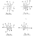
- Figure 1a shows a manual transmission according to the prior art in the "neutral or neutral position".
- a first switchable gear 2 and a second switchable gear 3 are rotatably mounted on a gear shaft 1.
- a "shift gear” 4 is arranged, which is rotatably connected to the gear shaft 1.
- a shift sleeve 5 is axially displaceably arranged on the shift gear 4 in a known manner. By axially shifting the shift sleeve 5, a rotationally fixed connection of the shift gear 4 or the gear shaft 1 with one of the two gear wheels 2 or 3 can be produced, which is shown in FIGS. 1b and 1c.
- Figures 2a-2d show different switching positions of a circuit arrangement according to the invention.
- the circuit arrangement has three “gearbox rotating bodies”, namely a first gearbox rotating body 8, a second gearbox rotating body 9 and a third gearbox rotating body 10 arranged between the first and second gearbox rotating bodies 8 and 9 respectively.
- the first gearbox rotating body 8 is a gearwheel that rotates with a first shaft 11 is connected.
- the gear wheel 8 has a gear toothing 8 ′ on its side facing the third gear rotating body 10.
- the second gear rotating body 9 is a gearwheel which is coupled to a gearwheel 13 via a hollow shaft 14 in a rotationally fixed manner.
- the third gear rotating body 10 is here a gear connected to a further shaft 15, the shaft 15 of the third gear rotating body 10 being guided through the hollow shaft 14 of the second gear rotating body 9.
- An axially displaceable shift sleeve 5 enables a "rotary coupling" of two of the gear rotating bodies 8-10 in each case.
- the shift sleeve 5 is pushed completely onto the second gear rotating body 9, that is to say it does not engage in any of the other two gear rotating bodies 8 or 10 a.
- the gear rotating bodies 8-10 can thus be rotated independently of one another.
- Figure 2b shows a "first engagement position" in which the shift sleeve 5 is shifted to the "left” compared to the idle position.
- the third gear rotating body 10 or the shaft 15 are connected in a rotationally fixed manner to the second gear rotating body 9 or the hollow shaft 14 and the gear 13 via the shift sleeve 5.
- FIG. 2c shows a second engagement position of the shift sleeve 5.
- the first gear rotating body 8 and the second gear rotating body 9 are connected to one another in a rotationally fixed manner via the gearshift sleeve 5.
- torque transmission from the first shaft 11 to the hollow shaft 14 is possible.
- the third gear rotating body 10 is "bridged" by the shift sleeve 5 in this shift position.
- FIG. 2d shows a third engagement position in which the first gear rotating body 8 and the third gear rotating body 10 are connected to one another in a rotationally fixed manner via the shift sleeve 5.
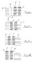
- FIGS. 3a-3d show the positions of the gear teeth in a "developed view" in accordance with the switching states of FIGS. 2a-2d.
- the gearshift sleeve 5 In the neutral position shown in FIG. 3a, the gearshift sleeve 5 is pushed completely onto the second gear rotating body 9, that is to say both partial gear teeth 5 ', 5 "of the gearshift sleeve 5 engage in an associated gear teeth 9' of the second gear rotating body 9.
- the gearshift sleeve 5 is here not with the gear teeth 8 'of the first Gear rotating body 8 and also not connected to the switching teeth 10 'of the third gear rotating body 10.
- a “connecting element” or a shift sleeve can be provided which has more than four switching positions.
- several neutral positions can be provided, or more than three gear rotating bodies can be provided, which can be shifted via a single shift sleeve.
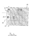
- Figure 4 shows a six-speed transmission with a reverse gear (6 + R transmission), which is schematically designated 16 here.
- the circuit arrangement described in FIGS. 2a-2d and 3a-3d is arranged here at the input of the transmission 16 and is designated by the letter A.
- the first gear rotating body 8 meshes with a gear 17 which is rotatably arranged on a shaft 18 of the gear 16.
- a gear wheel 19 is connected in a rotationally fixed manner to the shaft 18. By moving a shift sleeve 20, a rotationally fixed connection of the gear 17 to the gear 19 can be achieved.
- A, B, C, D and E here generally designate “connecting elements” or shift sleeves of the overall transmission, which can assume different shift positions, which will be explained in more detail below.
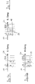
- Figures 5a - 5d show different switching states, namely the "gear positions 1 to 4".
- the shift sleeve 5 of the "connecting element A" is in each case in the neutral position (cf. FIG. 2a).
- the connecting element D is switched “to the left”, that is to say the torque is transmitted from the shaft 18 to the output shaft 21 via a gear stage 22.
- the connecting element A is in its "left" switching position, in which a direct torque transmission from the shaft 11 to the output shaft 21 connected to the third gear rotating body 10 takes place (cf. FIG. 2d).
- FIG. 5g shows the shift position of a reverse gear in which the torque is transmitted from the input shaft 11 via a gear stage 25 to the output shaft 21.
- the shift sleeve 5 is in its neutral position according to FIG. 2a.
- the connecting element B is in its left engagement position, in which the gear 17 is connected to the shaft 18 in a rotationally fixed manner.
Landscapes
- Engineering & Computer Science (AREA)
- General Engineering & Computer Science (AREA)
- Mechanical Engineering (AREA)
- Structure Of Transmissions (AREA)
- Control Of Transmission Device (AREA)
Applications Claiming Priority (2)
| Application Number | Priority Date | Filing Date | Title |
|---|---|---|---|
| DE2001134994 DE10134994A1 (de) | 2001-07-18 | 2001-07-18 | Schaltgetriebe |
| DE10134994 | 2001-07-18 |
Publications (2)
| Publication Number | Publication Date |
|---|---|
| EP1279862A2 true EP1279862A2 (fr) | 2003-01-29 |
| EP1279862A3 EP1279862A3 (fr) | 2008-12-17 |
Family
ID=7692252
Family Applications (1)
| Application Number | Title | Priority Date | Filing Date |
|---|---|---|---|
| EP02014388A Withdrawn EP1279862A3 (fr) | 2001-07-18 | 2002-06-28 | Boîte de vitesses |
Country Status (2)
| Country | Link |
|---|---|
| EP (1) | EP1279862A3 (fr) |
| DE (1) | DE10134994A1 (fr) |
Cited By (3)
| Publication number | Priority date | Publication date | Assignee | Title |
|---|---|---|---|---|
| WO2006117099A1 (fr) | 2005-05-03 | 2006-11-09 | Daimlerchrysler Ag | Boite de vitesses pourvue d'un arbre intermediaire pouvant etre decouple en prise directe |
| WO2006119829A1 (fr) * | 2005-05-11 | 2006-11-16 | Bayerische Motoren Werke | Boite de vitesses pour vehicule comprenant six vitesses avant pour un fonctionnement normal, une vitesse tout terrain ou une vitesse speciale cotes, ainsi qu'une vitesse arriere |
| CN107725693A (zh) * | 2017-11-15 | 2018-02-23 | 张家港川梭车业有限公司 | 一种两挡变速传动装置 |
Families Citing this family (2)
| Publication number | Priority date | Publication date | Assignee | Title |
|---|---|---|---|---|
| DE102012015006A1 (de) * | 2012-07-28 | 2014-01-30 | GM Global Technology Operations LLC (n. d. Gesetzen des Staates Delaware) | Kuppelvorrichtung mit einer Schaltmuffe fürein Schaltgetriebe |
| DE102014201251A1 (de) | 2014-01-23 | 2015-08-06 | Volkswagen Aktiengesellschaft | Schaltvorrichtung |
Family Cites Families (6)
| Publication number | Priority date | Publication date | Assignee | Title |
|---|---|---|---|---|
| DE1450746A1 (de) * | 1964-11-23 | 1969-03-20 | Hurth Masch Zahnrad Carl | Formschluessige Schaltung fuer Zweigang-Verteilergetriebe |
| DE3152696C2 (de) * | 1981-08-06 | 1985-10-03 | Zahnradfabrik Friedrichshafen Ag, 7990 Friedrichshafen | Stirnradwechselgetriebe |
| AT384090B (de) * | 1982-09-23 | 1987-09-25 | Steyr Daimler Puch Ag | Wenigstens zweigaengiges wechselgetriebe |
| JPS60154628U (ja) * | 1984-03-23 | 1985-10-15 | 株式会社 大金製作所 | 産業機械用車輌等の動力切換装置 |
| DE3939274A1 (de) * | 1989-11-28 | 1991-05-29 | Getrag Getriebe Zahnrad | Synchronisiereinrichtung fuer ein schaltgetriebe |
| DE19949230B4 (de) * | 1999-10-13 | 2010-04-29 | Zf Friedrichshafen Ag | 12-Gang-Getriebe |
-
2001
- 2001-07-18 DE DE2001134994 patent/DE10134994A1/de not_active Withdrawn
-
2002
- 2002-06-28 EP EP02014388A patent/EP1279862A3/fr not_active Withdrawn
Cited By (5)
| Publication number | Priority date | Publication date | Assignee | Title |
|---|---|---|---|---|
| WO2006117099A1 (fr) | 2005-05-03 | 2006-11-09 | Daimlerchrysler Ag | Boite de vitesses pourvue d'un arbre intermediaire pouvant etre decouple en prise directe |
| US7798937B2 (en) | 2005-05-03 | 2010-09-21 | Daimler Ag | Transmission with a countershaft which can be idled in direct gear |
| WO2006119829A1 (fr) * | 2005-05-11 | 2006-11-16 | Bayerische Motoren Werke | Boite de vitesses pour vehicule comprenant six vitesses avant pour un fonctionnement normal, une vitesse tout terrain ou une vitesse speciale cotes, ainsi qu'une vitesse arriere |
| US7430935B2 (en) | 2005-05-11 | 2008-10-07 | Bayerische Motoren Werke Aktiengesellschaft | Motor vehicle gearbox with six forward gears for normal driving, and with a crawling gear or hill gear and a reverse gear |
| CN107725693A (zh) * | 2017-11-15 | 2018-02-23 | 张家港川梭车业有限公司 | 一种两挡变速传动装置 |
Also Published As
| Publication number | Publication date |
|---|---|
| DE10134994A1 (de) | 2003-02-06 |
| EP1279862A3 (fr) | 2008-12-17 |
Similar Documents
| Publication | Publication Date | Title |
|---|---|---|
| DE4205668C2 (de) | Gangschaltgetriebe eines Kraftfahrzeugs | |
| EP1097315A2 (fr) | Systeme de boite de vitesses | |
| EP0557707A1 (fr) | Procédé de commander une boîte de vitesse pour une voiture | |
| EP1846669A1 (fr) | Transmission a double embrayage | |
| DE10316163A1 (de) | Mehrstufiges Schaltgetriebe für eine Brennkraftmaschine | |
| EP0248899B1 (fr) | Boite de changement a echelonnement multiple de vitesses | |
| EP2162635A2 (fr) | Boîte de vitesses à engrenages | |
| DE69707589T2 (de) | Kompaktes Handschaltgetriebe für Kraftfahrzeuge | |
| EP3259496B1 (fr) | Boîte de vitesses à double embrayage pour véhicule à moteur | |
| EP0713033A1 (fr) | Boîte de vitesses à arbre intermédiaire et avec réducteur planétaire pour véhicule | |
| EP3211269A1 (fr) | Boîte de vitesses à double embrayage pour véhicules automobiles | |
| AT503476B1 (de) | Getriebe für ein fahrzeug | |
| DE102010052746B4 (de) | Kompaktes Schaltgetriebe | |
| DE10134994A1 (de) | Schaltgetriebe | |
| DE102012015006A1 (de) | Kuppelvorrichtung mit einer Schaltmuffe fürein Schaltgetriebe | |
| DE102020005168B3 (de) | Doppelkupplungsgetriebe | |
| EP2864661B1 (fr) | Unité comprenant une boîte de vitesses et des embrayages et procédé de contrôle pour un agencement de transmission la comprenant | |
| DE102011105065A1 (de) | Zweiwellenschaltgetriebe für ein Kraftfahrzeug | |
| EP1000267B1 (fr) | Embrayage | |
| DE102004007815B4 (de) | Schaltgetriebe mit Sperrsynchronisation | |
| DE102023200195B4 (de) | Lastschaltbares Getriebe für ein in Gruppenbauweise ausgeführtes Kraftfahrzeuggetriebe, Kraftfahrzeuggetriebe und landwirtschaftliches oder kommunales Nutzfahrzeug | |
| AT524034B1 (de) | Antriebsstrang für ein kraftfahrzeug | |
| WO2014102038A1 (fr) | Boîte de vitesses commandée en charge | |
| DE10141275A1 (de) | Getriebeschaltvorrichtung |
Legal Events
| Date | Code | Title | Description |
|---|---|---|---|
| PUAI | Public reference made under article 153(3) epc to a published international application that has entered the european phase |
Free format text: ORIGINAL CODE: 0009012 |
|
| AK | Designated contracting states |
Designated state(s): AT BE CH CY DE DK ES FI FR GB GR IE IT LI LU MC NL PT SE TR |
|
| AX | Request for extension of the european patent |
Extension state: AL LT LV MK RO SI |
|
| PUAL | Search report despatched |
Free format text: ORIGINAL CODE: 0009013 |
|
| AK | Designated contracting states |
Kind code of ref document: A3 Designated state(s): AT BE CH CY DE DK ES FI FR GB GR IE IT LI LU MC NL PT SE TR |
|
| AX | Request for extension of the european patent |
Extension state: AL LT LV MK RO SI |
|
| STAA | Information on the status of an ep patent application or granted ep patent |
Free format text: STATUS: THE APPLICATION IS DEEMED TO BE WITHDRAWN |
|
| 18D | Application deemed to be withdrawn |
Effective date: 20090103 |