EP1280175B1 - Relais - Google Patents
Relais Download PDFInfo
- Publication number
- EP1280175B1 EP1280175B1 EP02254418A EP02254418A EP1280175B1 EP 1280175 B1 EP1280175 B1 EP 1280175B1 EP 02254418 A EP02254418 A EP 02254418A EP 02254418 A EP02254418 A EP 02254418A EP 1280175 B1 EP1280175 B1 EP 1280175B1
- Authority
- EP
- European Patent Office
- Prior art keywords
- contact
- armature
- moveable
- fixed contact
- support
- Prior art date
- Legal status (The legal status is an assumption and is not a legal conclusion. Google has not performed a legal analysis and makes no representation as to the accuracy of the status listed.)
- Expired - Lifetime
Links
- 230000000284 resting effect Effects 0.000 claims description 6
- 238000013459 approach Methods 0.000 description 1
Images


Classifications
-
- H—ELECTRICITY
- H01—ELECTRIC ELEMENTS
- H01H—ELECTRIC SWITCHES; RELAYS; SELECTORS; EMERGENCY PROTECTIVE DEVICES
- H01H50/00—Details of electromagnetic relays
- H01H50/54—Contact arrangements
- H01H50/60—Contact arrangements moving contact being rigidly combined with movable part of magnetic circuit
Definitions
- the invention relates to an electromagnetic relay. More particularly, the invention relates to an electromagnetic relay suitable for switching loads at DC voltages exceeding 24V for use in applications such as an automobile.
- Examples of conventional electromagnetic relays are disclosed in United States Patent Nos. 5,864,270 and 6,140,895 . These relays are manufactured to switch loads at voltages below 24V. Because many applications require a greater load range, typically exceeding 15A, these relays can not adequately accommodate applications where higher currents are required. In addition, conventional relays typically have a single set of opening contacts.or a single set of closing contacts. A single set of opening or closing contacts is not sufficient for many applications.
- an electromagnetic relay having more than one set of opening and/or closing contacts and being suitable for switching DC voltages exceeding 24V and currents exceeding 15A. It is also desirable that the relay be both compact and economical.
- a prior art relay is disclosed in United States Patent No. 4,509,028 .
- the relay includes a frame supporting a pair of fixed contacts and a core surrounded by a coil.
- a pair of moveable contacts are provided on a movable contact bridge which is connected to an armature by a torsional spring.
- the armature is biased towards a rest position in which the moveable contacts do not engage the fixed contacts.
- Actuation of the relay causes movement of the armature to bring the moveable contacts into engagement with the fixed contacts.
- DE-A-32 32 679 discloses a further relay according to the preamble of claim 1.
- an electromagnetic relay comprising a coil, a base, a yoke, a core, and an armature, the armature is mechanically coupled to a moveable contact bridge, which has a first moveable contact and a second moveable contact, by a transfer spring and has an armature spring for urging the armature towards a resting position; a torsion bar attached to the transfer spring that extends substantially transversely to the contact bridge, characterised by the torsion bar having a frame having a support rod extending therethrough and a contact bridge support member mounted on the support rod for attachment to the contact bridge.
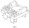
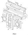
- electromagnetic relay 100 has a base 20, a coil 1, a yoke 2 and a core 3.
- the base 20 has fixed contact supports 9a, 9b, 10a, 10b.
- the fixed contact supports 9a, 9b, 10a, 10b extend through the base 20 to connection pins for electrically connecting the relay 100 to circuitry (not shown).
- Each fixed contact support 9a, 9b, 10a, 10b is provided with a fixed contact 13a, 13b, 14a, 14b, respectively.
- the yoke 2 has a yoke pole surface 5 positioned adjacent to an armature 4.
- the armature 4 has an armature pole surface 6 and an armature spring 19.
- the armature spring 19 is positioned at a first end of the armature 4 and is preferably made from a flexible material having a relatively low stiffness so to allow movement of the armature 4 with little mechanical resistance.
- the armature pole surface 6 is positioned at a second end of the armature 4 and has a transfer spring 7.
- the transfer spring 7 preferably has a torsion bar 7' extending substantially transversely to the direction of movement to increase the stiffness of the transfer spring 7.
- a relatively stiff frame 16 extends at essentially a right angle from the torsion bar 7'.
- a support rod 17 extends through a middle of the frame 16.
- a support member 18 is fixed to the support rod 17.
- the support rod 17 has a substantially smaller width than members of the frame 16 enabling the support rod 17 to be relatively flexible.
- the support member 18 is attached to a moveable contact bridge 8.
- Moveable contact supports 11a, 11b are mounted on a front of the contact bridge 8.
- Moveable contacts 12a, 12b are mounted on the moveable contact supports 11a, 11b.
- Moveable back contact supports are mounted on a back of the contact bridge 8 and moveable back contacts are mounted on the moveable back contact supports in a position mirroring the moveable contact supports 11a, 11b and the moveable contacts 12a, 12b.
- the support member 18 provides desirable resilience in the direction of movement while maintaining a desirable degree of stiffness transversely to the direction of movement, allowing an advantageous transfer of available force onto the contact bridge 8.
- the torsion bar 7' allows torsion of the support rod 17 and hence some rotation of the contact bridge 8 relative to the frame 16 and the transfer spring 7.
- the rotation of the contact bridge 8 and the transfer spring 7, however small, allows the moveable contacts 12a, 12b to move between the fixed contacts 13a, 13b, 14a, 14b.
- the armature spring 19 urges the armature 4 into a resting position.
- the transfer spring 7 transfers the spring force onto the contact bridge 8 to cause the moveable contacts 12a, 12b to contact the fixed contacts 13a, 13b.
- the armature 4 is moved from the resting position and pivots so that the armature pole surface 6 tangentially approaches the yoke pole surface 5.
- the transfer spring 7 transfers the armature 4 movement onto the contact bridge 8, which then moves away from the fixed contacts 13a, 13b.
- the opposite set of fixed contacts 14a, 14b is contacted before the armature 4 reaches a final position.
Landscapes
- Physics & Mathematics (AREA)
- Electromagnetism (AREA)
- Contacts (AREA)
- Relay Circuits (AREA)
Claims (3)
- Elektromagnetisches Relais (100), das Folgendes umfasst: eine Spule (1), eine Basis (20), ein Joch (2), einen Kern (3) und einen Anker (4), wobei der Anker (4) durch eine Übertragungsfeder (7) mechanisch an eine bewegliche Kontaktbrücke (8), die einen ersten beweglichen Kontakt (12a) und einen zweiten beweglichen Kontakt (12b) hat, gekoppelt ist und eine Ankerfeder (19) hat, um den Anker (4) zu einer Ruheposition hin zu drängen,
einen an der Übertragungsfeder (7) befestigten Torsionsstab (7'), der sich im Wesentlichen quer zu der Kontaktbrücke (8) erstreckt, dadurch gekennzeichnet, dass der Torsionsstab (7') einen Rahmen (16) hat, der einen Stützstab (17), der sich durch denselben erstreckt, und ein Kontaktbrückenstützelement (18), das für eine Befestigung an der Kontaktbrücke (8) an dem Stützstab (17) angebracht ist, hat. - Elektromagnetisches Relais (100) nach Anspruch 1, dadurch gekennzeichnet, dass die beweglichen Kontakte (12a, 12b) an beweglichen Kontaktstützen (11a, 11b) befestigt sind.
- Elektromagnetisches Relais (100) nach Anspruch 1 oder 2, dadurch gekennzeichnet, dass die Basis (20) eine erste unbewegliche Kontaktstütze (9a, 9b) mit einem ersten unbeweglichen Kontakt (13a, 13b) und eine zweite unbewegliche Kontaktstütze (10a, 10b) mit einem zweiten unbeweglichen Kontakt (14a, 14b) hat, wobei die Kontaktbrücke (8) zwischen der ersten unbeweglichen Kontaktstütze (9a, 9b) und der zweiten unbeweglichen Kontaktstütze (10a, 10b) angeordnet ist derart, dass sich der erste unbewegliche Kontakt (13a, 13b) im Wesentlichen angrenzend an den ersten beweglichen Kontakt (12a, 12b) befindet und sich der zweite unbewegliche Kontakt (14a, 14b) im Wesentlichen angrenzend an den zweiten beweglichen Kontakt befindet.
Applications Claiming Priority (2)
| Application Number | Priority Date | Filing Date | Title |
|---|---|---|---|
| GBGB0118327.6A GB0118327D0 (en) | 2001-07-27 | 2001-07-27 | Relay |
| GB0118327 | 2001-07-27 |
Publications (3)
| Publication Number | Publication Date |
|---|---|
| EP1280175A2 EP1280175A2 (de) | 2003-01-29 |
| EP1280175A3 EP1280175A3 (de) | 2004-10-13 |
| EP1280175B1 true EP1280175B1 (de) | 2009-10-28 |
Family
ID=9919299
Family Applications (1)
| Application Number | Title | Priority Date | Filing Date |
|---|---|---|---|
| EP02254418A Expired - Lifetime EP1280175B1 (de) | 2001-07-27 | 2002-06-25 | Relais |
Country Status (5)
| Country | Link |
|---|---|
| US (1) | US6611184B2 (de) |
| EP (1) | EP1280175B1 (de) |
| JP (1) | JP2003077383A (de) |
| DE (1) | DE60234147D1 (de) |
| GB (1) | GB0118327D0 (de) |
Families Citing this family (7)
| Publication number | Priority date | Publication date | Assignee | Title |
|---|---|---|---|---|
| JP3989928B2 (ja) * | 2004-11-02 | 2007-10-10 | ウチヤ・サーモスタット株式会社 | 電磁リレー |
| JP4116022B2 (ja) * | 2005-07-11 | 2008-07-09 | ウチヤ・サーモスタット株式会社 | 電磁リレー |
| US7548146B2 (en) * | 2006-12-27 | 2009-06-16 | Tyco Electronics Corporation | Power relay |
| DE202007007355U1 (de) * | 2007-05-22 | 2007-09-06 | Takata-Petri Ag | Gasstromverteiler für ein Gassackmodul |
| JP5222669B2 (ja) * | 2008-09-16 | 2013-06-26 | 富士通コンポーネント株式会社 | 電磁継電器 |
| TW201029037A (en) * | 2009-01-21 | 2010-08-01 | Good Sky Electric Co Ltd | Electromagnetic relay and assembling method of its electromagnet unit |
| CN112420452B (zh) * | 2020-11-16 | 2023-11-14 | 天翼物联科技有限公司 | 一种切换型电磁继电器及其控制电路 |
Family Cites Families (6)
| Publication number | Priority date | Publication date | Assignee | Title |
|---|---|---|---|---|
| DE3232679C2 (de) * | 1981-09-04 | 1985-06-05 | Siemens AG, 1000 Berlin und 8000 München | Elektromagnetisches Schaltrelais für hohe Strombelastung |
| DE8234360U1 (de) | 1982-12-07 | 1983-06-09 | Siemens AG, 1000 Berlin und 8000 München | Elektromagnetisches Relais |
| DE8235283U1 (de) * | 1982-12-15 | 1983-06-09 | Siemens AG, 1000 Berlin und 8000 München | Elektromagnetisches Relais |
| ATE170663T1 (de) | 1995-03-21 | 1998-09-15 | Siemens Ag | Elektromagnetisches relais |
| DE19522931A1 (de) * | 1995-06-23 | 1997-01-02 | Siemens Ag | Relais für hohe Schaltleistungen |
| DE19727863C1 (de) | 1997-06-30 | 1999-01-21 | Siemens Ag | Elektromagnetisches Relais |
-
2001
- 2001-07-27 GB GBGB0118327.6A patent/GB0118327D0/en not_active Ceased
-
2002
- 2002-06-25 DE DE60234147T patent/DE60234147D1/de not_active Expired - Lifetime
- 2002-06-25 EP EP02254418A patent/EP1280175B1/de not_active Expired - Lifetime
- 2002-07-12 JP JP2002203367A patent/JP2003077383A/ja not_active Withdrawn
- 2002-07-24 US US10/202,582 patent/US6611184B2/en not_active Expired - Fee Related
Also Published As
| Publication number | Publication date |
|---|---|
| US6611184B2 (en) | 2003-08-26 |
| JP2003077383A (ja) | 2003-03-14 |
| EP1280175A3 (de) | 2004-10-13 |
| EP1280175A2 (de) | 2003-01-29 |
| GB0118327D0 (en) | 2001-09-19 |
| US20030030520A1 (en) | 2003-02-13 |
| DE60234147D1 (de) | 2009-12-10 |
Similar Documents
| Publication | Publication Date | Title |
|---|---|---|
| CN1092392C (zh) | 电磁开关装置 | |
| JP4629754B2 (ja) | 低電圧サーキット・ブレーカ | |
| EP0347999A2 (de) | Elektrische Schalteinrichtung, bei der die axiale Betätigungskraft nur einen kleinen Teil der Kontaktkraft ausmacht | |
| JP5618396B2 (ja) | リレー | |
| EP1280175B1 (de) | Relais | |
| US7098762B2 (en) | Electromechanical switch | |
| JP2663983B2 (ja) | 継電器のための接触装置 | |
| US5498846A (en) | Toggle switches | |
| US6084488A (en) | Compact high current relay | |
| US6664885B2 (en) | Thermally activated latch | |
| JP4184001B2 (ja) | 切換継電器 | |
| EP0534572B1 (de) | Elektrisches bistabiles Relais | |
| JP4173006B2 (ja) | 開閉接触子装置 | |
| US7939992B2 (en) | Electrical switch element, particularly a relay, with swivelling lever switch mechanism | |
| US5038124A (en) | Electromagnetic switchgear | |
| CN1319099C (zh) | 元件数量减少的低压自动电路断路器 | |
| CN2530346Y (zh) | 热过载继电器内的释放杆 | |
| US6677841B2 (en) | System and method for mounting a pusher and moveable contact in a contact block | |
| JP3228105B2 (ja) | 電気接点 | |
| JPS6340228A (ja) | 回路しや断器 | |
| CN220914122U (zh) | 一种继电器及车辆 | |
| US5268544A (en) | Vacuum relay with a contact unit located in a vacuum | |
| CN121662626A (zh) | 具有预充电继电器的多开关接触器组件 | |
| JPS645732B2 (de) | ||
| JPH0241787Y2 (de) |
Legal Events
| Date | Code | Title | Description |
|---|---|---|---|
| PUAI | Public reference made under article 153(3) epc to a published international application that has entered the european phase |
Free format text: ORIGINAL CODE: 0009012 |
|
| AK | Designated contracting states |
Designated state(s): AT BE CH CY DE DK ES FI FR GB GR IE IT LI LU MC NL PT SE TR |
|
| AX | Request for extension of the european patent |
Extension state: AL LT LV MK RO SI |
|
| PUAL | Search report despatched |
Free format text: ORIGINAL CODE: 0009013 |
|
| AK | Designated contracting states |
Kind code of ref document: A3 Designated state(s): AT BE CH CY DE DK ES FI FR GB GR IE IT LI LU MC NL PT SE TR |
|
| AX | Request for extension of the european patent |
Extension state: AL LT LV MK RO SI |
|
| 17P | Request for examination filed |
Effective date: 20041119 |
|
| AKX | Designation fees paid |
Designated state(s): DE FR GB IT |
|
| 17Q | First examination report despatched |
Effective date: 20080310 |
|
| GRAP | Despatch of communication of intention to grant a patent |
Free format text: ORIGINAL CODE: EPIDOSNIGR1 |
|
| GRAS | Grant fee paid |
Free format text: ORIGINAL CODE: EPIDOSNIGR3 |
|
| GRAA | (expected) grant |
Free format text: ORIGINAL CODE: 0009210 |
|
| AK | Designated contracting states |
Kind code of ref document: B1 Designated state(s): DE FR GB IT |
|
| REG | Reference to a national code |
Ref country code: GB Ref legal event code: FG4D |
|
| REF | Corresponds to: |
Ref document number: 60234147 Country of ref document: DE Date of ref document: 20091210 Kind code of ref document: P |
|
| PLBE | No opposition filed within time limit |
Free format text: ORIGINAL CODE: 0009261 |
|
| STAA | Information on the status of an ep patent application or granted ep patent |
Free format text: STATUS: NO OPPOSITION FILED WITHIN TIME LIMIT |
|
| 26N | No opposition filed |
Effective date: 20100729 |
|
| PG25 | Lapsed in a contracting state [announced via postgrant information from national office to epo] |
Ref country code: IT Free format text: LAPSE BECAUSE OF FAILURE TO SUBMIT A TRANSLATION OF THE DESCRIPTION OR TO PAY THE FEE WITHIN THE PRESCRIBED TIME-LIMIT Effective date: 20091028 |
|
| REG | Reference to a national code |
Ref country code: FR Ref legal event code: PLFP Year of fee payment: 14 |
|
| REG | Reference to a national code |
Ref country code: DE Ref legal event code: R082 Ref document number: 60234147 Country of ref document: DE Representative=s name: MARKS & CLERK (LUXEMBOURG) LLP, LU Ref country code: DE Ref legal event code: R081 Ref document number: 60234147 Country of ref document: DE Owner name: TE CONNECTIVITY GERMANY GMBH, DE Free format text: FORMER OWNER: TYCO ELECTRONICS AMP GMBH, 64625 BENSHEIM, DE |
|
| REG | Reference to a national code |
Ref country code: FR Ref legal event code: CD Owner name: TE CONNECTIVITY GERMANY GMBH Effective date: 20151027 |
|
| REG | Reference to a national code |
Ref country code: FR Ref legal event code: PLFP Year of fee payment: 15 |
|
| REG | Reference to a national code |
Ref country code: FR Ref legal event code: PLFP Year of fee payment: 16 |
|
| REG | Reference to a national code |
Ref country code: FR Ref legal event code: PLFP Year of fee payment: 17 |
|
| PGFP | Annual fee paid to national office [announced via postgrant information from national office to epo] |
Ref country code: DE Payment date: 20210602 Year of fee payment: 20 Ref country code: FR Payment date: 20210514 Year of fee payment: 20 |
|
| PGFP | Annual fee paid to national office [announced via postgrant information from national office to epo] |
Ref country code: GB Payment date: 20210603 Year of fee payment: 20 |
|
| REG | Reference to a national code |
Ref country code: DE Ref legal event code: R071 Ref document number: 60234147 Country of ref document: DE |
|
| REG | Reference to a national code |
Ref country code: GB Ref legal event code: PE20 Expiry date: 20220624 |
|
| PG25 | Lapsed in a contracting state [announced via postgrant information from national office to epo] |
Ref country code: GB Free format text: LAPSE BECAUSE OF EXPIRATION OF PROTECTION Effective date: 20220624 |