EP1280268A2 - Dispositif de détection d'état de rotation d'un moteur à réluctance - Google Patents
Dispositif de détection d'état de rotation d'un moteur à réluctance Download PDFInfo
- Publication number
- EP1280268A2 EP1280268A2 EP02014682A EP02014682A EP1280268A2 EP 1280268 A2 EP1280268 A2 EP 1280268A2 EP 02014682 A EP02014682 A EP 02014682A EP 02014682 A EP02014682 A EP 02014682A EP 1280268 A2 EP1280268 A2 EP 1280268A2
- Authority
- EP
- European Patent Office
- Prior art keywords
- rotor
- sensor
- detection device
- state detection
- encoder
- Prior art date
- Legal status (The legal status is an assumption and is not a legal conclusion. Google has not performed a legal analysis and makes no representation as to the accuracy of the status listed.)
- Granted
Links
Images



Classifications
-
- H—ELECTRICITY
- H02—GENERATION; CONVERSION OR DISTRIBUTION OF ELECTRIC POWER
- H02K—DYNAMO-ELECTRIC MACHINES
- H02K29/00—Motors or generators having non-mechanical commutating devices, e.g. discharge tubes or semiconductor devices
- H02K29/06—Motors or generators having non-mechanical commutating devices, e.g. discharge tubes or semiconductor devices with position sensing devices
- H02K29/10—Motors or generators having non-mechanical commutating devices, e.g. discharge tubes or semiconductor devices with position sensing devices using light effect devices
-
- H—ELECTRICITY
- H02—GENERATION; CONVERSION OR DISTRIBUTION OF ELECTRIC POWER
- H02K—DYNAMO-ELECTRIC MACHINES
- H02K19/00—Synchronous motors or generators
- H02K19/02—Synchronous motors
- H02K19/10—Synchronous motors for multi-phase current
- H02K19/103—Motors having windings on the stator and a variable reluctance soft-iron rotor without windings
Definitions
- the invention relates to a rotational state detection device for a reluctance motor, the reluctance motor having a plurality of rotor segments, in particular four rotor segments, and a number of coils dependent thereon, namely four coils in the case of four rotor segments.
- stator currents and thus the stator field must be controlled depending on the rotor position.
- the holding disk of the rotor plates is shaped in a cylindrical manner on the largest possible outer radius, on which cylinder, for example, suitable circle segments have been removed.
- a carrier for electronic components is provided above the sensor disc is arranged.
- This carrier — printed circuit board preferably extends parallel to the alignment of the rotor plates, and therefore perpendicular to the rotor axis.
- This circuit board is preferably a carrier for electronic components, for example for detecting the position of the rotor.
- the carrier is arranged stationary and can also be used to contact the coils. Connections of the coils can thus protrude beyond them, so that they can be immersed in the circuit board or in the carrier.
- the circuit board has a circular disk-shaped plan with a connection section projecting outward beyond the stator core, the diameter of the circular disk-shaped plan being adapted to the inside diameter of the stator core.
- a board edge connector can be arranged, via which the coil pairs can be clearly identified.
- the entire electronics or at least parts thereof can be integrated on the printed circuit board or the carrier. At the same time, this offers the advantage of a very short conductor path, so that EMC interference is avoided or at least reduced.
- the printed circuit board has a conversion electronics for driving the motor to the left and to the right. Furthermore, it is preferred to place the evaluation electronics on the carrier for detecting the rotor position and the stator current control.
- the electronic components are arranged on the underside of the carrier, facing the sensor disc. For example, in the case of an exemplary hollow cylindrical configuration of the encoder disk, it is conceivable to nest it with the electronic components. This also results in additional cooling of the electronic components by the rotating ones Encoder disk.
- An additional advantage is achieved in that sensors are arranged on the underside of the carrier, which interact with the sensor disc.
- a sensor segment assigned to the rotor segment is formed which can be detected by a fixed sensor.
- the encoder disc can be hollow-cylindrical in shape, the encoder configurations being formed by window-like free cuts in the axially aligned cylinder wall of the encoder disc.
- Each encoder shape is clearly assigned to a rotor segment. For example, it can be provided that two sensor configurations are assigned to each rotor segment.
- stator poles and four rotor poles are provided with a total of eight sensor configurations, two sensor configurations each forming a pair of configurations that can be assigned to a rotor segment.
- an encoder shape is assigned to each rotor segment.
- an encoder disk with six encoder configurations is also provided.
- two transmitter forms each have a certain distance between them.
- a certain distance is provided between two sensor designs of circumferentially adjacent pairs of sensor designs. This distance is preferably chosen to be greater than the distance between two transmitter forms of a pair.
- a simple determination of the rotor position is achieved in that at least two sensors are provided that are circumferentially offset with respect to the sensor configurations.
- the circumferential offset dimension of the sensors to one another is adapted to the distance between the rotor segments.
- the circumferential distance between the sensors differ from the distance and, if appropriate, from the distance between two circumferentially adjacent sensor designs or pairs of sensor designs.
- the circumferential distance between the sensors is chosen to be smaller than the distance between the encoder shapes.
- at least four sensors are provided, two of which each interact as a sensor barrier.
- one transmitter or receiver is arranged radially on the outside and one receiver or transmitter is arranged radially on the inside of the transmitter forms.
- the encoder shapes of the encoder disk pass through the sensor barriers when the rotor rotates, which results in a detection scheme which can distinguish three different positions.
- the stator currents for motor optimization can be controlled in accordance with the detected position.
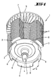
- a rotor 1 with a rotor axle body 2 and four rotor segments 3 arranged uniformly at an angle around the rotor axle body 2 is initially shown and described with reference to FIG. 1.
- the rotor 1 is formed here by individual rotor laminations 4, which are non-rotatably stacked on the rotor axle body 2 in the axial direction and which are between two holding disks 5, 6 are mounted. These holding disks 5, 6 perform a double function.
- the holding disc 5 is also designed as a cooling fan 7, with a diameter that corresponds approximately to the rotor diameter in the area of the rotor segments 3.
- the holding disk 6 opposite this cooling fan 7 is essentially hollow-cylindrical in shape, segments being cut free in the region of the cylinder wall facing away from the rotor plates 4, for the purpose of separating donor shapes 8 in the form of circular sections.
- the holding disk 6 accordingly also forms an encoder disk 9. The latter has a clearly defined assignment to the rotor position, due to the rotationally fixed arrangement of the encoder disk 9.
- each encoder form 8 includes approximately one An angle of 60 °, wherein a transmitter formation 8 - viewed in a plan - begins in the middle of a rotor segment 3 and ends at a distance in front of the next rotor segment 3 which is spaced apart.
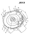
- the four-pole rotor 1 shown in FIG. 1 can be assigned to a stator 10 with six coils 11 arranged uniformly around the axis of rotation x of the rotor 1 (see FIG. 2).
- a fixed support 12 for the electronic components is arranged above the sensor disc 9 by connection to the stator 10.
- Conductor tracks are initially located on this carrier 12 13, via which the windings of the coils 11 are automatically and uniquely connected to one another.
- the carrier 12 has a substantially circular disk-shaped plan with a connection section 14 projecting outwards beyond the stator 10, the diameter of the circular disk-shaped plan being approximately matched to the inside diameter of the stator core.
- the coils 11 can be uniquely identified via a board edge connector.
- a sensor system on the carrier 12 which, in the case of a three-phase motor in the configuration shown, with six stator coils 11 and four rotor poles (rotor segments 3) consists of at least two sensors 15 arranged circumferentially offset with respect to the encoder forms 8.
- the sensors 15, which are not shown in the first exemplary embodiment according to FIGS. 1 and 2, are in a known angular relationship to the individual coils 11, so that the correct phase assignment of the sensor signals is clearly realized.
- the signals from the sensors are also on the edge of the carrier 12, i. H. placed in the area of the connection section 14, so that here, too, the connection to the electronics can be established with a board edge connector or the like.
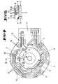
- FIG. 3 shows a second embodiment of a four-pole rotor 1 for a 4/6 reluctance motor. This differs from the exemplary embodiment described above in the configuration of the encoder disk 9.
- a pair of encoder formations 8, which are assigned to a rotor segment 3, are cut free from the cylinder wall of the encoder disc 9, each encoder configuration 8 of a pair 16 including an angle ⁇ of 15 ° with respect to the axis of rotation x and the distance a between the encoder configurations 8 of a pair 16 corresponds to the circumferential dimension b of an encoder formation 8.
- the opposite marginal edges of adjacent encoder shapes 8 of a pair 16 accordingly also form an angle ⁇ of 15 °.
- the assignment of the encoder formations 8 to the rotor segments 3 is clear. In this way, one encoder shape 8 of a pair 16 is positioned in the center of the assigned rotor segment 3. Depending on the direction of rotation of the rotor 1, the other encoder formation 8 of the pair 16 is arranged at an angle to the first transmitter formation 8 in front of or behind the rotor segment 3.
- the circumferential distance d between the sensors 15 and the sensor barriers 17 is different from the distance a between the sensor designs 8 and the distance c between two circumferentially adjacent sensor designs 8.
- a circumferential distance d between the sensor barriers 17 is selected which is greater than the distance a between two encoder shapes 8.
- the sensor barriers 17 are arranged here that they enclose an angle of approx. 45 ° with respect to the axis of rotation x.
- the sensor barriers 17 are arranged on the underside of the carrier 12 in such a way that the sensor formations 8 connected to the rotor 1 in a rotationally fixed manner pass through the sensor barriers 17.
- further electronic components 18, for example for evaluating the sensor signals and for actuating the coils 11 as a function of the sensor signals, also on the underside, can be arranged on the carrier 12 — printed circuit board — facing the sensor disc 9 his.
- these electronic components 18 can protrude into the interior space formed by the cylinder wall of the encoder disk 9, as a result of which the electronic components 18 do not adversely contribute to the height of the motor - axial extension of the motor.
- the electronic components 18 experience additional cooling in such an arrangement through the rotating encoder disk 9.
- the rotor position is clearly recognized in this exemplary embodiment. If, however, a value E of 0 is determined, the current rotor position is decided after the next value to be determined is determined.
- a direct juxtaposition of the rotor segment 3 and the coil 11 is achieved when the result value E is 3, i. H. when both sensor barriers 17 are simultaneously traversed by sensor formations 8 and provoke a corresponding signal.
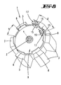
- the rotor 1 has six rotor segments 3 which are arranged at an angle around the axis of rotation x and which cooperate with eight coils 11 in the reluctance motor.
- the encoder disk 9 here has the same number of rotor segments 3, namely six encoder formations 8, each encoder form 8 being arranged circumferentially at the level of a rotor segment 3.
- the distance a between the encoder formations 8 corresponds approximately to the circumferential dimension b of each encoder form 8, so that the latter form an angle ⁇ of approximately 30 ° with respect to the axis of rotation x.
- sensors 15 in the form of two sensor barriers 17 are arranged on the underside of the carrier 12 for the electronic components 18, the circumferential distance d between them being larger than the distance a between the sensor shapes 8.
- a sensor shape angle ⁇ of 30 ° is used here
- Angle between the sensor barriers 17 of 45 ° is provided.
- the rotor position can be clearly detected in any position.
- the digital result value E is also between 0 and 3 here.
- the positioning of the sensors 15 or sensor barriers 17 relative to the coils 11 is essential for detecting the position of the rotor 1. This correct positioning is ensured in the simplest way by the carrier 12, which carries both the sensors 15 and the coils 11 contacting.
Landscapes
- Engineering & Computer Science (AREA)
- Power Engineering (AREA)
- Synchronous Machinery (AREA)
- Transmission And Conversion Of Sensor Element Output (AREA)
Applications Claiming Priority (2)
| Application Number | Priority Date | Filing Date | Title |
|---|---|---|---|
| DE10135689A DE10135689A1 (de) | 2000-07-21 | 2001-07-16 | Drehzustand-Erfassungseinrichtung für einen Reluktanzmotor |
| DE10135689 | 2001-07-16 |
Publications (3)
| Publication Number | Publication Date |
|---|---|
| EP1280268A2 true EP1280268A2 (fr) | 2003-01-29 |
| EP1280268A3 EP1280268A3 (fr) | 2005-07-27 |
| EP1280268B1 EP1280268B1 (fr) | 2020-11-11 |
Family
ID=7692707
Family Applications (1)
| Application Number | Title | Priority Date | Filing Date |
|---|---|---|---|
| EP02014682.5A Expired - Lifetime EP1280268B1 (fr) | 2001-07-16 | 2002-07-03 | Dispositif de détection optique de rotation pour un moteur à réluctance |
Country Status (2)
| Country | Link |
|---|---|
| EP (1) | EP1280268B1 (fr) |
| ES (1) | ES2834920T3 (fr) |
Citations (4)
| Publication number | Priority date | Publication date | Assignee | Title |
|---|---|---|---|---|
| US773829A (en) | 1903-07-27 | 1904-11-01 | August Uhri | Oil-cup. |
| EP0874442A2 (fr) | 1997-04-22 | 1998-10-28 | Emerson Electric Co. | Moteur électrique ayant un système de flux d'air de refroidissement amélioré |
| US5866962A (en) | 1996-11-30 | 1999-02-02 | Samsung Electronics Co., Ltd. | Rotor position detecting apparatus in switched reluctance motor |
| DE10035540A1 (de) | 2000-04-01 | 2001-10-04 | Vorwerk Co Interholding | Reluktanzmotor und Verfahren zur Regelung eines Reluktanzmotors |
Family Cites Families (4)
| Publication number | Priority date | Publication date | Assignee | Title |
|---|---|---|---|---|
| FR2603667B1 (fr) * | 1986-09-10 | 1990-09-28 | Etri Sa | Ventilateur centrifuge entraine par un moteur a courant continu et a commutation electronique |
| GB9311694D0 (en) * | 1993-06-07 | 1993-07-21 | Switched Reluctance Drives Ltd | Electric machine rotor prosition encoder |
| US5877568A (en) * | 1996-05-31 | 1999-03-02 | Emerson Electric Co. | Rotor position sensing system |
| JPH1066310A (ja) * | 1996-08-19 | 1998-03-06 | Secoh Giken Inc | 2個1組のコイルにより3相の位置検知信号を得る装置 |
-
2002
- 2002-07-03 EP EP02014682.5A patent/EP1280268B1/fr not_active Expired - Lifetime
- 2002-07-03 ES ES02014682T patent/ES2834920T3/es not_active Expired - Lifetime
Patent Citations (4)
| Publication number | Priority date | Publication date | Assignee | Title |
|---|---|---|---|---|
| US773829A (en) | 1903-07-27 | 1904-11-01 | August Uhri | Oil-cup. |
| US5866962A (en) | 1996-11-30 | 1999-02-02 | Samsung Electronics Co., Ltd. | Rotor position detecting apparatus in switched reluctance motor |
| EP0874442A2 (fr) | 1997-04-22 | 1998-10-28 | Emerson Electric Co. | Moteur électrique ayant un système de flux d'air de refroidissement amélioré |
| DE10035540A1 (de) | 2000-04-01 | 2001-10-04 | Vorwerk Co Interholding | Reluktanzmotor und Verfahren zur Regelung eines Reluktanzmotors |
Also Published As
| Publication number | Publication date |
|---|---|
| ES2834920T3 (es) | 2021-06-21 |
| EP1280268A3 (fr) | 2005-07-27 |
| EP1280268B1 (fr) | 2020-11-11 |
Similar Documents
| Publication | Publication Date | Title |
|---|---|---|
| EP1670121B2 (fr) | Machine électrique, moteur à courant continu sans balais en particulier | |
| DE69526770T2 (de) | Resolver für Reluktanzmotor für Lenkhilfe mit Ringen und sinusförmigen Leitern | |
| DE68921721T2 (de) | Elektronisch kommutierter Motor und dafür feststehender Anker mit Schlitzen aufweisenden Zähnen und mit einer Schräge zwischen den Nuten und dem permanenten Magnetfeld zum Abschwächen des pulsierenden Drehmoments. | |
| DE69908786T2 (de) | Bürstenlosen Motor mit Vorrichtung zur Ermittlung der Rotorstellung | |
| DE10033561B4 (de) | Elektronisch kommutierter Motor mit Kommutierungssignal | |
| EP0286905A1 (fr) | Moteur à courant continu à commutation électronique | |
| EP0554900B1 (fr) | Moteur électrique avec un capteur inductif de position | |
| DE102009036274A1 (de) | Drehungserfassungsvorrichtung und Gleichstrommotor | |
| EP1279218B1 (fr) | Procede de contrôle d'un moteur a reluctance | |
| DE4028551C2 (fr) | ||
| DE102005039881B4 (de) | Resolver | |
| DE4120023C1 (fr) | ||
| EP1397691A1 (fr) | Dispositif permettant de generer un signal dependant de la vitesse de rotation pour un moteur electrique, en particulier pour un moteur a courant continu a commutation electronique | |
| EP4242616B1 (fr) | Dispositif de capteur de couple, ensemble de conducteur de flux et conducteur de flux | |
| DE102011003762A1 (de) | Gleichstrommotorsteuervorrichtung und Verfahren zur Erfassung eines Zustands des Gleichstrommotors | |
| DE19521557C2 (de) | Bürstenloser Elektromotor insbesondere für das Gebläse einer Klimaanlage eines Kraftfahrzeugs | |
| DE102017101041A1 (de) | Motor und Resolver davon | |
| DE2423665C3 (de) | Kommutatorloser Gleichstrommotor mit axialem Luftspalt | |
| EP1280268B1 (fr) | Dispositif de détection optique de rotation pour un moteur à réluctance | |
| DE10135689A1 (de) | Drehzustand-Erfassungseinrichtung für einen Reluktanzmotor | |
| DE2934183C2 (fr) | ||
| EP1866606B1 (fr) | Systeme de detection de position | |
| DE102017222402B4 (de) | Drehwinkelmesseinrichtung | |
| EP2266200B1 (fr) | Moteur électrique, système de moteur et procédé de détermination de la position angulaire absolue d'un rotor d'un moteur électrique | |
| DE102019124226A1 (de) | Elektrische Maschine mit Schultern zwischen mehreren Leitern und Laschen eines Wicklungsaufnahmebereiches eines Stators oder eines Rotors |
Legal Events
| Date | Code | Title | Description |
|---|---|---|---|
| PUAI | Public reference made under article 153(3) epc to a published international application that has entered the european phase |
Free format text: ORIGINAL CODE: 0009012 |
|
| AK | Designated contracting states |
Designated state(s): AT BE BG CH CY CZ DE DK EE ES FI FR GB GR IE IT LI LU MC NL PT SE SK TR |
|
| AX | Request for extension of the european patent |
Extension state: AL LT LV MK RO SI |
|
| PUAL | Search report despatched |
Free format text: ORIGINAL CODE: 0009013 |
|
| TPAC | Observations filed by third parties |
Free format text: ORIGINAL CODE: EPIDOSNTIPA |
|
| AK | Designated contracting states |
Kind code of ref document: A3 Designated state(s): AT BE BG CH CY CZ DE DK EE ES FI FR GB GR IE IT LI LU MC NL PT SE SK TR |
|
| AX | Request for extension of the european patent |
Extension state: AL LT LV MK RO SI |
|
| RIC1 | Information provided on ipc code assigned before grant |
Ipc: 7H 02P 7/05 B Ipc: 7H 02K 19/10 B Ipc: 7H 02K 29/10 A |
|
| 17P | Request for examination filed |
Effective date: 20051220 |
|
| AKX | Designation fees paid |
Designated state(s): AT BE BG CH CY CZ DE DK EE ES FI FR GB GR IE IT LI LU MC NL PT SE SK TR |
|
| 17Q | First examination report despatched |
Effective date: 20090218 |
|
| STAA | Information on the status of an ep patent application or granted ep patent |
Free format text: STATUS: EXAMINATION IS IN PROGRESS |
|
| RIC1 | Information provided on ipc code assigned before grant |
Ipc: H02K 29/10 20060101AFI20200304BHEP Ipc: H02K 19/10 20060101ALN20200304BHEP |
|
| RIC1 | Information provided on ipc code assigned before grant |
Ipc: H02K 29/10 20060101AFI20200423BHEP Ipc: H02K 19/10 20060101ALN20200423BHEP |
|
| GRAP | Despatch of communication of intention to grant a patent |
Free format text: ORIGINAL CODE: EPIDOSNIGR1 |
|
| STAA | Information on the status of an ep patent application or granted ep patent |
Free format text: STATUS: GRANT OF PATENT IS INTENDED |
|
| RIC1 | Information provided on ipc code assigned before grant |
Ipc: H02K 29/10 20060101AFI20200520BHEP Ipc: H02K 19/10 20060101ALN20200520BHEP |
|
| INTG | Intention to grant announced |
Effective date: 20200608 |
|
| GRAS | Grant fee paid |
Free format text: ORIGINAL CODE: EPIDOSNIGR3 |
|
| GRAA | (expected) grant |
Free format text: ORIGINAL CODE: 0009210 |
|
| STAA | Information on the status of an ep patent application or granted ep patent |
Free format text: STATUS: THE PATENT HAS BEEN GRANTED |
|
| AK | Designated contracting states |
Kind code of ref document: B1 Designated state(s): AT BE BG CH CY CZ DE DK EE ES FI FR GB GR IE IT LI LU MC NL PT SE SK TR |
|
| REG | Reference to a national code |
Ref country code: GB Ref legal event code: FG4D Free format text: NOT ENGLISH |
|
| REG | Reference to a national code |
Ref country code: CH Ref legal event code: NV Representative=s name: R.A. EGLI AND CO, PATENTANWAELTE, CH Ref country code: CH Ref legal event code: EP |
|
| REG | Reference to a national code |
Ref country code: AT Ref legal event code: REF Ref document number: 1334389 Country of ref document: AT Kind code of ref document: T Effective date: 20201115 |
|
| REG | Reference to a national code |
Ref country code: DE Ref legal event code: R096 Ref document number: 50216363 Country of ref document: DE |
|
| REG | Reference to a national code |
Ref country code: IE Ref legal event code: FG4D Free format text: LANGUAGE OF EP DOCUMENT: GERMAN |
|
| REG | Reference to a national code |
Ref country code: NL Ref legal event code: MP Effective date: 20201111 |
|
| PG25 | Lapsed in a contracting state [announced via postgrant information from national office to epo] |
Ref country code: PT Free format text: LAPSE BECAUSE OF FAILURE TO SUBMIT A TRANSLATION OF THE DESCRIPTION OR TO PAY THE FEE WITHIN THE PRESCRIBED TIME-LIMIT Effective date: 20210311 Ref country code: FI Free format text: LAPSE BECAUSE OF FAILURE TO SUBMIT A TRANSLATION OF THE DESCRIPTION OR TO PAY THE FEE WITHIN THE PRESCRIBED TIME-LIMIT Effective date: 20201111 Ref country code: GR Free format text: LAPSE BECAUSE OF FAILURE TO SUBMIT A TRANSLATION OF THE DESCRIPTION OR TO PAY THE FEE WITHIN THE PRESCRIBED TIME-LIMIT Effective date: 20210212 |
|
| PG25 | Lapsed in a contracting state [announced via postgrant information from national office to epo] |
Ref country code: SE Free format text: LAPSE BECAUSE OF FAILURE TO SUBMIT A TRANSLATION OF THE DESCRIPTION OR TO PAY THE FEE WITHIN THE PRESCRIBED TIME-LIMIT Effective date: 20201111 Ref country code: BG Free format text: LAPSE BECAUSE OF FAILURE TO SUBMIT A TRANSLATION OF THE DESCRIPTION OR TO PAY THE FEE WITHIN THE PRESCRIBED TIME-LIMIT Effective date: 20210211 |
|
| REG | Reference to a national code |
Ref country code: ES Ref legal event code: FG2A Ref document number: 2834920 Country of ref document: ES Kind code of ref document: T3 Effective date: 20210621 |
|
| PG25 | Lapsed in a contracting state [announced via postgrant information from national office to epo] |
Ref country code: SK Free format text: LAPSE BECAUSE OF FAILURE TO SUBMIT A TRANSLATION OF THE DESCRIPTION OR TO PAY THE FEE WITHIN THE PRESCRIBED TIME-LIMIT Effective date: 20201111 Ref country code: CZ Free format text: LAPSE BECAUSE OF FAILURE TO SUBMIT A TRANSLATION OF THE DESCRIPTION OR TO PAY THE FEE WITHIN THE PRESCRIBED TIME-LIMIT Effective date: 20201111 Ref country code: EE Free format text: LAPSE BECAUSE OF FAILURE TO SUBMIT A TRANSLATION OF THE DESCRIPTION OR TO PAY THE FEE WITHIN THE PRESCRIBED TIME-LIMIT Effective date: 20201111 |
|
| REG | Reference to a national code |
Ref country code: DE Ref legal event code: R097 Ref document number: 50216363 Country of ref document: DE |
|
| PG25 | Lapsed in a contracting state [announced via postgrant information from national office to epo] |
Ref country code: DK Free format text: LAPSE BECAUSE OF FAILURE TO SUBMIT A TRANSLATION OF THE DESCRIPTION OR TO PAY THE FEE WITHIN THE PRESCRIBED TIME-LIMIT Effective date: 20201111 |
|
| PLBE | No opposition filed within time limit |
Free format text: ORIGINAL CODE: 0009261 |
|
| STAA | Information on the status of an ep patent application or granted ep patent |
Free format text: STATUS: NO OPPOSITION FILED WITHIN TIME LIMIT |
|
| 26N | No opposition filed |
Effective date: 20210812 |
|
| PG25 | Lapsed in a contracting state [announced via postgrant information from national office to epo] |
Ref country code: NL Free format text: LAPSE BECAUSE OF FAILURE TO SUBMIT A TRANSLATION OF THE DESCRIPTION OR TO PAY THE FEE WITHIN THE PRESCRIBED TIME-LIMIT Effective date: 20201111 |
|
| PGFP | Annual fee paid to national office [announced via postgrant information from national office to epo] |
Ref country code: FR Payment date: 20210721 Year of fee payment: 20 Ref country code: IT Payment date: 20210730 Year of fee payment: 20 |
|
| PGFP | Annual fee paid to national office [announced via postgrant information from national office to epo] |
Ref country code: CH Payment date: 20210723 Year of fee payment: 20 Ref country code: DE Payment date: 20210721 Year of fee payment: 20 Ref country code: ES Payment date: 20210819 Year of fee payment: 20 Ref country code: GB Payment date: 20210722 Year of fee payment: 20 |
|
| PG25 | Lapsed in a contracting state [announced via postgrant information from national office to epo] |
Ref country code: MC Free format text: LAPSE BECAUSE OF FAILURE TO SUBMIT A TRANSLATION OF THE DESCRIPTION OR TO PAY THE FEE WITHIN THE PRESCRIBED TIME-LIMIT Effective date: 20201111 |
|
| REG | Reference to a national code |
Ref country code: BE Ref legal event code: MM Effective date: 20210731 |
|
| PG25 | Lapsed in a contracting state [announced via postgrant information from national office to epo] |
Ref country code: LU Free format text: LAPSE BECAUSE OF NON-PAYMENT OF DUE FEES Effective date: 20210703 |
|
| REG | Reference to a national code |
Ref country code: DE Ref legal event code: R071 Ref document number: 50216363 Country of ref document: DE |
|
| REG | Reference to a national code |
Ref country code: CH Ref legal event code: PL |
|
| REG | Reference to a national code |
Ref country code: GB Ref legal event code: PE20 Expiry date: 20220702 Ref country code: ES Ref legal event code: FD2A Effective date: 20220727 |
|
| PG25 | Lapsed in a contracting state [announced via postgrant information from national office to epo] |
Ref country code: IE Free format text: LAPSE BECAUSE OF NON-PAYMENT OF DUE FEES Effective date: 20210703 Ref country code: BE Free format text: LAPSE BECAUSE OF NON-PAYMENT OF DUE FEES Effective date: 20210731 |
|
| REG | Reference to a national code |
Ref country code: AT Ref legal event code: MK07 Ref document number: 1334389 Country of ref document: AT Kind code of ref document: T Effective date: 20220703 |
|
| PG25 | Lapsed in a contracting state [announced via postgrant information from national office to epo] |
Ref country code: GB Free format text: LAPSE BECAUSE OF EXPIRATION OF PROTECTION Effective date: 20220702 Ref country code: ES Free format text: LAPSE BECAUSE OF EXPIRATION OF PROTECTION Effective date: 20220704 |
|
| PG25 | Lapsed in a contracting state [announced via postgrant information from national office to epo] |
Ref country code: CY Free format text: LAPSE BECAUSE OF FAILURE TO SUBMIT A TRANSLATION OF THE DESCRIPTION OR TO PAY THE FEE WITHIN THE PRESCRIBED TIME-LIMIT Effective date: 20201111 |
|
| PG25 | Lapsed in a contracting state [announced via postgrant information from national office to epo] |
Ref country code: AT Free format text: LAPSE BECAUSE OF FAILURE TO SUBMIT A TRANSLATION OF THE DESCRIPTION OR TO PAY THE FEE WITHIN THE PRESCRIBED TIME-LIMIT Effective date: 20201111 |
|
| PG25 | Lapsed in a contracting state [announced via postgrant information from national office to epo] |
Ref country code: TR Free format text: LAPSE BECAUSE OF FAILURE TO SUBMIT A TRANSLATION OF THE DESCRIPTION OR TO PAY THE FEE WITHIN THE PRESCRIBED TIME-LIMIT Effective date: 20201111 |