EP1280385A1 - Appareil d'operation d'une seule lampe d'une pluralité de lampes avec le même ballast - Google Patents
Appareil d'operation d'une seule lampe d'une pluralité de lampes avec le même ballast Download PDFInfo
- Publication number
- EP1280385A1 EP1280385A1 EP02255130A EP02255130A EP1280385A1 EP 1280385 A1 EP1280385 A1 EP 1280385A1 EP 02255130 A EP02255130 A EP 02255130A EP 02255130 A EP02255130 A EP 02255130A EP 1280385 A1 EP1280385 A1 EP 1280385A1
- Authority
- EP
- European Patent Office
- Prior art keywords
- lamps
- lamp
- operating
- ballast
- rectifying
- Prior art date
- Legal status (The legal status is an assumption and is not a legal conclusion. Google has not performed a legal analysis and makes no representation as to the accuracy of the status listed.)
- Withdrawn
Links
Images


Classifications
-
- H—ELECTRICITY
- H05—ELECTRIC TECHNIQUES NOT OTHERWISE PROVIDED FOR
- H05B—ELECTRIC HEATING; ELECTRIC LIGHT SOURCES NOT OTHERWISE PROVIDED FOR; CIRCUIT ARRANGEMENTS FOR ELECTRIC LIGHT SOURCES, IN GENERAL
- H05B41/00—Circuit arrangements or apparatus for igniting or operating discharge lamps
- H05B41/14—Circuit arrangements
- H05B41/16—Circuit arrangements in which the lamp is fed by DC or by low-frequency AC, e.g. by 50 cycles/sec AC, or with network frequencies
- H05B41/20—Circuit arrangements in which the lamp is fed by DC or by low-frequency AC, e.g. by 50 cycles/sec AC, or with network frequencies having no starting switch
- H05B41/23—Circuit arrangements in which the lamp is fed by DC or by low-frequency AC, e.g. by 50 cycles/sec AC, or with network frequencies having no starting switch for lamps not having an auxiliary starting electrode
- H05B41/232—Circuit arrangements in which the lamp is fed by DC or by low-frequency AC, e.g. by 50 cycles/sec AC, or with network frequencies having no starting switch for lamps not having an auxiliary starting electrode for low-pressure lamps
Definitions
- the present invention relates to an apparatus and method of operation to reduce luminaire maintenance by increasing the number of available lamps for operation thereby extending the service life of the luminaire. More particularly, the present invention relates generally to an apparatus and method for operating one of a plurality of instant-start fluorescent, high-intensity discharge, or incandescent lamps coupled to a single instant start ballast.
- HID luminaires High intensity discharge luminaires, hereinafter referred to as HID luminaires, as well as fluorescent, and incandescent luminaires are commonly installed at high locations at commercial or industrial facilities such as on the ceiling of a warehouse or plant, or on light poles in a parking lot or stadium.
- HID luminaires can include, but are not limited to, metal halide (MH) lamps, and high pressure sodium (HPS) lamps.
- MH luminaires and all HPS luminaires use pulses from a high voltage source such as an ignitor circuit to ignite the lamp.
- the HID, fluorescent, and incandescent luminaires can be elevated on the order of thirty feet or more above the ground or floor of a commercial or industrial facility.
- the elevation of the luminaires makes servicing inconvenient and time consuming since service personnel must ascend to considerable heights in order to gain access to the luminaires, assess the problem and then repair or replace the defective components. Since the lamps in a luminaire are frequently the defective component, it would be useful to provide spare lamps in a luminaire that are automatically switched on as needed, thereby reducing the need to replace these components. Therefore, a need exists for increasing the serviceable life of a fluorescent, high intensity discharge, or incandescent luminaire by connecting multiple lamps to a single ballast, yet allowing one lamp to operate at any given time. Accordingly, a luminaire that requires lamp maintenance every 8000 hours is transformed into a luminaire that is serviced every N x 8000 hours, where N is the number of lamps coupled to the single ballast, and limited by the physical capacity of the luminaire.
- U.S. Patent No. 3,790,846 by Morris discloses ari automatic load monitoring and transfer circuit and is representative of the conventional methods for increasing luminaire service life.
- the apparatus disclosed in U.S. Patent No. 3,790,846 automatically switches to the secondary load, upon failure of the primary load, thereby extending luminaire service time by twice that of a typical incandescent luminaire.
- Patent No.3,790,846 ensures that the primary load is activated before the secondary load via phase shifting a load current, thus facilitating proper sequencing of the loads. Accordingly, the invention disclosed in the Morris patent is not equipped to operate with more than two incandescent lamps. Therefore, a need exists for an apparatus for operating respective ones of a plurality of incandescent, fluorescent or, high intensity discharge luminaires.
- the present invention overcomes the deficiencies of existing devices that enable operation of a selected lamp, and realizes a number of advantages over these devices.
- An apparatus for operating one of a plurality of lamps is provided in accordance with the present invention that extends the service life of the luminaire, by operating one lamp, therein, at a given time.
- the lamp selection apparatus is employed within a luminaire comprising a single ballast for a plurality of lamps therein. This allows the luminaire service life to be extended, at least by the number of lamps within the luminaire.
- the lamp selection apparatus is configured such that it does not allow multiple lamp rectification.
- specific components are provided in the present invention that inhibit the upstream lamps from turning on and off in an alternating half-wave sequence.
- the lamp selection circuitry is configured to be operable for multiple lamp types.
- the present invention employs fluorescent luminaires.
- the apparatus for operating one of a plurality of lamps via a single ballast comprises a rectifying circuit and a gating circuit.
- the plurality of lamps are connected in parallel and comprise the operating lamp and any upstream lamps connected between the operating lamp and the ballast and any downstream lamps connected on the other side of the operating lamp.
- the rectifying circuit rectifies the lamp current from the operating lamp that provides illumination.
- the gating circuit then stops conduction of any downstream lamps, ensuring operation of a single lamp.
- the apparatus incorporates the rectifying circuit and the gating circuit, as well as a capacitive circuit.
- the plurality of lamps comprise the operating lamp and all upstream lamps, that is, those lamps between the ballast and the operating lamp, and the downstream lamps.
- the capacitive circuit is placed in series with the output of each of the lamps to store energy associated with the rectified current and reduce the associated voltage from the ballast to the upstream lamps. This embodiment is provided to inhibit multiple upstream lamps from rectifying, thus turning on and off in an alternating half-cycle sequence.
- the present invention also provides a method for operating one of a plurality of lamps via a single ballast.
- the method comprises, first, rectifying a signal through one or more rectifying circuits from an operating lamp, thereby conditioning the signal for use as a gating signal. Gating of the associated thyristors is then performed to prevent operation of the lamps connected downstream from the operating lamp.
- the method comprises the steps of rectifying and gating the signal, as well as, storing energy in the capacitive circuit from the one of the lamps connected upstream from the operating lamp.
- a reverse voltage is provided by the capacitive circuit, with respect to the ballast, thus reducing the voltage across each of the upstream lamps.
- the lamps subsequently extinguish as a result of the reduced voltage until only one of the lamps remains in an operational state.
- an apparatus is provided to connect multiple discharge lamps to a single ballast and to operate only one lamp at any given time.
- the present invention therefore increases the service life of a luminaire.
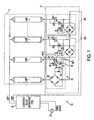
- Fig. 1 depicts a luminaire 20 comprising multiple instant start fluorescent lamps 5 (i.e., lamp 1, lamp 2,..., lamp N) connected to a single lamp instant-start fluorescent ballast 10, and circuitry 15 that allows one lamp to operate at any given time.
- lamp 1 ceases to operate
- lamp 2 begins operating and prevents conduction of current, via circuitry 15, to lamps 3 through N, for example.
- An advantage of the present invention is that the serviceable life of a luminaire 20 is extended by increasing the number of lamps N employed therein. The number of lamps is limited by the physical capacity of the luminaire 20.
- the luminaire 20 employs a power supply 25 coupled to a fluorescent ballast 10 in a conventional manner.
- the ballast 10 is preferably an instant start type such that current travels through one wire that is tied to the filament of each lamp and connected at a single point so that lamp current is routed through a single wire to facilitate operation of circuitry 30. Accordingly a single ballast 10 can operate multiple lamps 5.
- the ballast 10 is either a single lamp ballast or a multi-lamp ballast, although only one lamp operates at a given time.
- Circuitry indicated generally at 30 is coupled to lamp 1 to facilitate blocking downstream current to lamps 2-N, thus allowing only lamp 1 to operate.
- the number of circuits 30 employed by the luminaire 20 of the present invention is one less than the number of lamps 5. That is, the number of individual circuits 30 is N-1, where N is the total number of lamps 5. The last lamp N does not need accompanying circuitry 30 as there are no lamps downstream from the lamp N.
- the present invention does not facilitate operation of a specific lamp. Accordingly, it is possible that upon initial application of power, lamp 3 operates before lamp 1 or lamp 2. In such a case, lamps 1 or 2 may begin to operate, as well since they are able to conduct current. However, the ballast preferably provides a reduced open circuit voltage to lamp 1 and 2 when lamp 3 strikes and operates thus making starting an upstream lamp (e.g., lamps 1 or 2) more difficult but not impossible, as detailed below.
- an upstream lamp e.g., lamps 1 or 2
- the luminaire prevents multiple lamp rectification that occurs when the lamps 15 have aged to some unknown degree. For example, if lamp 3 is operating lamps 4-N are prevented from operating by the circuitry 15. Lamps 1 and 2, however, are still able to conduct. In this case, lamps 2 and 3 can rectify the incoming power supplied by power source 25 via ballast 10. This rectification is evident to the user by the fact that lamps 2 and 3 are turning on and off in an alternating half-wave sequence. This is an undesirable condition since it reduces the lamp life of a given lamp as material from one filament will be deposited on the other filament thus prematurely depleting the emission mix.
- Fig. 1 there are essentially three scenarios that occur in operating one of the lamps 5 of the present invention.
- lamp 1 starts to operate before any of the other lamps 2 through N.
- any lamp 2 through N can start to operate before lamp 1.
- the operating lamp approaches the end of its operating life, another lamp, either upstream or downstream of the extinguished lamp, becomes the operating lamp. This continues until all of the lamps reach the end of their operating lives. Accordingly, the service life of the luminaire 20 is extended by N, that is, the number of lamps, therein.
- Lamp 1 initiates operation in a conventional manner via ballast 10.
- Current flows from lamp 1 to the full-wave bridge rectifier 32 for rectification.
- Current from the rectifier 32 is then provided to the input of an optocoupler 40 via resistors 36 and 38.
- the resistors 36 and 38 are preferably in a parallel combination, where resistor 38 is in series with the optocoupler 40, and limit the input current to so as not to exceed the rating for the light emitting diode (LED) of optocoupler 40.
- the optocoupler 40 provides an electrically isolated signal coupled between a photothyristor and a LED in a conventional manner.
- the LED emits light when current passes through which in turn activates the photothyristor upon receiving light from the LED.
- the photothyrisotor in turn provides a low impedance current path at the output of optocoupler 40.
- the current passing through the output of optocoupler 40 prevents the gating of a triac 42.
- the octocoupler 40 is energized via current through resistor 38, thus taking the gate 44 of triac 42 to MT2 of triac 42. Accordingly, optocoupler 40 shorts, thus preventing triac 42 from conducting current to the subsequent downstream lamp 2, for example, and ensuring operation of the lamp 1. This operation occurs for each subsequent circuit 30a through N.
- the second situation occurs when any lamp other than lamp 1 operates first.
- the operating lamp disables all lamps downstream from itself in a manner consistent with an embodiment of the present invention, as described above.
- all of the lamps upstream of the operating lamp are not disabled as current is still able to flow through each of the upstream lamps.
- the upstream lamps are either at the end of their serviceable life or able to conduct. Therefore, it is possible that one or more upstream lamps will ignite if there is sufficient voltage across the lamp.
- the likelihood of such an event is reduced by the very nature of conventional fluorescent lamps 5.
- the lamps 5 need a sufficient open circuit voltage provided by the ballast 10 to initiate operation.
- the new operating lamp disables all downstream lamps from itself in a manner consistent with an embodiment of the present invention, as described above. This ensures that only one lamp operates at any given time. Accordingly, for example, if lamp 2 is initially operating, and then lamp 1 suddenly begins operating due to adequate voltage occurring across lamp 1, the present invention ensures that the operating lamp 1 disables lamp 2, thus allowing only one lamp (i.e., lamp 1) to operate.
- Resistor 48 and capacitor 50 are added to circuitry 15, as shown in Fig. 4, to stop the current in lamp 1 and lamp 2 from rectifying or becoming asymmetric, as depicted in Pig. 3.
- the voltage developed across capacitor 50 acts as a back voltage or reverse voltage across lamp 1, as compared to the voltage across ballast 10, and opposes the electromotive force (EMF) charge provided by the ballast 10, thereby reducing the net voltage across lamp 1 and terminating its operation.
- EMF electromotive force
- the first of the lamps associated with capacitors 50 or 54 i.e., lamps 1 and 2, respectively
- the capacitor 50 is sized such that the voltage drop across it is minimal during steady-state bi-directional operation.
- the resistor 48 is preferably provided as an energy discharge path in the event that a residual charge is present within capacitor 50, for example. Accordingly, any potential hazard of receiving electric shock by touching the luminaire 64 is minimized.
- Capacitors 50, 54,58, and 62 0.15 microfarads Full wave bridges 32 through FB N-1 Motorola 3N250 Optocoupler OC1 through OC N-1 Motorola MOC3023 Triac S1 through SN-1 MAC218 Resistors 36 and R1 20 ⁇ Resistors 38 and R2 470 ⁇ Resistors R3 47 k ⁇ Resistors 48, 52, 56, and 60 10 M ⁇
- circuitry 15 of Fig. 1 is preferably employed with any discharge or incandescent lamp due to the use of low-frequency ballasts in those types of luminaires. If the luminaire employs a high-frequency ballast, then the embodiment of the present invention depicted in Fig. 4 is preferred.
Landscapes
- Circuit Arrangements For Discharge Lamps (AREA)
Applications Claiming Priority (2)
| Application Number | Priority Date | Filing Date | Title |
|---|---|---|---|
| US909839 | 1992-07-07 | ||
| US09/909,839 US6483260B1 (en) | 2001-07-23 | 2001-07-23 | Apparatus for operating respective single lamps among multiple lamps coupled to the same ballast |
Publications (1)
| Publication Number | Publication Date |
|---|---|
| EP1280385A1 true EP1280385A1 (fr) | 2003-01-29 |
Family
ID=25427908
Family Applications (1)
| Application Number | Title | Priority Date | Filing Date |
|---|---|---|---|
| EP02255130A Withdrawn EP1280385A1 (fr) | 2001-07-23 | 2002-07-22 | Appareil d'operation d'une seule lampe d'une pluralité de lampes avec le même ballast |
Country Status (3)
| Country | Link |
|---|---|
| US (1) | US6483260B1 (fr) |
| EP (1) | EP1280385A1 (fr) |
| CA (1) | CA2393815A1 (fr) |
Cited By (1)
| Publication number | Priority date | Publication date | Assignee | Title |
|---|---|---|---|---|
| EP2214196A1 (fr) * | 2009-01-28 | 2010-08-04 | E.K.O. Energie Kosten Optimierung GmbH | Dispositif d'éclairage doté d'une lampe à décharge |
Families Citing this family (8)
| Publication number | Priority date | Publication date | Assignee | Title |
|---|---|---|---|---|
| KR100422448B1 (ko) * | 2001-10-11 | 2004-03-11 | 삼성전자주식회사 | 식각장치의 램프 교체 경보장치 및 그의방법 |
| JP4447885B2 (ja) * | 2003-10-24 | 2010-04-07 | 昌和 牛嶋 | 面光源装置用インバータ回路 |
| US7372215B2 (en) * | 2004-02-19 | 2008-05-13 | International Rectifier Corporation | Lamp ballast for circuit driving multiple parallel lamps |
| CN101069455A (zh) * | 2004-11-26 | 2007-11-07 | 皇家飞利浦电子股份有限公司 | 具有灯选择部件的气体放电灯驱动电路 |
| JP4318659B2 (ja) * | 2005-03-28 | 2009-08-26 | Tdk株式会社 | 放電灯駆動装置 |
| US8358087B2 (en) | 2010-06-22 | 2013-01-22 | Zilog, Inc. | Alternating turn off timing of a fluorescent lamp starter unit |
| KR102132665B1 (ko) * | 2013-03-21 | 2020-07-21 | 서울반도체 주식회사 | 이중 브리지 다이오드를 이용한 led 구동회로, 이를 포함하는 led 조명장치 |
| US20190041939A1 (en) * | 2016-10-26 | 2019-02-07 | Hewlett-Packard Development Company, L.P. | Power management |
Citations (4)
| Publication number | Priority date | Publication date | Assignee | Title |
|---|---|---|---|---|
| US4572989A (en) * | 1981-03-30 | 1986-02-25 | Patent-Treuhand Gesellschaft fur electrische Gluhlampen mbH | Rapid-start, low-pressure discharge lamp operating circuit |
| US5079485A (en) * | 1989-11-22 | 1992-01-07 | Trilux-Lenze Gmbh & Co. K.G. | Ballast for supplying a plurality of discharge lamps |
| EP0930809A2 (fr) * | 1997-12-17 | 1999-07-21 | Juan Roura y Cia., S.A. | Procédé et dispositif pour alimenter des lampes fluorescentes |
| JP2001085179A (ja) * | 1999-09-09 | 2001-03-30 | Daiwa Denki Kk | 蛍光灯用電子安定器 |
Family Cites Families (14)
| Publication number | Priority date | Publication date | Assignee | Title |
|---|---|---|---|---|
| US3676734A (en) * | 1968-11-15 | 1972-07-11 | Tokai Rika Co Ltd | Electric circuit for rapidly igniting a discharge tube |
| US3562580A (en) | 1969-01-10 | 1971-02-09 | Minnesota Mining & Mfg | Lamp-failure detection and change device |
| US3790846A (en) | 1972-12-18 | 1974-02-05 | M Morris | Automatic load monitoring and transfer circuit |
| US4475062A (en) | 1982-05-06 | 1984-10-02 | Michael Radenkovich | Economy device for fluorescent lighting fixtures |
| US4587600A (en) * | 1985-04-30 | 1986-05-06 | John Morten | Lighting fixture |
| US4862038A (en) | 1987-06-08 | 1989-08-29 | Morten John F | Automatic relamping system |
| US4945279A (en) | 1988-12-01 | 1990-07-31 | Leu Wen Fong | Lamp apparatus for generating sequential flashes |
| JP3180364B2 (ja) * | 1990-09-25 | 2001-06-25 | 東芝ライテック株式会社 | 高圧放電灯及びその点灯方法 |
| US5128595A (en) | 1990-10-23 | 1992-07-07 | Minami International Corporation | Fader for miniature lights |
| US5430354A (en) | 1992-03-24 | 1995-07-04 | North American Philips Corporation | HID lamp and auxiliary lamp ballast using a single multiple function switch |
| US5610448A (en) | 1994-07-25 | 1997-03-11 | International Energy Conservation Systems, Inc. | Universal switching device and method for lighting applications |
| US6100653A (en) * | 1996-10-16 | 2000-08-08 | Tapeswitch Corporation | Inductive-resistive fluorescent apparatus and method |
| DE19715342C1 (de) * | 1997-04-12 | 1998-12-17 | Vossloh Schwabe Gmbh | Vorschaltgerät für unabhängigen Parallelbetrieb von Niederdruck-Gasentladungslampen |
| US6157140A (en) | 1998-12-30 | 2000-12-05 | Rodrigue; Joseph Edward | Sequentially pulsed energy flow loop |
-
2001
- 2001-07-23 US US09/909,839 patent/US6483260B1/en not_active Expired - Lifetime
-
2002
- 2002-07-16 CA CA002393815A patent/CA2393815A1/fr not_active Abandoned
- 2002-07-22 EP EP02255130A patent/EP1280385A1/fr not_active Withdrawn
Patent Citations (4)
| Publication number | Priority date | Publication date | Assignee | Title |
|---|---|---|---|---|
| US4572989A (en) * | 1981-03-30 | 1986-02-25 | Patent-Treuhand Gesellschaft fur electrische Gluhlampen mbH | Rapid-start, low-pressure discharge lamp operating circuit |
| US5079485A (en) * | 1989-11-22 | 1992-01-07 | Trilux-Lenze Gmbh & Co. K.G. | Ballast for supplying a plurality of discharge lamps |
| EP0930809A2 (fr) * | 1997-12-17 | 1999-07-21 | Juan Roura y Cia., S.A. | Procédé et dispositif pour alimenter des lampes fluorescentes |
| JP2001085179A (ja) * | 1999-09-09 | 2001-03-30 | Daiwa Denki Kk | 蛍光灯用電子安定器 |
Non-Patent Citations (1)
| Title |
|---|
| PATENT ABSTRACTS OF JAPAN vol. 2000, no. 20 10 July 2001 (2001-07-10) * |
Cited By (1)
| Publication number | Priority date | Publication date | Assignee | Title |
|---|---|---|---|---|
| EP2214196A1 (fr) * | 2009-01-28 | 2010-08-04 | E.K.O. Energie Kosten Optimierung GmbH | Dispositif d'éclairage doté d'une lampe à décharge |
Also Published As
| Publication number | Publication date |
|---|---|
| US6483260B1 (en) | 2002-11-19 |
| CA2393815A1 (fr) | 2003-01-23 |
Similar Documents
| Publication | Publication Date | Title |
|---|---|---|
| US9232578B2 (en) | LED lamp with variable input power supply | |
| US7042161B1 (en) | Ballast with arc protection circuit | |
| US8362701B2 (en) | Ballast with end-of-life protection for one or more lamps | |
| WO1998049874A1 (fr) | Ballast de gradation utilise pour regler le courant alimentant une lampe fluorescente | |
| US6483260B1 (en) | Apparatus for operating respective single lamps among multiple lamps coupled to the same ballast | |
| US10959310B2 (en) | Solid-state lighting with complementary controls | |
| US8853963B2 (en) | Low current solution for illuminated switches using DC operated LEDs | |
| US8860312B2 (en) | Light emitting diodes driven by high intensity discharge ballast | |
| US10660184B2 (en) | Solid-state lighting with multiple time delays | |
| CA2429430C (fr) | Ballast a circuit de protection contre les defauts de mise a la terre de la lampe | |
| US7449840B2 (en) | Ignitor turn-off switch for HID ballasts | |
| US4475062A (en) | Economy device for fluorescent lighting fixtures | |
| US10869373B2 (en) | Solid-state lighting with highly integrated drivers | |
| CN114271030B (zh) | 用于连接到电源的基于发光二极管led的双端改型照明设备 | |
| US7282869B1 (en) | HID ballast and lamp tester | |
| US11846396B2 (en) | Linear solid-state lighting with bidirectional circuits | |
| CN108882455B (zh) | 具有无起火危险的可靠电击电流控制的线性固态照明 | |
| CN110547046B (zh) | 用于替换荧光灯的led灯装置 | |
| WO1991007070A1 (fr) | Circuit de prechauffage pour lampes a fluorescence | |
| JPH07226298A (ja) | 放電灯点灯装置および照明装置 | |
| JPH05182777A (ja) | 放電灯点灯装置およびこの点灯装置を用いた照明器具 | |
| US7573204B2 (en) | Standby lighting for lamp ballasts | |
| CN1297672A (zh) | 荧光灯的控制机构 | |
| WO1989001731A1 (fr) | Ballast electronique pour lampes fluorescentes | |
| JPS5829600B2 (ja) | 放電灯調光装置 |
Legal Events
| Date | Code | Title | Description |
|---|---|---|---|
| PUAI | Public reference made under article 153(3) epc to a published international application that has entered the european phase |
Free format text: ORIGINAL CODE: 0009012 |
|
| AK | Designated contracting states |
Designated state(s): AT BE BG CH CY CZ DE DK EE ES FI FR GB GR IE IT LI LU MC NL PT SE SK TR |
|
| AX | Request for extension of the european patent |
Extension state: AL LT LV MK RO SI |
|
| AKX | Designation fees paid | ||
| REG | Reference to a national code |
Ref country code: DE Ref legal event code: 8566 |
|
| STAA | Information on the status of an ep patent application or granted ep patent |
Free format text: STATUS: THE APPLICATION IS DEEMED TO BE WITHDRAWN |
|
| 18D | Application deemed to be withdrawn |
Effective date: 20030730 |