EP1280433B1 - System zum auftragen einer zusammensetzung auf ein flächenelement - Google Patents
System zum auftragen einer zusammensetzung auf ein flächenelement Download PDFInfo
- Publication number
- EP1280433B1 EP1280433B1 EP20010931820 EP01931820A EP1280433B1 EP 1280433 B1 EP1280433 B1 EP 1280433B1 EP 20010931820 EP20010931820 EP 20010931820 EP 01931820 A EP01931820 A EP 01931820A EP 1280433 B1 EP1280433 B1 EP 1280433B1
- Authority
- EP
- European Patent Office
- Prior art keywords
- receptacle
- main body
- applicator
- composition
- container
- Prior art date
- Legal status (The legal status is an assumption and is not a legal conclusion. Google has not performed a legal analysis and makes no representation as to the accuracy of the status listed.)
- Expired - Lifetime
Links
- 239000000203 mixture Substances 0.000 title claims abstract description 70
- 239000006260 foam Substances 0.000 claims description 10
- 239000002775 capsule Substances 0.000 claims description 3
- 230000000149 penetrating effect Effects 0.000 claims description 3
- 239000012528 membrane Substances 0.000 claims 2
- 239000002537 cosmetic Substances 0.000 description 5
- 208000031968 Cadaver Diseases 0.000 description 4
- 239000002904 solvent Substances 0.000 description 3
- 238000003780 insertion Methods 0.000 description 2
- 230000037431 insertion Effects 0.000 description 2
- 239000002991 molded plastic Substances 0.000 description 2
- 239000004033 plastic Substances 0.000 description 2
- 229920003023 plastic Polymers 0.000 description 2
- 239000000047 product Substances 0.000 description 2
- 241000239290 Araneae Species 0.000 description 1
- 239000004698 Polyethylene Substances 0.000 description 1
- 238000004026 adhesive bonding Methods 0.000 description 1
- 238000006073 displacement reaction Methods 0.000 description 1
- 239000003814 drug Substances 0.000 description 1
- 229940079593 drug Drugs 0.000 description 1
- 238000001704 evaporation Methods 0.000 description 1
- 238000005470 impregnation Methods 0.000 description 1
- 239000007788 liquid Substances 0.000 description 1
- 239000000463 material Substances 0.000 description 1
- 239000012466 permeate Substances 0.000 description 1
- -1 polyethylene Polymers 0.000 description 1
- 229920000573 polyethylene Polymers 0.000 description 1
- 229920002635 polyurethane Polymers 0.000 description 1
- 239000004814 polyurethane Substances 0.000 description 1
- 239000011148 porous material Substances 0.000 description 1
- 230000000284 resting effect Effects 0.000 description 1
- 239000007787 solid Substances 0.000 description 1
Images


Classifications
-
- A—HUMAN NECESSITIES
- A45—HAND OR TRAVELLING ARTICLES
- A45D—HAIRDRESSING OR SHAVING EQUIPMENT; EQUIPMENT FOR COSMETICS OR COSMETIC TREATMENTS, e.g. FOR MANICURING OR PEDICURING
- A45D34/00—Containers or accessories specially adapted for handling liquid toiletry or cosmetic substances, e.g. perfumes
- A45D34/04—Appliances specially adapted for applying liquid, e.g. using roller or ball
- A45D34/042—Appliances specially adapted for applying liquid, e.g. using roller or ball using a brush or the like
- A45D34/045—Appliances specially adapted for applying liquid, e.g. using roller or ball using a brush or the like connected to the cap of the container
-
- A—HUMAN NECESSITIES
- A45—HAND OR TRAVELLING ARTICLES
- A45D—HAIRDRESSING OR SHAVING EQUIPMENT; EQUIPMENT FOR COSMETICS OR COSMETIC TREATMENTS, e.g. FOR MANICURING OR PEDICURING
- A45D40/00—Casings or accessories specially adapted for storing or handling solid or pasty toiletry or cosmetic substances, e.g. shaving soaps or lipsticks
- A45D40/0087—Casings or accessories specially adapted for storing or handling solid or pasty toiletry or cosmetic substances, e.g. shaving soaps or lipsticks for samples
-
- A—HUMAN NECESSITIES
- A45—HAND OR TRAVELLING ARTICLES
- A45D—HAIRDRESSING OR SHAVING EQUIPMENT; EQUIPMENT FOR COSMETICS OR COSMETIC TREATMENTS, e.g. FOR MANICURING OR PEDICURING
- A45D2200/00—Details not otherwise provided for in A45D
- A45D2200/10—Details of applicators
- A45D2200/1009—Applicators comprising a pad, tissue, sponge, or the like
- A45D2200/1018—Applicators comprising a pad, tissue, sponge, or the like comprising a pad, i.e. a cushion-like mass of soft material, with or without gripping means
Definitions
- the present invention relates to an application system transportable intended in particular to apply a composition to a localized surface element. More particularly, the present invention relates to a disposable application system after a few uses.
- a field of application envisaged is notably but not exclusively that of makeup.
- the user after unlocking the handle forming a cylindrical reservoir cap, remove the applicator impregnated with the composition to apply the latter to the place longed for.
- a device according to the preamble of claim 1 is known from document US-A-4206843.
- a first object of the present invention is to provide a system for applying a cosmetic composition, containing a low volume of said composition stored hermetically in the system and which is inexpensive to produce.
- composition to be applied is contained in a reservoir likely to be punctured.
- This type of standard tank can contain a wide variety of compositions in small quantities and they are perfectly airtight. Furthermore, they have the advantage of being easily punctured to release the composition they contain.
- the reservoir is inserted into a receptacle having the shape of a cylindrical tank according to the prior art but that it is no longer this receptacle must be hermetically closed by an element of the applicator forming a cap since the perforable reservoir is itself hermetic. So, are the costs of producing such a receptacle lower than the costs of making a cylindrical tank classic.
- the system includes means of application at the end of the main body which is capable of being engaged in the receptacle.
- the system also includes means for perforate the reservoir in order to impregnate the means of application and these means are implemented by the forced insertion of the main body in the receptacle.
- the application system comprises in in addition to deformable connecting means able to hold said body main in said receptacle and to guide it when the main body is forced into said receptacle to cause perforation of said reservoir and wear said application means near said reservoir perforated.
- the main body and the receptacle can be made of molded plastic.
- the means for cause the perforation of said perforable reservoir are located nearby of said tank so as to be driven against said tank for the perforate when said main body, bearing on said means to cause perforation, is forced into said receptacle.
- the means for causing the perforation of the reservoir are located between the tank and the main body when introduced in the receptacle. So when the main body is pushed into the receptacle, it drives the means to cause the perforation which compress the surface of the tank to puncture it.
- the application system further comprises a transfer element of said composition located between said perforable reservoir and said means suitable for capillary transfer of said composition of the reservoir perforated to said application means.
- This characteristic allows a distribution of the composition that contains the perforable reservoir, when perforated, on the means homogeneous application.
- the connecting means deformable include fracturable fastening means, suitable for be fractured by forcing said main body into said receptacle by which said main body is held in a fixed position in said receptacle.
- This advantageous characteristic makes it possible to temporarily fix the main body in the receptacle before using the system. So, only when the main body is pushed into the receptacle to perforate the tank that the fracturable fixing means are broken. This feature also ensures that the tank has not been punctured before.
- the means for cause the perforation of said perforable tank consist of a sleeve capable of sliding in said receptacle, said sleeve comprising, at one of its ends, grid-forming means, and being placed so that the end with the grid means is located opposite said perforable tank and in that said body main is able to bear on the other of said ends of said sleeve, said application means penetrating at least partially in said sleeve.
- the perforable reservoir is first introduced into the bottom of the receptacle then the sleeve is slid into the receptacle so that the grid means are near the tank.
- the tank has a diameter significantly smaller than the diameter of the receptacle and that the sleeve has a diameter substantially equal to that of the tank.
- the main body which is held against the sleeve is capable of driving it so that the means forming a grid perforate the tank.
- the transfer means consist of a foam element housed in said sleeve, so that said element foam is in contact with the means of application and with said composition, which passes through said grid means when said perforable tank is perforated.
- the foam element housed in the sleeve is in contact with the application means since it penetrates at least partially in said sleeve.
- the main body When the main body is pushed in in the receptacle, it rests on the edge of the sleeve and causes the support of the grid-forming means on the reservoir which pierces it when the depth is sufficiently large. Since the means are in contact with the foam element and that the composition migrates into said foam element through the means forming a grid, the application means are impregnated with the composition contained in the tank.
- the application means and said means for causing the perforation of said tank constitute a single piece. So by a choice appropriate to the nature of the means of application and in particular their hardness, they are able to perforate the tank directly by pressing of the main body in the receptacle.
- the means for causing the perforation of said reservoir are connected to said receptacle by said deformable connecting means. So, the translational drive of the main body which is free relative to the receptacle, drives the means to cause perforation in deforming the deformable connecting means.
- said perforable reservoir consists of a closed fracturable capsule containing the said composition.
- the tank is produced in large series and can be introduced into the application system during assembly.
- said perforable reservoir is formed by said closed receptacle, between the bottom of said receptacle and its open end, by a fracturable cover, said composition being contained between said bottom and said cover.
- the internal wall of the receptacle constitutes a substantial part of the tank wall, which is not punctured.
- the perforable part being constituted by a fracturable lid maintained tightly against the inner wall of the receptacle and trapping the composition in the bottom of the receptacle.
- said main body has a first part presenting said means application, and a second removable part comprising said rod.
- the second part is likely to be joined together or disconnected from the first part.
- said first part of said main body comprising said application means is integral with said means to cause perforation.
- the first part of the main body is integral with the receptacle, the second part comprising the rod being capable of being mounted on the first part.
- a second object of the present invention is to provide a transportable application set, comprising a plurality of transportable application systems, said receptacles comprising each a composition, each receptacle comprising means for cause the perforation of said reservoir and a first part of said body main equipped with said application means; and said second part comprising said rod is capable of being mounted on the first parts provided with said application means for perforating said reservoir perforable and impregnate them with the composition. So the second part of the main body extended by the rod is removable and only one second part is necessary for the application of the different compositions contained in the plurality of transportable application systems.
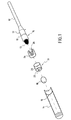
- the system comprises a main body 10 of symmetry cylindrical, extended by a gripping rod 12 whose diameter is lower than the main body 10.
- the gripping rod 12 and the body 5 main 10 constitute one and the same plastic part likely to be molded.
- the main body 10 is provided with application means 13 to its end.
- These application means 13 made of foam, of symmetry cylindrical, allow the composition to be applied to an element of localized surface and to do this they present a tapered end of ogival shape.
- the foam used is preferably extremely soft, so as not to irritate the skin of the user applying the composition on his skin.
- the system also includes a receptacle 14, or plug, also of cylindrical symmetry and having a first end open and a second end closed.
- Main body 10 of system is capable of being introduced into receptacle 14 and of closing it first end open.
- the main body 10 has an external diameter substantially smaller than the internal diameter of the receptacle 14. Furthermore, the application system further comprises connecting means deformable to hold the main body 10 in the receptacle 14.
- These connecting means comprise a groove 15 formed around the main body 10 cooperating with a rib 16 located on the internal wall of the receptacle 14.
- the main body 10 and receptacle 14 are made of molded plastic, which allows to obtain a relative elasticity of the groove 15 and the rib 16 leading to an elastically deformable connection.
- the deformable connecting means comprise ) fracturable fastening means 17 resting on the edge of the end receptacle open 14.
- the total introduction of the main body 10 into the receptacle 14 is only possible when the fixing means fracturables 17 are broken.
- the fixing means fracturables are only connected to main body 10, but they can also be integral with the edge of the end of the receptacle 14 when the system is mounted.
- the main body 10 is held in position fixed relative to receptacle 14 and testifies to non-use system.
- the application system is intended to apply a composition that it contains, in particular cosmetic compositions.
- These compositions are generally liquid and can be stored in a substantially spherical tank whose capacity is of the order of milliliter or tenth of a milliliter.
- These tanks usually in polyurethane or polyethylene type plastic, are likely to be punctured or burst under pressure exerted on their wall, in order to release the contents.
- These tanks are also hermetic towards the solvents which are generally there introduced.
- the application system comprises a perforable reservoir 18 in which the composition to be applied has been introduced.
- the perforable reservoir 18 containing the composition is disposed in the bottom of the receptacle 14.
- it is fixed by gluing to the bottom wall of the receptacle 14, but it can also be left free since the other elements of the application system that we will describe below obstruct the receptacle 14 and trap the reservoir perforable 18.
- the receptacle 14 also comprises means 19 for cause the perforation of the reservoir 18, located above it so that the reservoir 18 is interposed between the bottom wall of the receptacle 14 and the means 19 for causing its perforation.
- the means 19 for causing the perforation of the reservoir perforable 18 consist of a sleeve 20 whose external diameter is significantly smaller than the internal diameter of the receptacle 14 so that he can slide there. They also consist of means 22 forming a grid attached to the end of the sleeve 20 so that the plane means of said grid forming means 22 are perpendicular to the axis of the sleeve 20.
- the means 22 forming a grid consist of a spider comprising three branches, the ends of which are connected to the edge of one of the ends of the sleeve 20. Of course, any other form of means 22 forming a grid would be suitable.
- the means for causing the perforation 19 are introduced into the receptacle 14 above the perforable reservoir 18 so that the end of the sleeve 20 comprising the cross is facing the perforable tank 18.
- the application system according to the invention further comprises a transfer element 24 of the composition, made of porous material.
- This foam transfer element 24 is of cylindrical symmetry and its dimensions are such that it fits entirely in the sleeve 20, leaning at one of its ends on the grid forming means 22.
- the transfer element 24 comprises an axial channel intended to allow easier transfer of the composition by capillarity.
- the main body 10 is forced into the receptacle 14.
- the main body 10 is forced into receptacle 14 first causes the fracturing of the fracturable fastening means which are separated from the main body 10. Then the main body 10 is applied against the edge of the sleeve 20 and the application means 13 against the transfer element 24.
- the solid support of the main body 10 on the sleeve 20 drives the latter and the means 22 forming a grid against the perforable tank 18 which bears against the bottom wall of the receptacle 14.
- the grid means 22 perforate the wall of the perforable reservoir 18 releasing the composition it contains.
- the composition permeates the transfer element 24 which, by capillarity, the transmits to the application means 13. Maintaining the main body 10 in the receptacle 14 after the forced insertion must last for one time long enough, on the order of a second, to allow a good impregnation. Due to the tapered shape of the application means 13 which cooperate with the transfer element 24 having a recess 26, the composition uniformly covers the surface of the means 13 in contact with the transfer element 24. Thus, the composition is more easily applicable on the surface considered.
- the application system After first use, the application system is likely to be reused a second time if the composition has not been totally transferred to the application means 13. To do this, the body main 10 is reintroduced into receptacle 14. The second use may not take place immediately after the premiere, and the means to deformable connection, in particular the groove 15 and the rib 16, keep the main body 10 in the receptacle 14 until the time of this second use without the solvent of the composition does not evaporate.
- the means of application and the means to cause the perforation of the tank constitute one and the same room.
- the application means are made of a material relatively rigid so as to be able to perforate the perforable reservoir containing the composition without any other additional part.
- the application system according to the invention essentially relates disposable systems for composition applications cosmetics or for drug compositions.
- the present invention also relates to a transportable application set, comprising a plurality of transportable application systems, which will be described with reference to Figures 5 and 6.
- Figure 1 illustrates an application system with a receptacle 38 and a removable main body having a first part 40 provided with application means 42, and a second part 44 comprising said rod.
- the second part 44 is likely to be screwed on the first part 40 which is itself engaged in means 46 to cause the perforation of a perforable reservoir 48, said reservoir perforable 48 being formed by the receptacle 38 itself.
- Composition 50 is contained in the bottom of the receptacle which is closed by a fracturable cover 52.
- the edge of the cover fracturable 52 is applied hermetically against the internal wall of the receptacle so as to isolate the composition 50 from the exterior of the receptacle 38.
- the means 46 for causing the perforation of said reservoir 48 are connected to said receptacle 38 by deformable connecting means 54 and said first part 40 of said main body comprising said application means 42 is integral with said means for causing the perforation 46.
- the second part 44 of the main body is likely to be mounted on the second part 40 and the displacement at force of the main body in the receptacle drives the means for cause perforation 46 and deformation of the connecting means deformable 54.
- the fracturable cover 52 located nearby means for causing the perforation 46 is perforated and the means 42 are driven into contact with the composition 50 to be permeated.
- the main body is removed from the receptacle 38 by means of the second part 44 of the main body extended by the rod.
- FIG. 6 illustrates an application package according to the invention, said receptacles 38 being inserted in a housing 56.
- Each receptacle 38 includes means for causing the perforation of said reservoir and a first part of said main body 40 appearing in Figure 6 provided with said application means.
- said second part 44 comprising said rod is disposed in the housing 56 to proximity to receptacles 38.
- the application assembly transportable is likely to contain a plurality of receptacles containing different compositions to be applied, their application being independently performed by means of the second part 44 which is mounted for this purpose on one of the first part 40 constituting the body main.
- the perforable tank consists a closed, breakable capsule containing said composition and it is arranged in the bottom of the receptacle.
- the application assembly according to the invention is intended to receive both medicinal compositions and cosmetic compositions.
Landscapes
- Containers And Packaging Bodies Having A Special Means To Remove Contents (AREA)
- Coating Apparatus (AREA)
- Closures For Containers (AREA)
- Paints Or Removers (AREA)
- Mechanical Treatment Of Semiconductor (AREA)
Claims (14)
- Transportables Aufbringungssystem, das insbesondere dazu bestimmt ist, eine Zusammensetzung auf ein lokalisiertes Oberflächenelement aufzubringen, umfassend einen Hauptkörper (10), der durch eine Greifstange verlängert ist, ein Gehäuse (14), in das der Hauptkörper (10) eingeführt werden kann,
einen die Zusammensetzung enthaltenden perforierbaren Behälter (18), der in dem Gehäuse (14) gehalten wird, und
Mittel (13) zum Aufbringen der Zusammensetzung, die mit dem Ende des Hauptkörpers (10) verbunden sind,
dadurch gekennzeichnet,dass es Mittel umfasst, um die Perforation (19) des Behälters (18) hervorzurufen, wenn der Hauptkörper (10) fest in das Gehäuse (14) gedrückt wird, um den perforierbaren Behälter (18) zu perforieren, wodurch die Aufbringungsmittel (13) mit der Zusammensetzung durchsetzt werden können. - Transportables Aufbringungssystem nach Anspruch 1, dadurch gekennzeichnet, dass es ferner verformbare Verbindungsmittel (15, 16, 17) umfasst, die den Hauptkörper (10) in dem Gehäuse (14) halten und ihn führen können, wenn der Hauptkörper (10) fest in das Gehäuse (14) gedrückt wird, um die Perforation des Behälters (18) hervorzurufen und die Aufbringungsmittel (13) in die Nähe des perforierten Behälters (18) zu bringen.
- Transportables Aufbringungssystem nach Anspruch 2, dadurch gekennzeichnet, dass die Mittel zum Hervorrufen der Perforation des Behälters (18) mit dem Gehäuse (14) durch die verformbaren Verbindungsmittel verbunden sind.
- Transportables Aufbringungssystem nach Anspruch 2 oder 3, dadurch gekennzeichnet, dass die verformbaren Verbindungsmittel brechbare Befestigungsmittel (17) umfassen, die durch das feste Eindrücken des Hauptkörpers (10) in den Behälter (14) gebrochen werden können, wodurch der Hauptkörper (10) in dem Gehäuse (14) in fester Position gehalten wird.
- Transportables Aufbringungssystem nach einem der Ansprüche 1 bis 4, dadurch gekennzeichnet, dass die Mittel zum Hervorrufen der Perforation (19) des perforierbaren Behälters (18) in der Nähe des Behälters (18) angeordnet sind, um gegen den Behälter (18) getrieben zu werden, um ihn zu perforieren, wenn der Hauptkörper (10), der auf den Mitteln zum Hervorrufen der Perforation (19) aufliegt, fest in das Gehäuse (14) gedrückt wird.
- Transportables Aufbringungssystem nach einem der Ansprüche 1 bis 5, dadurch gekennzeichnet, dass die Mittel zum Hervorrufen der Perforation (19) des perforierbaren Behälters von einer Hülse (20) gebildet sind, die in dem Gehäuse (14) gleiten kann, wobei die Hülse (20) an einem ihrer Enden Mittel, die ein Gitter (22) bilden, umfasst und derart angeordnet ist, dass das Ende, das die ein Gitter (22) bildenden Mittel umfasst, gegenüber dem perforierbaren Behälter (18) angeordnet sind und dass der Hauptkörper (10) auf dem anderen der Enden der Hülse (20) aufliegen kann, wobei die Aufbringungsmittel (13) zumindest teilweise in die Hülse eindringen.
- Transportables Aufbringungssystem nach einem der Ansprüche 1 bis 3, dadurch gekennzeichnet, dass es ferner sich zwischen dem perforierbaren Behälter (18) und den Aufbringungsmitteln (13) befindende Mittel (24) zur Weiterleitung der Zusammensetzung umfasst, die die Zusammensetzung durch Kapillarität vom perforierten Behälter (18) zu den Aufbringungsmitteln (13) weiterleiten können.
- Transportables Aufbringungssystem nach Anspruch 7, dadurch gekennzeichnet, dass die Weiterleitungsmittel (24) von einem Schaumelement gebildet sind, das in der Hülse (20) derart angeordnet ist, dass sich das Schaumelement mit den Aufbringungsmitteln (13) und der Zusammensetzung, die durch die ein Gitter (22) bildenden Mittel hindurchgeht, in Kontakt befindet, wenn der perforierbare Behälter (18) perforiert wird.
- Transportables Aufbringungssystem nach einem der Ansprüche 1 bis 5, dadurch gekennzeichnet, dass die Aufbringungsmittel (13) und die Mittel zum Hervorrufen der Perforation (19) des Behälters (18) ein einziges und selbes Stück bilden.
- Transportables Aufbringungssystem nach einem der Ansprüche 1 bis 9, dadurch gekennzeichnet, dass der perforierbare Behälter (18) von einer brechbaren geschlossenen Kapsel gebildet ist, die die Zusammensetzung enthält.
- Aufbringungssystem nach einem der Ansprüche 1 bis 9, dadurch gekennzeichnet, dass der perforierbare Behälter von dem Gehäuse (38) gebildet wird, das zwischen dem Boden des Gehäuses und seinem offenen Ende von einem brechbaren Innenhütchen (52) verschlossen ist, wobei die Zusammensetzung (50) zwischen dem Boden und dem Innenhütchen (52) enthalten ist.
- Transportables Aufbringungssystem nach einem der Ansprüche 1 bis 11, dadurch gekennzeichnet, dass der Hauptkörper einen ersten Teil (40), der die Aufbringungsmittel (42) umfasst, und einen demontierbaren zweiten Teil (44), der die Stange umfasst, aufweist.
- Transportables Aufbringungssystem nach Anspruch 12, dadurch gekennzeichnet, dass der erste Teil (40) des Hauptkörpers, der die Aufbringungsmittel (42) umfasst, mit den Mitteln zum Hervorrufen der Perforation (46) verbunden ist.
- Transportable Aufbringungseinheit, dadurch gekennzeichnet, dass sie ein transportables Aufbringungssystem nach Anspruch 12 oder 13 und ein oder mehrere solcher Systeme, die den demontierbaren zweiten Teil (44) nicht aufweisen, umfasst, wobei die Gehäuse (38) jeweils eine Zusammensetzung umfassen, wobei jedes Gehäuse (38) Mittel zum Hervorrufen der Perforation des Behälters und einen ersten Teil des Hauptkörpers umfasst, der mit den Aufbringungsmitteln versehen ist;
und dass der zweite Teil (44), der die Stange umfasst, auf den ersten Teilen (40), die mit den Aufbringungsmitteln versehen sind, befestigt werden kann, um den perforierbaren Behälter zu perforieren und sie mit der Zusammensetzung zu durchsetzen.
Applications Claiming Priority (3)
| Application Number | Priority Date | Filing Date | Title |
|---|---|---|---|
| FR0005874 | 2000-05-09 | ||
| FR0005874A FR2808662B1 (fr) | 2000-05-09 | 2000-05-09 | Systeme d'application d'une composition sur un element de surface |
| PCT/FR2001/001393 WO2001084977A1 (fr) | 2000-05-09 | 2001-05-09 | Systeme d'application d'une composition sur un element de surface |
Publications (2)
| Publication Number | Publication Date |
|---|---|
| EP1280433A1 EP1280433A1 (de) | 2003-02-05 |
| EP1280433B1 true EP1280433B1 (de) | 2004-10-27 |
Family
ID=8850009
Family Applications (1)
| Application Number | Title | Priority Date | Filing Date |
|---|---|---|---|
| EP20010931820 Expired - Lifetime EP1280433B1 (de) | 2000-05-09 | 2001-05-09 | System zum auftragen einer zusammensetzung auf ein flächenelement |
Country Status (8)
| Country | Link |
|---|---|
| US (1) | US6811342B2 (de) |
| EP (1) | EP1280433B1 (de) |
| JP (1) | JP4010812B2 (de) |
| AT (1) | ATE280519T1 (de) |
| AU (1) | AU2001258513A1 (de) |
| DE (1) | DE60106750D1 (de) |
| FR (1) | FR2808662B1 (de) |
| WO (1) | WO2001084977A1 (de) |
Cited By (1)
| Publication number | Priority date | Publication date | Assignee | Title |
|---|---|---|---|---|
| EP4351383A4 (de) * | 2021-06-11 | 2025-04-23 | ELC Management LLC | Probenahmesystem für kosmetische produkte |
Families Citing this family (18)
| Publication number | Priority date | Publication date | Assignee | Title |
|---|---|---|---|---|
| US6406451B1 (en) * | 2001-05-24 | 2002-06-18 | Zila, Inc. | Dry handle swab assembly |
| US20070183836A1 (en) * | 2006-02-03 | 2007-08-09 | Lampe John K | Wipe applicatior |
| US20070282241A1 (en) * | 2006-05-31 | 2007-12-06 | Squires Meryl J | Applicator system |
| US8783451B2 (en) * | 2011-02-18 | 2014-07-22 | Allergan, Inc. | Unit dose breakable vial with integrated brush applicator |
| US8262302B1 (en) * | 2011-12-20 | 2012-09-11 | Elc Management Llc | Kit for a heating applicator and product |
| IL283432B2 (en) | 2013-08-21 | 2025-02-01 | Verrica Pharmaceuticals Inc | Compositions, methods and systems for treating skin disorders |
| JP6898241B2 (ja) | 2015-01-20 | 2021-07-07 | ヴェリカ ファーマシューティカルズ, インコーポレイテッドVerrica Pharmaceuticals, Inc. | 医薬品グレードカンタリジンの定量および調製 |
| US9781991B1 (en) | 2016-03-16 | 2017-10-10 | Elc Management Llc | Heating applicator system with reusable components |
| MX393574B (es) | 2017-06-06 | 2025-03-24 | Verrica Pharmaceuticals Inc | Tratamiento de trastornos cutaneos |
| USD900312S1 (en) | 2017-06-15 | 2020-10-27 | Verrica Pharmaceuticals, Inc. | Applicator |
| WO2018232277A1 (en) | 2017-06-15 | 2018-12-20 | Verrica Pharmaceuticals, Inc. | Devices and methods for the treatment of body surface disorders |
| US20200270269A1 (en) | 2017-10-04 | 2020-08-27 | Verrica Pharmaceuticals, Inc. | Synthesis of cantharidin |
| WO2022251363A1 (en) * | 2021-05-27 | 2022-12-01 | L'oreal | Applicator having three-dimensional surface contact with reservoir |
| US20220378171A1 (en) * | 2021-05-27 | 2022-12-01 | L'oreal | Applicator having three-dimensional surface contact with reservoir |
| FR3125689B1 (fr) * | 2021-07-30 | 2023-09-08 | Oreal | Applicateur ayant un contact de surface tridimensionnel avec un reservoir |
| US11896113B2 (en) | 2021-06-11 | 2024-02-13 | Elc Management Llc | Cosmetic product sampling system |
| US11737545B2 (en) | 2021-06-11 | 2023-08-29 | Elc Management Llc | Cosmetic product sampling system |
| US20220395072A1 (en) * | 2021-06-11 | 2022-12-15 | Elc Management Llc | Cosmetic Product Sampling System |
Family Cites Families (10)
| Publication number | Priority date | Publication date | Assignee | Title |
|---|---|---|---|---|
| DE850341C (de) * | 1950-04-15 | 1952-09-25 | Gazzoni & Co A | Vorrichtung zum Benetzen des aeusseren Gehoerganges mit einer schmerzstillenden Fluessigkeit |
| US3450129A (en) * | 1966-07-06 | 1969-06-17 | Medical Supply Co | Swabbing unit |
| US3786820A (en) * | 1973-02-20 | 1974-01-22 | R Kopfer | Mixer and applicator for fingernail repair material |
| US4206843A (en) * | 1978-06-15 | 1980-06-10 | Rainey Rhett K | Cauterizing system |
| US4211323A (en) * | 1978-12-01 | 1980-07-08 | California Medical Developments, Inc. | Disposable diagnostic swab having a stored culture medium |
| US4747719A (en) * | 1986-07-28 | 1988-05-31 | Cole Parkin | Swab applicator |
| US4957385A (en) * | 1990-04-26 | 1990-09-18 | Primary Delivery Systems, Inc. | Ampule solution dispenser applicator |
| US5120301A (en) * | 1990-06-15 | 1992-06-09 | Wu Shuenn R | Self-contained swab |
| US5445462A (en) * | 1993-08-03 | 1995-08-29 | Medi-Flex Hospital Products, Inc. | Liquid applicator |
| WO1997019721A1 (fr) * | 1995-11-24 | 1997-06-05 | Charles Penalba | Dispositif permettant d'imbiber de façon prophylactique un liquide medicamenteux sur un tampon de soins |
-
2000
- 2000-05-09 FR FR0005874A patent/FR2808662B1/fr not_active Expired - Fee Related
-
2001
- 2001-05-09 WO PCT/FR2001/001393 patent/WO2001084977A1/fr not_active Ceased
- 2001-05-09 US US10/258,590 patent/US6811342B2/en not_active Expired - Fee Related
- 2001-05-09 AU AU2001258513A patent/AU2001258513A1/en not_active Abandoned
- 2001-05-09 DE DE60106750T patent/DE60106750D1/de not_active Expired - Lifetime
- 2001-05-09 EP EP20010931820 patent/EP1280433B1/de not_active Expired - Lifetime
- 2001-05-09 AT AT01931820T patent/ATE280519T1/de not_active IP Right Cessation
- 2001-05-09 JP JP2001581645A patent/JP4010812B2/ja not_active Expired - Fee Related
Cited By (1)
| Publication number | Priority date | Publication date | Assignee | Title |
|---|---|---|---|---|
| EP4351383A4 (de) * | 2021-06-11 | 2025-04-23 | ELC Management LLC | Probenahmesystem für kosmetische produkte |
Also Published As
| Publication number | Publication date |
|---|---|
| DE60106750D1 (de) | 2004-12-02 |
| EP1280433A1 (de) | 2003-02-05 |
| FR2808662A1 (fr) | 2001-11-16 |
| AU2001258513A1 (en) | 2001-11-20 |
| WO2001084977A1 (fr) | 2001-11-15 |
| US6811342B2 (en) | 2004-11-02 |
| JP4010812B2 (ja) | 2007-11-21 |
| JP2003532468A (ja) | 2003-11-05 |
| US20030105425A1 (en) | 2003-06-05 |
| FR2808662B1 (fr) | 2002-12-20 |
| ATE280519T1 (de) | 2004-11-15 |
Similar Documents
| Publication | Publication Date | Title |
|---|---|---|
| EP1280433B1 (de) | System zum auftragen einer zusammensetzung auf ein flächenelement | |
| EP0667301B1 (de) | Ausgabevorrichtung für Flüssigkeiten oder Pulver | |
| FR2790948A1 (fr) | Dispositif de transfert bidirectionnel d'un liquide entre un flacon et une capsule | |
| CA2908800C (fr) | Flacon de conditionnement de liquide | |
| CA3072412A1 (fr) | Dispositif de conditionnement d'objet, ensemble et procede d'extraction correspondant | |
| EP0797940A1 (de) | Vorrichtung zum Auftragen von flüssigen oder weichen Produkten | |
| EP1086902A1 (de) | Vorrichtung zur getrennten Aufbewahrung und zur Mischung von zwei Produkten und zum Abgeben der Mischung | |
| EP2705866A1 (de) | Vorrichtung zur Schmerzreduzierung bei der Einführung einer Spritzennadel in die Haut | |
| EP4337561B1 (de) | Spender für flüssige produkte | |
| EP1027092A1 (de) | Gerät zum auftragen von flüssigkeiten auf die haut | |
| EP1487530A1 (de) | Applikator für flüssige produkte | |
| FR2953376A1 (fr) | Ensemble pour l'application d'un produit cosmetique, notamment capillaire, sur une meche de fibres keratiniques | |
| EP1180052A1 (de) | Kartusche zum aufbewahren und auftragen einer flüssigkeit auf die haut | |
| WO2017077244A1 (fr) | Dispositif de conditionnement pour un produit à distribuer, notamment pour un parfum | |
| FR2766163A1 (fr) | Bouchon a extraction facile et son extracteur | |
| FR3014856A1 (fr) | Dispositf d'obturation d'un recipient presentant un col | |
| WO2005042371A1 (fr) | Ensemble de distribution de produit fluide | |
| EP2785614B1 (de) | Kapsel zur extraktion eines unter druck stehenden getränks | |
| EP1600385A1 (de) | Aufbewahrungs- und Ausgabevorrichtung für flüssige Produkte | |
| EP3917684B1 (de) | Anordnung zur ausgabe eines flüssigen produkts | |
| WO2017109366A1 (fr) | Pot de cosmétique comportant un système de mise sous pression d'un réservoir de réserve de produit | |
| BE853704A (fr) | Dispositif destine a prelever un volume predetermine de sang et a le melanger a un reactif ou autre produit | |
| FR2889056A1 (fr) | Dispositif portable individuel pour bain d oeil | |
| EP0537282A1 (de) | Vorrichtung zum getrennten aufbewahren zweier bestandteile und zum mischen derselben beim gebrauch. | |
| WO2000026095A1 (fr) | Contenant distributeur pour liquide, plus ou moins visqueux |
Legal Events
| Date | Code | Title | Description |
|---|---|---|---|
| PUAI | Public reference made under article 153(3) epc to a published international application that has entered the european phase |
Free format text: ORIGINAL CODE: 0009012 |
|
| 17P | Request for examination filed |
Effective date: 20021024 |
|
| AK | Designated contracting states |
Designated state(s): AT BE CH CY DE DK ES FI FR GB GR IE IT LI LU MC NL PT SE TR |
|
| AX | Request for extension of the european patent |
Extension state: AL LT LV MK RO SI |
|
| GRAH | Despatch of communication of intention to grant a patent |
Free format text: ORIGINAL CODE: EPIDOS IGRA |
|
| 18D | Application deemed to be withdrawn |
Effective date: 20031008 |
|
| D18D | Application deemed to be withdrawn (deleted) | ||
| GRAS | Grant fee paid |
Free format text: ORIGINAL CODE: EPIDOSNIGR3 |
|
| GRAA | (expected) grant |
Free format text: ORIGINAL CODE: 0009210 |
|
| AK | Designated contracting states |
Kind code of ref document: B1 Designated state(s): AT BE CH CY DE DK ES FI FR GB GR IE IT LI LU MC NL PT SE TR |
|
| PG25 | Lapsed in a contracting state [announced via postgrant information from national office to epo] |
Ref country code: IT Free format text: LAPSE BECAUSE OF FAILURE TO SUBMIT A TRANSLATION OF THE DESCRIPTION OR TO PAY THE FEE WITHIN THE PRESCRIBED TIME-LIMIT;WARNING: LAPSES OF ITALIAN PATENTS WITH EFFECTIVE DATE BEFORE 2007 MAY HAVE OCCURRED AT ANY TIME BEFORE 2007. THE CORRECT EFFECTIVE DATE MAY BE DIFFERENT FROM THE ONE RECORDED. Effective date: 20041027 Ref country code: GB Free format text: LAPSE BECAUSE OF FAILURE TO SUBMIT A TRANSLATION OF THE DESCRIPTION OR TO PAY THE FEE WITHIN THE PRESCRIBED TIME-LIMIT Effective date: 20041027 Ref country code: FI Free format text: LAPSE BECAUSE OF NON-PAYMENT OF DUE FEES Effective date: 20041027 Ref country code: IE Free format text: LAPSE BECAUSE OF FAILURE TO SUBMIT A TRANSLATION OF THE DESCRIPTION OR TO PAY THE FEE WITHIN THE PRESCRIBED TIME-LIMIT Effective date: 20041027 Ref country code: NL Free format text: LAPSE BECAUSE OF FAILURE TO SUBMIT A TRANSLATION OF THE DESCRIPTION OR TO PAY THE FEE WITHIN THE PRESCRIBED TIME-LIMIT Effective date: 20041027 Ref country code: AT Free format text: LAPSE BECAUSE OF FAILURE TO SUBMIT A TRANSLATION OF THE DESCRIPTION OR TO PAY THE FEE WITHIN THE PRESCRIBED TIME-LIMIT Effective date: 20041027 Ref country code: TR Free format text: LAPSE BECAUSE OF FAILURE TO SUBMIT A TRANSLATION OF THE DESCRIPTION OR TO PAY THE FEE WITHIN THE PRESCRIBED TIME-LIMIT Effective date: 20041027 |
|
| REG | Reference to a national code |
Ref country code: CH Ref legal event code: EP |
|
| REG | Reference to a national code |
Ref country code: IE Ref legal event code: FG4D Free format text: FRENCH |
|
| REF | Corresponds to: |
Ref document number: 60106750 Country of ref document: DE Date of ref document: 20041202 Kind code of ref document: P |
|
| PG25 | Lapsed in a contracting state [announced via postgrant information from national office to epo] |
Ref country code: SE Free format text: LAPSE BECAUSE OF FAILURE TO SUBMIT A TRANSLATION OF THE DESCRIPTION OR TO PAY THE FEE WITHIN THE PRESCRIBED TIME-LIMIT Effective date: 20050127 Ref country code: GR Free format text: LAPSE BECAUSE OF FAILURE TO SUBMIT A TRANSLATION OF THE DESCRIPTION OR TO PAY THE FEE WITHIN THE PRESCRIBED TIME-LIMIT Effective date: 20050127 Ref country code: DK Free format text: LAPSE BECAUSE OF FAILURE TO SUBMIT A TRANSLATION OF THE DESCRIPTION OR TO PAY THE FEE WITHIN THE PRESCRIBED TIME-LIMIT Effective date: 20050127 |
|
| PG25 | Lapsed in a contracting state [announced via postgrant information from national office to epo] |
Ref country code: DE Free format text: LAPSE BECAUSE OF FAILURE TO SUBMIT A TRANSLATION OF THE DESCRIPTION OR TO PAY THE FEE WITHIN THE PRESCRIBED TIME-LIMIT Effective date: 20050128 |
|
| PG25 | Lapsed in a contracting state [announced via postgrant information from national office to epo] |
Ref country code: ES Free format text: LAPSE BECAUSE OF FAILURE TO SUBMIT A TRANSLATION OF THE DESCRIPTION OR TO PAY THE FEE WITHIN THE PRESCRIBED TIME-LIMIT Effective date: 20050207 |
|
| NLV1 | Nl: lapsed or annulled due to failure to fulfill the requirements of art. 29p and 29m of the patents act | ||
| PG25 | Lapsed in a contracting state [announced via postgrant information from national office to epo] |
Ref country code: LU Free format text: LAPSE BECAUSE OF NON-PAYMENT OF DUE FEES Effective date: 20050509 Ref country code: CY Free format text: LAPSE BECAUSE OF FAILURE TO SUBMIT A TRANSLATION OF THE DESCRIPTION OR TO PAY THE FEE WITHIN THE PRESCRIBED TIME-LIMIT Effective date: 20050509 |
|
| REG | Reference to a national code |
Ref country code: IE Ref legal event code: FD4D |
|
| GBV | Gb: ep patent (uk) treated as always having been void in accordance with gb section 77(7)/1977 [no translation filed] |
Effective date: 20041027 |
|
| PG25 | Lapsed in a contracting state [announced via postgrant information from national office to epo] |
Ref country code: BE Free format text: LAPSE BECAUSE OF NON-PAYMENT OF DUE FEES Effective date: 20050531 Ref country code: CH Free format text: LAPSE BECAUSE OF NON-PAYMENT OF DUE FEES Effective date: 20050531 Ref country code: LI Free format text: LAPSE BECAUSE OF NON-PAYMENT OF DUE FEES Effective date: 20050531 Ref country code: MC Free format text: LAPSE BECAUSE OF NON-PAYMENT OF DUE FEES Effective date: 20050531 |
|
| REG | Reference to a national code |
Ref country code: FR Ref legal event code: TP |
|
| PLBE | No opposition filed within time limit |
Free format text: ORIGINAL CODE: 0009261 |
|
| STAA | Information on the status of an ep patent application or granted ep patent |
Free format text: STATUS: NO OPPOSITION FILED WITHIN TIME LIMIT |
|
| 26N | No opposition filed |
Effective date: 20050728 |
|
| BERE | Be: lapsed |
Owner name: DELVIEL Effective date: 20050531 |
|
| REG | Reference to a national code |
Ref country code: CH Ref legal event code: PL |
|
| BERE | Be: lapsed |
Owner name: *DELVIEL Effective date: 20050531 |
|
| PG25 | Lapsed in a contracting state [announced via postgrant information from national office to epo] |
Ref country code: PT Free format text: LAPSE BECAUSE OF NON-PAYMENT OF DUE FEES Effective date: 20050327 |
|
| PGFP | Annual fee paid to national office [announced via postgrant information from national office to epo] |
Ref country code: FR Payment date: 20110601 Year of fee payment: 11 |
|
| REG | Reference to a national code |
Ref country code: FR Ref legal event code: ST Effective date: 20130131 |
|
| PG25 | Lapsed in a contracting state [announced via postgrant information from national office to epo] |
Ref country code: FR Free format text: LAPSE BECAUSE OF NON-PAYMENT OF DUE FEES Effective date: 20120531 |