EP1280698B1 - Ballon dirigeable rigidifie par les reservoirs d'helium - Google Patents
Ballon dirigeable rigidifie par les reservoirs d'helium Download PDFInfo
- Publication number
- EP1280698B1 EP1280698B1 EP01934085A EP01934085A EP1280698B1 EP 1280698 B1 EP1280698 B1 EP 1280698B1 EP 01934085 A EP01934085 A EP 01934085A EP 01934085 A EP01934085 A EP 01934085A EP 1280698 B1 EP1280698 B1 EP 1280698B1
- Authority
- EP
- European Patent Office
- Prior art keywords
- helium
- hollow
- envelope
- tori
- balloon
- Prior art date
- Legal status (The legal status is an assumption and is not a legal conclusion. Google has not performed a legal analysis and makes no representation as to the accuracy of the status listed.)
- Expired - Lifetime
Links
- 239000001307 helium Substances 0.000 title abstract description 29
- 229910052734 helium Inorganic materials 0.000 title abstract description 29
- SWQJXJOGLNCZEY-UHFFFAOYSA-N helium atom Chemical compound [He] SWQJXJOGLNCZEY-UHFFFAOYSA-N 0.000 title abstract description 29
- 239000004744 fabric Substances 0.000 claims description 4
- 239000007789 gas Substances 0.000 description 4
- 230000006835 compression Effects 0.000 description 2
- 238000007906 compression Methods 0.000 description 2
- 238000001816 cooling Methods 0.000 description 2
- 239000012530 fluid Substances 0.000 description 2
- VNWKTOKETHGBQD-UHFFFAOYSA-N methane Chemical compound C VNWKTOKETHGBQD-UHFFFAOYSA-N 0.000 description 2
- 229920000049 Carbon (fiber) Polymers 0.000 description 1
- OTMSDBZUPAUEDD-UHFFFAOYSA-N Ethane Chemical compound CC OTMSDBZUPAUEDD-UHFFFAOYSA-N 0.000 description 1
- UFHFLCQGNIYNRP-UHFFFAOYSA-N Hydrogen Chemical compound [H][H] UFHFLCQGNIYNRP-UHFFFAOYSA-N 0.000 description 1
- 241001553014 Myrsine salicina Species 0.000 description 1
- 239000004698 Polyethylene Substances 0.000 description 1
- 229910000831 Steel Inorganic materials 0.000 description 1
- XAGFODPZIPBFFR-UHFFFAOYSA-N aluminium Chemical compound [Al] XAGFODPZIPBFFR-UHFFFAOYSA-N 0.000 description 1
- 229910052782 aluminium Inorganic materials 0.000 description 1
- 238000005452 bending Methods 0.000 description 1
- 239000004917 carbon fiber Substances 0.000 description 1
- 230000015556 catabolic process Effects 0.000 description 1
- 238000006731 degradation reaction Methods 0.000 description 1
- 230000000694 effects Effects 0.000 description 1
- 230000002349 favourable effect Effects 0.000 description 1
- 239000000835 fiber Substances 0.000 description 1
- 239000001257 hydrogen Substances 0.000 description 1
- 229910052739 hydrogen Inorganic materials 0.000 description 1
- 238000009413 insulation Methods 0.000 description 1
- 229910052754 neon Inorganic materials 0.000 description 1
- GKAOGPIIYCISHV-UHFFFAOYSA-N neon atom Chemical compound [Ne] GKAOGPIIYCISHV-UHFFFAOYSA-N 0.000 description 1
- 210000000056 organ Anatomy 0.000 description 1
- -1 polyethylene Polymers 0.000 description 1
- 229920000573 polyethylene Polymers 0.000 description 1
- 239000012783 reinforcing fiber Substances 0.000 description 1
- 239000011347 resin Substances 0.000 description 1
- 229920005989 resin Polymers 0.000 description 1
- 239000010959 steel Substances 0.000 description 1
- 239000002023 wood Substances 0.000 description 1
Images
Classifications
-
- B—PERFORMING OPERATIONS; TRANSPORTING
- B64—AIRCRAFT; AVIATION; COSMONAUTICS
- B64B—LIGHTER-THAN AIR AIRCRAFT
- B64B1/00—Lighter-than-air aircraft
- B64B1/06—Rigid airships; Semi-rigid airships
- B64B1/08—Framework construction
-
- B—PERFORMING OPERATIONS; TRANSPORTING
- B64—AIRCRAFT; AVIATION; COSMONAUTICS
- B64B—LIGHTER-THAN AIR AIRCRAFT
- B64B1/00—Lighter-than-air aircraft
- B64B1/58—Arrangements or construction of gas-bags; Filling arrangements
- B64B1/62—Controlling gas pressure, heating, cooling, or discharging gas
Definitions
- the present invention relates to the field of variable portability using a lighter gas than air to rise in the atmosphere. More specifically, the invention relates to devices for variable portability equipped with tank to store under pressure the gas plus light as air such as helium, neon, methane, ethane and hydrogen.
- a variable portability device can be used to move or lift heavy objects or objects whose excessive space transport by truck, train or plane.
- variable portability devices consist of a ball containing helium and a basket hanging on the balloon.
- the basket contains different accessories necessary for navigation.
- the ball consists of a flexible envelope supported by a rigid structure.
- the rigid structure consists of an assembly of beams, a beam being an element of which one dimension is large compared to the other two dimensions.
- the form that gives the rigid structure to the flexible envelope is chosen so as to be aerodynamic.
- the basket attached to the balloon contains the helium tanks, as well as other accessories.
- the shape of the tanks helium is chosen to store a large amount of helium while reducing the size and weight of the tanks.
- the present invention proposes to use hollow beams for constitute at least part of the rigid structure that supports the envelope flexible constituting the balloon and storing helium under pressure inside hollow beams.
- the present invention is a variable portability device using a gas lighter than air, with an outer shell supported by a more rigid structure, characterized in that said structure comprises a hollow beam having an internal volume serving as a reservoir for storing said gas.
- the hollow beam may be covered with a gas-tight fabric which is thermally isolates the internal volume of the hollow beam.
- the hollow beam can be a hollow torus.
- the hollow torus may comprise at least two Portions of tori assembled.
- the structure of the device comprises at least two hollow tori whose internal volumes communicate.
- the structure of the device comprises at least two hollow tori whose internal volumes do not communicate.
- the present invention enables a reduction in weight and reduces the bulk of the basket since the helium reservoir and the rigid structure are one and the same element.
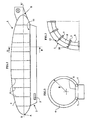
- FIG. 1 represents a dirigible balloon consisting of a basket 2 attached to a ball 1.
- the ball 1 has substantially the shape of a balloon rugby. That is, the shape of the balloon 1 results from the rotation of a curve around the X-X 'axis, the curve intersecting the X-X' axis at two points A and B.
- the airship moves along the horizontal X-X 'axis.
- Basket 2, located under the airship, contains at least the driving unit 5 which drives helium compressors.
- the balloon 1 is composed of a rigid structure on which rests a flexible envelope 3.
- Toros 4 constitute the main elements of the rigid structure.
- Tori 4 are tubes whose axis is substantially a circle of radius R contained in a plane.
- the tori are arranged perpendicular to the axis X-X '.
- the cores 4 are hollow and constitute the helium reservoirs under pressure.
- the tori may be steel tubes whose axis is deformed into circle. According to FIG. 3, tori 4 may also consist of portions of torus 8 assembled together by a small tube or ferrule 9.
- the geometry of a hollow torus is very favorable on the one hand to resist internal pressures and on the other hand to withstand the stresses coming from outside. This means, on the one hand, that a torus-shaped reservoir can contain a large amount of fluid under pressure in relation to its weight and on the other hand a toroidal beam has great rigidity to such as bending, pulling, compressing, twisting in relation to its weight.
- each torus 4 comprises in the lower part a flattening 6.
- the internal volumes of the different tori 4 communicate by tubes 7 whose axes are substantially parallel to the axis X-X '.
- the 7 tubes can be located at the flattening 6 tori 4.
- the tubes 7 may consist of a beam 11, substantially parallel to the axis X-X ', which connects all tori.
- two beams 11 arranged symmetrically with respect to the position of the flattening 6 and the shape of the balloon 1.
- Tubes 7 can make a connection between all volumes internal tori 4 to achieve a single tank.
- the tubes 7 can also realize several tanks each consisting of several cores 4, but each tank being independent of the others.
- Tubes 7 in the form of beams 11 and flattening 6 can serve as a support for hanging basket 2 to the balloon 1.
- the tori 4, their flattening 6 and the tubes 7 are wrapped with a fabric providing waterproofness and thermal insulation.
- the fabric can be a assembly of several layers including a polyethylene layer, a layer reinforced with fibers, such as carbon fibers, and a layer external aluminized.
- the rails 10 can be for example of rectangular section or I-shaped section and be made in aluminum, wood, resin filled with reinforcing fibers.
- the smooth 10 are, in general, perpendicular to the tori so that the whole of the rigid structure consisting of tori 4 and smooth 10 makes a grid of the entire surface of the balloon 1. As shown in FIG. the rails 10 can be fixed on the ferrules 9, or on any other part of the tori 4. The smooth 10 maintain tori relative to each other in a defined position.
- the rigid structure consisting of tori 4 and smooth 10 forms a squared surface on which is deposited the flexible envelope 3.
- the envelope flexible 3 is mainly attached to the rails 10.
- the flexible envelope 3 may contain helium.
- one or more envelopes internal flexible 26, contained in the flexible envelope 3 contain helium.
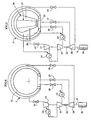
- the internal volume of the envelope 3 communicates by means of a valve 13 with a compressor 14 which discharges the helium at a pressure P1 and a temperature T1 in the heat exchanger 15.
- Fresh air, flowing in the exchanger 15, cools indirectly, ie without contact, helium at a temperature T2.
- helium is compressed at pressure P2 and at a temperature T3 by the compressor 16.
- the helium undergoes cooling in the heat exchanger indirect heat 17 before being introduced into a reservoir 12 consisting of several tori 4 interconnected by tubes 7.
- the heat exchanger 17 also uses the air as a fluid cooling.
- the valve 18 secures the communication between the output of the exchanger 17 and the reservoir 12.
- helium tanks 12 When navigation maneuvers require to increase the quantity of helium in the internal volume of the envelope 3, helium tanks 12 to introduce it into the internal volume of envelope 3.
- the helium contained in the reservoir 12 can be expanded in the turbine 20 before being introduced into the interior volume of the envelope 3.
- the valve 19 controls the opening of the reservoir 12 towards the turbine 20, the valve 21 controls the opening of the casing 3 towards the turbine 20.
- a motor 36 rotates a shaft Y on which are mounted the compressors 14 and 16, and the turbine 20.
- Heat exchangers are essential to perform a polytropic compression of helium. So the performance of the compression will be optimal. On the other hand by limiting the rise of the temperature of helium, organs in contact with helium are preserved from degradation under the effect of a high temperature.
- the operating mode shown in FIG. 5 concerns a balloon airship provided with an envelope 3 which contains one or more envelopes 26 containing helium.
- the shape of the envelope 3 is given by the structure rigid formed including tori 4.
- the shape and volume of the envelope 26, independent of the shape of the envelope 3, is modifiable by a set 27.
- One or more winches 23 make it possible to modify the length of the cables 27.
- the internal volume of the envelope 26 is reduced. Air enters through the heat exchanger heat 15 to fill the space 30 between the envelope 3 and the envelope 26. The weight in the air of the airship increases because of the decrease helium volume.
Landscapes
- Engineering & Computer Science (AREA)
- Mechanical Engineering (AREA)
- Aviation & Aerospace Engineering (AREA)
- Filling Or Discharging Of Gas Storage Vessels (AREA)
- Media Introduction/Drainage Providing Device (AREA)
- Medicines Containing Antibodies Or Antigens For Use As Internal Diagnostic Agents (AREA)
- Materials For Medical Uses (AREA)
- Jet Pumps And Other Pumps (AREA)
- Toys (AREA)
- Organic Insulating Materials (AREA)
- Separation By Low-Temperature Treatments (AREA)
Description
- la figure 1 représente un dispositif à portabilité variable,
- la figure 2 est une vue en coupe selon l'axe X-X' de la figure 1,
- la figure 3 représente en détail une partie de la structure rigide du ballon dirigeable,
- la figure 4 schématise en détail le fonctionnement d'un dispositif à portabilité variable.
Claims (6)
- Dispositif de portabilité variable utilisant un gaz plus léger que l'air, comportant une enveloppe extérieure soutenue par une structure plus rigide, caractérisé en ce que ladite structure comprend une poutre creuse ayant un volume interne servant de réservoir pour stocker ledit gaz.
- Dispositif selon la revendication 1 caractérisé en ce que ladite poutre creuse est recouverte d'un tissu étanche audit gaz et qui isole thermiquement le volume interne de la poutre creuse.
- Dispositif selon l'une des revendications précédentes caractérisé en ce que ladite poutre creuse est un tore creux.
- Dispositif selon la revendication 3 caractérisé en ce que ledit tore creux comprend aux moins deux portions de tores assemblées.
- Dispositif selon la revendication 3 caractérisé en ce que ladite structure comprend au moins deux tores creux dont les volumes internes communiquent.
- Dispositif selon l'une des revendications 3 et 5 caractérisé en ce que ladite structure comprend au moins deux tores creux dont les volumes internes ne communiquent pas.
Applications Claiming Priority (3)
| Application Number | Priority Date | Filing Date | Title |
|---|---|---|---|
| FR0006179A FR2808769B1 (fr) | 2000-05-12 | 2000-05-12 | Ballast pour dirigeable en forme de tore |
| FR0006179 | 2000-05-12 | ||
| PCT/FR2001/001421 WO2001085540A1 (fr) | 2000-05-12 | 2001-05-11 | Ballon dirigeable rigidifie par les reservoirs d'helium |
Publications (3)
| Publication Number | Publication Date |
|---|---|
| EP1280698A1 EP1280698A1 (fr) | 2003-02-05 |
| EP1280698B1 true EP1280698B1 (fr) | 2005-03-30 |
| EP1280698B8 EP1280698B8 (fr) | 2005-06-08 |
Family
ID=8850243
Family Applications (1)
| Application Number | Title | Priority Date | Filing Date |
|---|---|---|---|
| EP01934085A Expired - Lifetime EP1280698B8 (fr) | 2000-05-12 | 2001-05-11 | Ballon dirigeable rigidifie par les reservoirs d'helium |
Country Status (8)
| Country | Link |
|---|---|
| US (1) | US6739549B2 (fr) |
| EP (1) | EP1280698B8 (fr) |
| AT (1) | ATE292043T1 (fr) |
| AU (1) | AU2001260396A1 (fr) |
| CA (1) | CA2408441A1 (fr) |
| DE (1) | DE60109763T2 (fr) |
| FR (1) | FR2808769B1 (fr) |
| WO (1) | WO2001085540A1 (fr) |
Families Citing this family (28)
| Publication number | Priority date | Publication date | Assignee | Title |
|---|---|---|---|---|
| FR2808769B1 (fr) * | 2000-05-12 | 2003-10-17 | Marc Senepart | Ballast pour dirigeable en forme de tore |
| ATE457264T1 (de) * | 2005-06-30 | 2010-02-15 | Kamal Alavi | Unbemanntes luftfahrzeug als plattform für telekommunikative oder für andere wissenschaftliche zwecke |
| US7287723B2 (en) * | 2005-07-14 | 2007-10-30 | Barnes Tracy L | Tethered or free flight blimp with collapsible tail fins |
| CN100422044C (zh) * | 2005-07-28 | 2008-10-01 | 南京大学 | 太阳能可控浮力、自控稳衡氦气蓝天飞船 |
| US7552893B2 (en) * | 2005-09-28 | 2009-06-30 | 21St Century Airship Technologies Inc. | Airship & method of operation |
| US7500637B2 (en) * | 2005-09-30 | 2009-03-10 | Lockheed Martin Corporation | Airship with lifting gas cell system |
| JP2009522170A (ja) * | 2006-01-10 | 2009-06-11 | アラヴィ,カマル | 電気通信又は他の科学目的のための無人航空機 |
| US7500638B2 (en) * | 2006-06-24 | 2009-03-10 | Colvin Jr Charles Roy | Heavy lift airship |
| RU2325303C2 (ru) * | 2006-06-27 | 2008-05-27 | Григорий Геннадьевич Попов | Дирижабль |
| US7487936B2 (en) * | 2006-10-23 | 2009-02-10 | Ltas Holdings, Llc | Buoyancy control system for an airship |
| RU2333133C1 (ru) * | 2007-02-28 | 2008-09-10 | Григорий Геннадьевич Попов | Дирижабль |
| US20080223980A1 (en) * | 2007-03-13 | 2008-09-18 | Dale Po-Kun Fung | Bubble glider |
| US8091826B2 (en) | 2007-04-24 | 2012-01-10 | Michael Todd Voorhees | Aerostatic buoyancy control system |
| DE102008035028A1 (de) | 2008-07-24 | 2010-01-28 | Dmitry Rakov | Vorrichtung zur ballastfreien Flughöhenvariation von Aerostaten |
| US10308340B2 (en) | 2008-10-29 | 2019-06-04 | Rinaldo Brutoco | System, method and apparatus for widespread commercialization of hydrogen as a carbon-free fuel source |
| US9102391B2 (en) | 2008-10-29 | 2015-08-11 | Rinaldo Brutoco | Hydrogen lighter-than-air craft structure |
| US8336810B2 (en) | 2008-10-29 | 2012-12-25 | Rinaldo Brutoco | System, method and apparatus for widespread commercialization of hydrogen as a carbon-free alternative fuel source |
| BE1018347A3 (nl) * | 2008-11-24 | 2010-09-07 | Standaert Lieven | Systeem voor het veilig gebruik van waterstofgas als liftgas in luchtschepen. |
| FR2955558B1 (fr) * | 2010-01-26 | 2015-12-18 | Yves Barbarie | Un aerostat profile pour une meilleure penetration de l'air |
| US8505847B2 (en) * | 2011-03-01 | 2013-08-13 | John Ciampa | Lighter-than-air systems, methods, and kits for obtaining aerial images |
| US9216806B2 (en) * | 2011-11-23 | 2015-12-22 | Stratospheric Airships, Llc | Durable airship hull and in situ airship hull repair |
| RU2507111C2 (ru) * | 2012-02-16 | 2014-02-20 | Евгений Фёдорович Белышев | Дирижабль многоцелевой |
| RU2550926C1 (ru) * | 2013-12-12 | 2015-05-20 | Юлия Алексеевна Щепочкина | Носовая часть летательного аппарата |
| WO2015102425A1 (fr) * | 2014-01-04 | 2015-07-09 | 이정용 | Appareil ayant une direction commandée par la flottabilité |
| US20170096208A1 (en) * | 2015-10-06 | 2017-04-06 | Jeff Klagenberg | Multi-Layer Fluid Containment Recovery System |
| EP3241738A1 (fr) * | 2016-05-06 | 2017-11-08 | Wanlu Wu | Un dirigeable |
| CN108482632A (zh) * | 2018-03-12 | 2018-09-04 | 山东东晟飞艇科技有限公司 | 一种硬式飞艇 |
| US10589969B2 (en) | 2018-04-25 | 2020-03-17 | Rinaldo Brutoco | System, method and apparatus for widespread commercialization of hydrogen as a carbon-free alternative fuel source |
Family Cites Families (10)
| Publication number | Priority date | Publication date | Assignee | Title |
|---|---|---|---|---|
| FR407385A (fr) * | 1908-10-03 | 1910-02-26 | Adrien Baumann | Ballon dirigeable, démontable, rigide |
| GB237346A (en) * | 1924-04-24 | 1925-07-24 | Humphrey Francis Parker | Improvements in airships |
| US1900743A (en) * | 1929-03-18 | 1933-03-07 | Zeppelin Luftschiffbau | Airship |
| US3032298A (en) * | 1959-10-29 | 1962-05-01 | Francis P Callahan | Airplane fuselage construction with helium lift |
| US3443776A (en) * | 1966-05-04 | 1969-05-13 | Alvin E Moore | Ringplane |
| US3559920A (en) * | 1967-08-22 | 1971-02-02 | Moore Alvin E | Crashproof light-weight vehicle |
| US4052025A (en) * | 1975-04-03 | 1977-10-04 | Clark Frank M | Semi-buoyant aircraft |
| FR2320229A1 (fr) * | 1975-08-04 | 1977-03-04 | Zodiac | Perfectionnements apportes aux aerostats, notamment aux dirigeables, et a leur procede de mise en oeuvre |
| US5005783A (en) * | 1990-01-18 | 1991-04-09 | The United States Of America As Represented By The Secretary Of The Air Force | Variable geometry airship |
| FR2808769B1 (fr) * | 2000-05-12 | 2003-10-17 | Marc Senepart | Ballast pour dirigeable en forme de tore |
-
2000
- 2000-05-12 FR FR0006179A patent/FR2808769B1/fr not_active Expired - Fee Related
-
2001
- 2001-05-11 CA CA002408441A patent/CA2408441A1/fr not_active Abandoned
- 2001-05-11 AT AT01934085T patent/ATE292043T1/de not_active IP Right Cessation
- 2001-05-11 EP EP01934085A patent/EP1280698B8/fr not_active Expired - Lifetime
- 2001-05-11 DE DE60109763T patent/DE60109763T2/de not_active Expired - Fee Related
- 2001-05-11 WO PCT/FR2001/001421 patent/WO2001085540A1/fr not_active Ceased
- 2001-05-11 AU AU2001260396A patent/AU2001260396A1/en not_active Abandoned
- 2001-05-11 US US10/276,021 patent/US6739549B2/en not_active Expired - Fee Related
Also Published As
| Publication number | Publication date |
|---|---|
| CA2408441A1 (fr) | 2001-11-15 |
| DE60109763T2 (de) | 2006-03-30 |
| FR2808769B1 (fr) | 2003-10-17 |
| DE60109763D1 (de) | 2005-05-04 |
| EP1280698B8 (fr) | 2005-06-08 |
| AU2001260396A1 (en) | 2001-11-20 |
| WO2001085540A1 (fr) | 2001-11-15 |
| ATE292043T1 (de) | 2005-04-15 |
| EP1280698A1 (fr) | 2003-02-05 |
| FR2808769A1 (fr) | 2001-11-16 |
| US6739549B2 (en) | 2004-05-25 |
| US20030141410A1 (en) | 2003-07-31 |
Similar Documents
| Publication | Publication Date | Title |
|---|---|---|
| EP1280698A1 (fr) | Ballon dirigeable rigidifie par les reservoirs d'helium | |
| EP1294608B1 (fr) | Ballon dirigeable a portance variable | |
| US6868981B2 (en) | Light weight hydrogen tank | |
| FR2662490A1 (fr) | Ensemble d'isolation thermique. | |
| EP4010644B1 (fr) | Dispositif et installation de réfrigération | |
| EP4129828B1 (fr) | Aéronef comprenant un dispositif d alimentation en hydrogène intégrant un système de chauffage de l hydrogène positionné dans le fuselage de l aéronef | |
| FR3014417A1 (fr) | Nouvelle architecture de vehicule spatial | |
| EP3488139B1 (fr) | Module et systeme de depressurisation d'un reservoir cryogenique. | |
| EP4435258B1 (fr) | Dispositif et procédé de compression | |
| CA2531000A1 (fr) | Reservoir de fluide cryogenique et utilisation dans un vehicule automobile | |
| EP3587767A1 (fr) | Structure d'entree d'air pour une nacelle d'aeronef comportant un element amortisseur de chocs | |
| WO2008059144B1 (fr) | Dispositif sécurisé de transport et de stockage d'hydrogène | |
| FR2587444A1 (fr) | Ligne de transfert de gaz liquefie comportant un ecran thermique muni d'un echangeur | |
| EP0421887B1 (fr) | Ecran d'isolation acoustique pour protéger le compartiment pour charge utile d'un lanceur. | |
| CN119178103B (zh) | 一种便携式快速充氧氮气设备 | |
| EP4170222B1 (fr) | Réservoir cryogénique de stockage de gaz liquéfié | |
| FR3080361A1 (fr) | Aerostat presentant un ballon a double enveloppe | |
| WO2023175260A1 (fr) | Dispositif de reservoir cryogenique aeronautique de stockage d'hydrogene, pour emport exterieur par un aeronef | |
| WO2023118374A1 (fr) | Unité de stockage de fluide cryogénique | |
| FR3130934A1 (fr) | Ensemble de stockage de fluide cryogénique | |
| FR3138649A1 (fr) | Aerostat dirigeable a enveloppe hybride | |
| FR3140417A1 (fr) | Dispositif de réfrigération à basse température | |
| BE545575A (fr) | ||
| FR2550096A1 (fr) | Dispositif de conservation et de regeneration d'objets pressurises | |
| FR2544900A1 (fr) | Procede et dispositif d'isolation acoustique d'une source de bruit |
Legal Events
| Date | Code | Title | Description |
|---|---|---|---|
| PUAI | Public reference made under article 153(3) epc to a published international application that has entered the european phase |
Free format text: ORIGINAL CODE: 0009012 |
|
| AK | Designated contracting states |
Designated state(s): AT BE CH CY DE DK ES FI FR GB GR IE IT LI LU MC NL PT SE TR |
|
| AX | Request for extension of the european patent |
Extension state: AL LT LV MK RO SI |
|
| 17P | Request for examination filed |
Effective date: 20021121 |
|
| RAP1 | Party data changed (applicant data changed or rights of an application transferred) |
Owner name: AEROSPACE ADOUR TECHNOLOGY Owner name: SENEPART, MARC |
|
| GRAP | Despatch of communication of intention to grant a patent |
Free format text: ORIGINAL CODE: EPIDOSNIGR1 |
|
| GRAS | Grant fee paid |
Free format text: ORIGINAL CODE: EPIDOSNIGR3 |
|
| GRAA | (expected) grant |
Free format text: ORIGINAL CODE: 0009210 |
|
| AK | Designated contracting states |
Kind code of ref document: B1 Designated state(s): AT BE CH CY DE DK ES FI FR GB GR IE IT LI LU MC NL PT SE TR |
|
| PG25 | Lapsed in a contracting state [announced via postgrant information from national office to epo] |
Ref country code: IT Free format text: LAPSE BECAUSE OF FAILURE TO SUBMIT A TRANSLATION OF THE DESCRIPTION OR TO PAY THE FEE WITHIN THE PRESCRIBED TIME-LIMIT;WARNING: LAPSES OF ITALIAN PATENTS WITH EFFECTIVE DATE BEFORE 2007 MAY HAVE OCCURRED AT ANY TIME BEFORE 2007. THE CORRECT EFFECTIVE DATE MAY BE DIFFERENT FROM THE ONE RECORDED. Effective date: 20050330 Ref country code: NL Free format text: LAPSE BECAUSE OF FAILURE TO SUBMIT A TRANSLATION OF THE DESCRIPTION OR TO PAY THE FEE WITHIN THE PRESCRIBED TIME-LIMIT Effective date: 20050330 Ref country code: FI Free format text: LAPSE BECAUSE OF FAILURE TO SUBMIT A TRANSLATION OF THE DESCRIPTION OR TO PAY THE FEE WITHIN THE PRESCRIBED TIME-LIMIT Effective date: 20050330 Ref country code: ES Free format text: LAPSE BECAUSE OF FAILURE TO SUBMIT A TRANSLATION OF THE DESCRIPTION OR TO PAY THE FEE WITHIN THE PRESCRIBED TIME-LIMIT Effective date: 20050330 Ref country code: AT Free format text: LAPSE BECAUSE OF FAILURE TO SUBMIT A TRANSLATION OF THE DESCRIPTION OR TO PAY THE FEE WITHIN THE PRESCRIBED TIME-LIMIT Effective date: 20050330 Ref country code: IE Free format text: LAPSE BECAUSE OF FAILURE TO SUBMIT A TRANSLATION OF THE DESCRIPTION OR TO PAY THE FEE WITHIN THE PRESCRIBED TIME-LIMIT Effective date: 20050330 Ref country code: TR Free format text: LAPSE BECAUSE OF FAILURE TO SUBMIT A TRANSLATION OF THE DESCRIPTION OR TO PAY THE FEE WITHIN THE PRESCRIBED TIME-LIMIT Effective date: 20050330 |
|
| REG | Reference to a national code |
Ref country code: GB Ref legal event code: FG4D Free format text: NOT ENGLISH |
|
| REG | Reference to a national code |
Ref country code: CH Ref legal event code: EP |
|
| REF | Corresponds to: |
Ref document number: 60109763 Country of ref document: DE Date of ref document: 20050504 Kind code of ref document: P |
|
| REG | Reference to a national code |
Ref country code: IE Ref legal event code: FG4D Free format text: LANGUAGE OF EP DOCUMENT: FRENCH |
|
| PG25 | Lapsed in a contracting state [announced via postgrant information from national office to epo] |
Ref country code: CY Free format text: LAPSE BECAUSE OF FAILURE TO SUBMIT A TRANSLATION OF THE DESCRIPTION OR TO PAY THE FEE WITHIN THE PRESCRIBED TIME-LIMIT Effective date: 20050511 Ref country code: LU Free format text: LAPSE BECAUSE OF NON-PAYMENT OF DUE FEES Effective date: 20050511 |
|
| RAP2 | Party data changed (patent owner data changed or rights of a patent transferred) |
Owner name: AEROSPACE ADOUR TECHNOLOGY |
|
| RIN2 | Information on inventor provided after grant (corrected) |
Inventor name: SENEPART, MARC |
|
| PG25 | Lapsed in a contracting state [announced via postgrant information from national office to epo] |
Ref country code: MC Free format text: LAPSE BECAUSE OF NON-PAYMENT OF DUE FEES Effective date: 20050531 Ref country code: CH Free format text: LAPSE BECAUSE OF NON-PAYMENT OF DUE FEES Effective date: 20050531 Ref country code: LI Free format text: LAPSE BECAUSE OF NON-PAYMENT OF DUE FEES Effective date: 20050531 Ref country code: BE Free format text: LAPSE BECAUSE OF NON-PAYMENT OF DUE FEES Effective date: 20050531 |
|
| PGFP | Annual fee paid to national office [announced via postgrant information from national office to epo] |
Ref country code: DE Payment date: 20050623 Year of fee payment: 5 |
|
| PGFP | Annual fee paid to national office [announced via postgrant information from national office to epo] |
Ref country code: GB Payment date: 20050624 Year of fee payment: 5 |
|
| PG25 | Lapsed in a contracting state [announced via postgrant information from national office to epo] |
Ref country code: DK Free format text: LAPSE BECAUSE OF FAILURE TO SUBMIT A TRANSLATION OF THE DESCRIPTION OR TO PAY THE FEE WITHIN THE PRESCRIBED TIME-LIMIT Effective date: 20050630 Ref country code: GR Free format text: LAPSE BECAUSE OF FAILURE TO SUBMIT A TRANSLATION OF THE DESCRIPTION OR TO PAY THE FEE WITHIN THE PRESCRIBED TIME-LIMIT Effective date: 20050630 |
|
| NLT2 | Nl: modifications (of names), taken from the european patent patent bulletin |
Owner name: AEROSPACE ADOUR TECHNOLOGY |
|
| GBT | Gb: translation of ep patent filed (gb section 77(6)(a)/1977) |
Effective date: 20050725 |
|
| PG25 | Lapsed in a contracting state [announced via postgrant information from national office to epo] |
Ref country code: PT Free format text: LAPSE BECAUSE OF FAILURE TO SUBMIT A TRANSLATION OF THE DESCRIPTION OR TO PAY THE FEE WITHIN THE PRESCRIBED TIME-LIMIT Effective date: 20050908 |
|
| NLV1 | Nl: lapsed or annulled due to failure to fulfill the requirements of art. 29p and 29m of the patents act | ||
| BERE | Be: lapsed |
Owner name: AEROSPACE ADOUR TECHNOLOGY Effective date: 20050531 Owner name: SENEPART, MARC Effective date: 20050531 |
|
| REG | Reference to a national code |
Ref country code: IE Ref legal event code: FD4D |
|
| REG | Reference to a national code |
Ref country code: CH Ref legal event code: PL |
|
| PLBE | No opposition filed within time limit |
Free format text: ORIGINAL CODE: 0009261 |
|
| STAA | Information on the status of an ep patent application or granted ep patent |
Free format text: STATUS: NO OPPOSITION FILED WITHIN TIME LIMIT |
|
| 26N | No opposition filed |
Effective date: 20060102 |
|
| PG25 | Lapsed in a contracting state [announced via postgrant information from national office to epo] |
Ref country code: GB Free format text: LAPSE BECAUSE OF NON-PAYMENT OF DUE FEES Effective date: 20060511 |
|
| PG25 | Lapsed in a contracting state [announced via postgrant information from national office to epo] |
Ref country code: DE Free format text: LAPSE BECAUSE OF NON-PAYMENT OF DUE FEES Effective date: 20061201 |
|
| GBPC | Gb: european patent ceased through non-payment of renewal fee |
Effective date: 20060511 |
|
| BERE | Be: lapsed |
Owner name: SENEPART, MARC Effective date: 20050531 Owner name: AEROSPACE ADOUR TECHNOLOGY Effective date: 20050531 |
|
| PG25 | Lapsed in a contracting state [announced via postgrant information from national office to epo] |
Ref country code: SE Free format text: LAPSE BECAUSE OF FAILURE TO SUBMIT A TRANSLATION OF THE DESCRIPTION OR TO PAY THE FEE WITHIN THE PRESCRIBED TIME-LIMIT Effective date: 20050630 |
|
| REG | Reference to a national code |
Ref country code: FR Ref legal event code: PLFP Year of fee payment: 15 |
|
| REG | Reference to a national code |
Ref country code: FR Ref legal event code: PLFP Year of fee payment: 16 |
|
| PGFP | Annual fee paid to national office [announced via postgrant information from national office to epo] |
Ref country code: FR Payment date: 20160601 Year of fee payment: 16 |
|
| REG | Reference to a national code |
Ref country code: FR Ref legal event code: ST Effective date: 20180131 |
|
| PG25 | Lapsed in a contracting state [announced via postgrant information from national office to epo] |
Ref country code: FR Free format text: LAPSE BECAUSE OF NON-PAYMENT OF DUE FEES Effective date: 20170531 |