EP1281073B1 - Separation de composes par electrophorese - Google Patents
Separation de composes par electrophorese Download PDFInfo
- Publication number
- EP1281073B1 EP1281073B1 EP01945155A EP01945155A EP1281073B1 EP 1281073 B1 EP1281073 B1 EP 1281073B1 EP 01945155 A EP01945155 A EP 01945155A EP 01945155 A EP01945155 A EP 01945155A EP 1281073 B1 EP1281073 B1 EP 1281073B1
- Authority
- EP
- European Patent Office
- Prior art keywords
- compounds
- solution
- buffering system
- chemical buffering
- analyte solution
- Prior art date
- Legal status (The legal status is an assumption and is not a legal conclusion. Google has not performed a legal analysis and makes no representation as to the accuracy of the status listed.)
- Expired - Lifetime
Links
- 150000001875 compounds Chemical class 0.000 title claims description 117
- 230000003139 buffering effect Effects 0.000 claims description 101
- 239000012491 analyte Substances 0.000 claims description 100
- 239000000126 substance Substances 0.000 claims description 99
- 238000000926 separation method Methods 0.000 claims description 84
- 238000000746 purification Methods 0.000 claims description 82
- 102000004169 proteins and genes Human genes 0.000 claims description 78
- 108090000623 proteins and genes Proteins 0.000 claims description 78
- 238000000034 method Methods 0.000 claims description 42
- 230000007935 neutral effect Effects 0.000 claims description 28
- 150000001793 charged compounds Chemical class 0.000 claims description 24
- 230000005684 electric field Effects 0.000 claims description 20
- 239000012528 membrane Substances 0.000 claims description 19
- 238000001514 detection method Methods 0.000 claims description 14
- 108010029485 Protein Isoforms Proteins 0.000 claims description 11
- 102000001708 Protein Isoforms Human genes 0.000 claims description 11
- 239000011159 matrix material Substances 0.000 claims description 7
- 238000000605 extraction Methods 0.000 claims description 6
- 239000012530 fluid Substances 0.000 claims description 5
- 230000015572 biosynthetic process Effects 0.000 claims description 4
- 230000008878 coupling Effects 0.000 claims description 4
- 238000010168 coupling process Methods 0.000 claims description 4
- 238000005859 coupling reaction Methods 0.000 claims description 4
- 238000011033 desalting Methods 0.000 claims description 3
- 239000011521 glass Substances 0.000 claims description 3
- 230000031700 light absorption Effects 0.000 claims description 3
- 229920000642 polymer Polymers 0.000 claims description 3
- 238000001179 sorption measurement Methods 0.000 claims description 3
- 238000006911 enzymatic reaction Methods 0.000 claims description 2
- 238000004519 manufacturing process Methods 0.000 claims description 2
- 150000002894 organic compounds Chemical class 0.000 claims description 2
- -1 organic compounds Chemical class 0.000 claims description 2
- 238000011002 quantification Methods 0.000 claims 2
- 238000006243 chemical reaction Methods 0.000 claims 1
- 239000003795 chemical substances by application Substances 0.000 claims 1
- 239000003960 organic solvent Substances 0.000 claims 1
- 239000000243 solution Substances 0.000 description 173
- 239000000499 gel Substances 0.000 description 89
- 235000018102 proteins Nutrition 0.000 description 76
- 238000004458 analytical method Methods 0.000 description 29
- 238000002474 experimental method Methods 0.000 description 29
- 238000013508 migration Methods 0.000 description 26
- 230000005012 migration Effects 0.000 description 26
- 239000000203 mixture Substances 0.000 description 18
- CXKWCBBOMKCUKX-UHFFFAOYSA-M methylene blue Chemical compound [Cl-].C1=CC(N(C)C)=CC2=[S+]C3=CC(N(C)C)=CC=C3N=C21 CXKWCBBOMKCUKX-UHFFFAOYSA-M 0.000 description 17
- 229960000907 methylthioninium chloride Drugs 0.000 description 17
- 239000000872 buffer Substances 0.000 description 16
- 238000001155 isoelectric focusing Methods 0.000 description 16
- XLYOFNOQVPJJNP-UHFFFAOYSA-N water Substances O XLYOFNOQVPJJNP-UHFFFAOYSA-N 0.000 description 15
- 238000000533 capillary isoelectric focusing Methods 0.000 description 11
- 238000001962 electrophoresis Methods 0.000 description 10
- BASFCYQUMIYNBI-UHFFFAOYSA-N platinum Chemical compound [Pt] BASFCYQUMIYNBI-UHFFFAOYSA-N 0.000 description 10
- 239000000523 sample Substances 0.000 description 10
- 238000004088 simulation Methods 0.000 description 9
- 230000008901 benefit Effects 0.000 description 8
- 238000011084 recovery Methods 0.000 description 8
- 241000283073 Equus caballus Species 0.000 description 7
- BELBBZDIHDAJOR-UHFFFAOYSA-N Phenolsulfonephthalein Chemical compound C1=CC(O)=CC=C1C1(C=2C=CC(O)=CC=2)C2=CC=CC=C2S(=O)(=O)O1 BELBBZDIHDAJOR-UHFFFAOYSA-N 0.000 description 7
- 238000009826 distribution Methods 0.000 description 7
- 238000004949 mass spectrometry Methods 0.000 description 7
- 229960003531 phenolsulfonphthalein Drugs 0.000 description 7
- 229920003023 plastic Polymers 0.000 description 7
- 239000004033 plastic Substances 0.000 description 7
- 102100030497 Cytochrome c Human genes 0.000 description 6
- 108010075031 Cytochromes c Proteins 0.000 description 6
- 108010053210 Phycocyanin Proteins 0.000 description 6
- 239000002253 acid Substances 0.000 description 6
- 239000000463 material Substances 0.000 description 6
- 108090000765 processed proteins & peptides Proteins 0.000 description 6
- 102100030856 Myoglobin Human genes 0.000 description 5
- 108010062374 Myoglobin Proteins 0.000 description 5
- 101710162629 Trypsin inhibitor Proteins 0.000 description 5
- 238000001502 gel electrophoresis Methods 0.000 description 5
- 150000002500 ions Chemical class 0.000 description 5
- 229910052697 platinum Inorganic materials 0.000 description 5
- 238000004064 recycling Methods 0.000 description 5
- 230000003068 static effect Effects 0.000 description 5
- 108010012717 N-acetyleglin c Proteins 0.000 description 4
- 229920005372 Plexiglas® Polymers 0.000 description 4
- 229940122618 Trypsin inhibitor Drugs 0.000 description 4
- 239000000959 ampholyte mixture Substances 0.000 description 4
- 230000000694 effects Effects 0.000 description 4
- 238000002347 injection Methods 0.000 description 4
- 239000007924 injection Substances 0.000 description 4
- 239000003550 marker Substances 0.000 description 4
- 230000002572 peristaltic effect Effects 0.000 description 4
- 239000012460 protein solution Substances 0.000 description 4
- 150000003839 salts Chemical class 0.000 description 4
- 239000002753 trypsin inhibitor Substances 0.000 description 4
- 239000013598 vector Substances 0.000 description 4
- 108010088751 Albumins Proteins 0.000 description 3
- 102000009027 Albumins Human genes 0.000 description 3
- 108010026552 Proteome Proteins 0.000 description 3
- 239000012472 biological sample Substances 0.000 description 3
- 239000008366 buffered solution Substances 0.000 description 3
- 239000011544 gradient gel Substances 0.000 description 3
- 238000001819 mass spectrum Methods 0.000 description 3
- 230000035515 penetration Effects 0.000 description 3
- 239000007787 solid Substances 0.000 description 3
- IJGRMHOSHXDMSA-UHFFFAOYSA-N Atomic nitrogen Chemical compound N#N IJGRMHOSHXDMSA-UHFFFAOYSA-N 0.000 description 2
- 108090000790 Enzymes Proteins 0.000 description 2
- 102000004190 Enzymes Human genes 0.000 description 2
- 102000008192 Lactoglobulins Human genes 0.000 description 2
- 108010060630 Lactoglobulins Proteins 0.000 description 2
- VVQNEPGJFQJSBK-UHFFFAOYSA-N Methyl methacrylate Chemical compound COC(=O)C(C)=C VVQNEPGJFQJSBK-UHFFFAOYSA-N 0.000 description 2
- 150000007513 acids Chemical class 0.000 description 2
- 238000013459 approach Methods 0.000 description 2
- 238000000065 atmospheric pressure chemical ionisation Methods 0.000 description 2
- 239000002585 base Substances 0.000 description 2
- 239000007853 buffer solution Substances 0.000 description 2
- 238000004364 calculation method Methods 0.000 description 2
- 235000014633 carbohydrates Nutrition 0.000 description 2
- 150000001720 carbohydrates Chemical class 0.000 description 2
- 150000001768 cations Chemical class 0.000 description 2
- 230000001413 cellular effect Effects 0.000 description 2
- 239000003153 chemical reaction reagent Substances 0.000 description 2
- 238000005094 computer simulation Methods 0.000 description 2
- 238000001816 cooling Methods 0.000 description 2
- 230000003247 decreasing effect Effects 0.000 description 2
- 239000000284 extract Substances 0.000 description 2
- 230000004907 flux Effects 0.000 description 2
- 238000001997 free-flow electrophoresis Methods 0.000 description 2
- 239000007789 gas Substances 0.000 description 2
- 239000012535 impurity Substances 0.000 description 2
- 150000002632 lipids Chemical class 0.000 description 2
- 238000000816 matrix-assisted laser desorption--ionisation Methods 0.000 description 2
- 238000012986 modification Methods 0.000 description 2
- 230000004048 modification Effects 0.000 description 2
- 108020004707 nucleic acids Proteins 0.000 description 2
- 102000039446 nucleic acids Human genes 0.000 description 2
- 150000007523 nucleic acids Chemical class 0.000 description 2
- 229920002401 polyacrylamide Polymers 0.000 description 2
- 239000004926 polymethyl methacrylate Substances 0.000 description 2
- 238000001556 precipitation Methods 0.000 description 2
- 239000000047 product Substances 0.000 description 2
- 238000005086 pumping Methods 0.000 description 2
- 241000894007 species Species 0.000 description 2
- 101000946377 Bos taurus Alpha-lactalbumin Proteins 0.000 description 1
- 108091003079 Bovine Serum Albumin Proteins 0.000 description 1
- 102000003886 Glycoproteins Human genes 0.000 description 1
- 108090000288 Glycoproteins Proteins 0.000 description 1
- 235000000177 Indigofera tinctoria Nutrition 0.000 description 1
- 102000004407 Lactalbumin Human genes 0.000 description 1
- 108020004511 Recombinant DNA Proteins 0.000 description 1
- XUIMIQQOPSSXEZ-UHFFFAOYSA-N Silicon Chemical compound [Si] XUIMIQQOPSSXEZ-UHFFFAOYSA-N 0.000 description 1
- 239000004809 Teflon Substances 0.000 description 1
- 229920006362 Teflon® Polymers 0.000 description 1
- 235000010724 Wisteria floribunda Nutrition 0.000 description 1
- 238000010521 absorption reaction Methods 0.000 description 1
- 239000008351 acetate buffer Substances 0.000 description 1
- 230000002378 acidificating effect Effects 0.000 description 1
- 150000003926 acrylamides Chemical class 0.000 description 1
- 238000013019 agitation Methods 0.000 description 1
- WYTGDNHDOZPMIW-RCBQFDQVSA-N alstonine Natural products C1=CC2=C3C=CC=CC3=NC2=C2N1C[C@H]1[C@H](C)OC=C(C(=O)OC)[C@H]1C2 WYTGDNHDOZPMIW-RCBQFDQVSA-N 0.000 description 1
- 150000001413 amino acids Chemical class 0.000 description 1
- 125000000129 anionic group Chemical group 0.000 description 1
- 230000004071 biological effect Effects 0.000 description 1
- 229940098773 bovine serum albumin Drugs 0.000 description 1
- 239000006227 byproduct Substances 0.000 description 1
- 238000004422 calculation algorithm Methods 0.000 description 1
- 210000004027 cell Anatomy 0.000 description 1
- 238000004587 chromatography analysis Methods 0.000 description 1
- ONCCWDRMOZMNSM-FBCQKBJTSA-N compound Z Chemical compound N1=C2C(=O)NC(N)=NC2=NC=C1C(=O)[C@H]1OP(O)(=O)OC[C@H]1O ONCCWDRMOZMNSM-FBCQKBJTSA-N 0.000 description 1
- 229920001940 conductive polymer Polymers 0.000 description 1
- 238000010276 construction Methods 0.000 description 1
- 238000005520 cutting process Methods 0.000 description 1
- 230000006378 damage Effects 0.000 description 1
- 230000007423 decrease Effects 0.000 description 1
- 238000003795 desorption Methods 0.000 description 1
- 238000011161 development Methods 0.000 description 1
- 238000010586 diagram Methods 0.000 description 1
- 238000000502 dialysis Methods 0.000 description 1
- 238000009792 diffusion process Methods 0.000 description 1
- 238000010790 dilution Methods 0.000 description 1
- 239000012895 dilution Substances 0.000 description 1
- 238000011143 downstream manufacturing Methods 0.000 description 1
- 238000005370 electroosmosis Methods 0.000 description 1
- 230000008030 elimination Effects 0.000 description 1
- 238000003379 elimination reaction Methods 0.000 description 1
- 238000005516 engineering process Methods 0.000 description 1
- 210000003918 fraction a Anatomy 0.000 description 1
- 238000005194 fractionation Methods 0.000 description 1
- 230000005484 gravity Effects 0.000 description 1
- 229940097275 indigo Drugs 0.000 description 1
- COHYTHOBJLSHDF-UHFFFAOYSA-N indigo powder Natural products N1C2=CC=CC=C2C(=O)C1=C1C(=O)C2=CC=CC=C2N1 COHYTHOBJLSHDF-UHFFFAOYSA-N 0.000 description 1
- 229910052500 inorganic mineral Inorganic materials 0.000 description 1
- 239000011810 insulating material Substances 0.000 description 1
- 230000010354 integration Effects 0.000 description 1
- 238000002955 isolation Methods 0.000 description 1
- 239000007788 liquid Substances 0.000 description 1
- 238000011068 loading method Methods 0.000 description 1
- 230000007246 mechanism Effects 0.000 description 1
- 239000011707 mineral Substances 0.000 description 1
- 229910052757 nitrogen Inorganic materials 0.000 description 1
- 230000003287 optical effect Effects 0.000 description 1
- 239000007800 oxidant agent Substances 0.000 description 1
- 230000037361 pathway Effects 0.000 description 1
- 238000011020 pilot scale process Methods 0.000 description 1
- 238000002264 polyacrylamide gel electrophoresis Methods 0.000 description 1
- 102000004196 processed proteins & peptides Human genes 0.000 description 1
- 239000012474 protein marker Substances 0.000 description 1
- 238000001742 protein purification Methods 0.000 description 1
- 230000003134 recirculating effect Effects 0.000 description 1
- 238000011160 research Methods 0.000 description 1
- 239000012146 running buffer Substances 0.000 description 1
- 239000012488 sample solution Substances 0.000 description 1
- 238000005070 sampling Methods 0.000 description 1
- 238000012216 screening Methods 0.000 description 1
- 229910052710 silicon Inorganic materials 0.000 description 1
- 239000010703 silicon Substances 0.000 description 1
- 239000002904 solvent Substances 0.000 description 1
- 238000001228 spectrum Methods 0.000 description 1
- 238000002335 split flow thin fractionation Methods 0.000 description 1
- 239000000758 substrate Substances 0.000 description 1
- 238000012360 testing method Methods 0.000 description 1
- 229920005992 thermoplastic resin Polymers 0.000 description 1
- 150000004886 thiomorpholines Chemical class 0.000 description 1
- 239000006200 vaporizer Substances 0.000 description 1
- 230000004304 visual acuity Effects 0.000 description 1
- 239000002699 waste material Substances 0.000 description 1
- 235000021241 α-lactalbumin Nutrition 0.000 description 1
Images


Classifications
-
- G—PHYSICS
- G01—MEASURING; TESTING
- G01N—INVESTIGATING OR ANALYSING MATERIALS BY DETERMINING THEIR CHEMICAL OR PHYSICAL PROPERTIES
- G01N27/00—Investigating or analysing materials by the use of electric, electrochemical, or magnetic means
- G01N27/26—Investigating or analysing materials by the use of electric, electrochemical, or magnetic means by investigating electrochemical variables; by using electrolysis or electrophoresis
- G01N27/416—Systems
- G01N27/447—Systems using electrophoresis
- G01N27/44756—Apparatus specially adapted therefor
- G01N27/44795—Isoelectric focusing
-
- G—PHYSICS
- G01—MEASURING; TESTING
- G01N—INVESTIGATING OR ANALYSING MATERIALS BY DETERMINING THEIR CHEMICAL OR PHYSICAL PROPERTIES
- G01N27/00—Investigating or analysing materials by the use of electric, electrochemical, or magnetic means
- G01N27/26—Investigating or analysing materials by the use of electric, electrochemical, or magnetic means by investigating electrochemical variables; by using electrolysis or electrophoresis
- G01N27/416—Systems
- G01N27/447—Systems using electrophoresis
- G01N27/44756—Apparatus specially adapted therefor
- G01N27/44769—Continuous electrophoresis, i.e. the sample being continuously introduced, e.g. free flow electrophoresis [FFE]
-
- G—PHYSICS
- G01—MEASURING; TESTING
- G01N—INVESTIGATING OR ANALYSING MATERIALS BY DETERMINING THEIR CHEMICAL OR PHYSICAL PROPERTIES
- G01N30/00—Investigating or analysing materials by separation into components using adsorption, absorption or similar phenomena or using ion-exchange, e.g. chromatography or field flow fractionation
- G01N30/0005—Field flow fractionation
- G01N2030/0015—Field flow fractionation characterised by driving force
- G01N2030/0035—Field flow fractionation characterised by driving force electrical field
-
- G—PHYSICS
- G01—MEASURING; TESTING
- G01N—INVESTIGATING OR ANALYSING MATERIALS BY DETERMINING THEIR CHEMICAL OR PHYSICAL PROPERTIES
- G01N30/00—Investigating or analysing materials by separation into components using adsorption, absorption or similar phenomena or using ion-exchange, e.g. chromatography or field flow fractionation
- G01N30/02—Column chromatography
- G01N30/26—Conditioning of the fluid carrier; Flow patterns
- G01N30/28—Control of physical parameters of the fluid carrier
- G01N2030/285—Control of physical parameters of the fluid carrier electrically driven carrier
Definitions
- This invention relates to the electrophoretic separation, purification and recovery of compounds from solution.
- Complex mixtures such as biological samples can contain up to 30,000 different proteins which need to be separated and identified for further analysis.
- proteome analysis high resolution separation of complex protein mixtures requires the development of novel techniques which minimize separation times, are easy to use, result in a high degree of purity and allow for further analysis of the compound(s) of interest extracted from the sample without unnecessary additional purification steps.
- 2D-gel electrophoresis is one technique which is capable of separating such complex biological samples (Wilkins,M.R. et al., Proteome Research: New Frontiers in Functional Genomics; Springer, 1997).
- proteins are separated first by an isoelectric focusing (IEF) step according to their isoelectric point.
- IEF isoelectric focusing
- proteins are separated as a function of their molecular mass by a polyacrylamide gel electrophoresis (PAGE) step.
- PAGE polyacrylamide gel electrophoresis
- the result is a two-dimensional image in which each visible spot corresponds to a specific protein. If further analysis of a protein is required, for example, analysis of peptide composition or biological activity, then the protein has to be first extracted from the gel matrix before it can be analysed with the appropriate method to obtain the desired information.
- MS mass spectroscopy
- Another way of avoiding undesired compounds in the sample is to use a direct laser desorption technique from the 2D-gel (Ogorzalek Loo R.R., et al., Analytical Chemistry, 1996, 68, 1910-1917) or an electroblotted 2D-gel (Eckerskorn,C. et.al., Analytical Chemistry, 1997, 69, 2888-2892; Strupat,K. et al. Analytical Chemistry, 1994, 66, 464-470). All of these additional purification steps complicate the analysis procedure and are time-consuming.
- IEF iso-electric focusing
- SPLITT isoelectric split-flow thin
- a modification of this approach is the tangential electrophoretic apparatus from Bier, (US 5540826).
- the different compartments are arranged in such a manner that an array of multi-channels is separated from a second array of multi-channels slightly displaced through a single screen.
- An electrical field is applied perpendicularly to the channels which enables an electrophoretic serpentine pathway through the channels.
- the pH in the channels is fixed by ampholytes and recycling is possible with independent inlet and outlet ports at every channel.
- the major disadvantages of this system are that the device has a complicated construction of multi-channels through which the solution must flow and that the compound(s) of interest remain(s) in an ampholyte solution which needs to be removed before further analysis of the desired compound or compounds is possible.
- the analyte is mixed with a running buffer and several strategies of fluid handling are presented to either fractionate or desalt the sample or to work in a non convective and/or low water diffusion medium. All these isoelectric focusing devices have a major disadvantage in terms of further analysis of compounds. They all contain in the final separated fraction a certain amount of undesired buffering species or ampholytes.
- the device is composed of multiple compartments sandwiched between an anodic and a cathodic reservoir separated by immobiline isoelectric membranes, allowing the recovery of proteins in an ampholyte-free solution.
- This device can be composed of several compartments separated by immobiline gels stabilised by membranes.
- the separation of fractions is achieved in such a way that the protein stops migrating in an electrical field in between two immobiline membranes, wherein one membrane establishes a pH higher than the protein's pI and the other a pH lower than it.
- This apparatus There are several disadvantages of this apparatus: the use of multiple compartments, multiple immobilized membranes and segmented pH gradients.
- the invention seeks to provide a device, method and kit for separating charged and neutral compounds and for the recovery of said neutral compounds in a solution which can be an ampholyte-free or a buffer-free solution.
- a solution which can be an ampholyte-free or a buffer-free solution.
- the present invention provides a device for electrophoretic separation and purification of charged and neutral compounds in an analyte solution as claimed in claim 1.
- the present invention provides a method of electrophoretic separation and purification of charged and neutral compounds in an analyte solution and collection of separated fractions using the device of the present invention.
- a further advantage of the present invention is that compounds of interest are recoverable in solution, even in ampholyte-free or buffer-free solution.
- the present invention relates to a method of separation and purification which is fundamentally different from the prior art electrophoresis techniques, since the potential difference is not applied in the analyte solution nor between the analyte solution and the chemical buffering system.
- the potential difference is only applied through the chemical buffering system (or a portion thereof), in such a manner that a portion of the electric field penetrates the chamber containing the solution to purify.
- This novel method and apparatus thereof has the advantage over prior art methods to increase the resolution of the separation, to accelerate the purification speed due to the migration in solution instead of in a gel or a membrane and to allow for direct fractionation for further analysis. It is not necessary to use additional purification steps used in other prior art electrophoretic devices and methods which use carrier ampholytes or isoelectric buffers that are commonly used to create a pH gradient in the analyte solution.
- the chemical buffering system may be advantageously controlled with respect to the pH in its portion contacting the analyte solution.
- the compound or compounds of interest are globally neutral at the controlled pH, one is able to separate the desired compound or compounds of interest from the mixture.
- an electric field through the chemical buffering system preferably perpendicular to the analyte solution, it is possible to discriminate between charged compounds and compounds that are globally neutral at this pH. Indeed, the neutral compounds in contact with the buffering system are maintained in the analyte solution, whereas the charged compounds migrate into the chemical buffering system. In this manner, compounds may be separated by pI by controlling the pH of the chemical buffering system.
- the present invention therefore permits the electrophoretic separation and purification of compounds that are globally neutral from charged species directly in an analyte solution which does not need to be buffered.
- the device has a chamber having an inlet and outlet connected to a hydraulic flow system, wherein the analyte solution is capable of flowing through said chamber.
- the device has a chamber in which the inlet and outlet are merged, thereby constituting a simple reservoir in which the mixture to purify can be deposited and from which the purified solution can be retrieved.
- devices according to the invention may contain a plurality of chambers for simultaneous and/or parallel purification.
- the direction of the electrical current is perpendicular to the direction of the flow of the analyte solution.
- the chemical buffering system has a defined pH value or a defined pH range, which may be achieved, for example, by using covalently linked buffering molecules, amphoteric isoelectric membranes, or any combination thereof.
- the chemical buffering system is therefore capable of separating the compound of interest by isoelectric point at a fixed pH or in a pH gradient. It is capable of separating compounds with different pI, for example compounds with differences in pI less than 0.1, compounds with differences in pI less than 0.01 and compounds with differences in pI of up to 0.001, thereby permitting different desired degrees of purification.
- the chemical buffering system can be, for example, an immobiline gel, a fluid solidified in a polymer matrix, a fritted glass, a porous membrane, a filter or any combination thereof.
- This chemical buffering system serves to control the pH in its portion contacting the analyte solution, thereby allowing discrimination between charged compounds and compounds that are globally neutral at this pH.
- Said chemical buffering system can thus be used to separate one or several neutral compounds of interest from a mixture containing charged compounds.
- An electric current is applied across said chemical buffering system, and the shape of the chamber is designed in such a manner that the electric current penetrates within this chamber, thereby generating a migration flux of the charged compounds present in solution.
- the purification efficiency and rate depend on the depth, on the width and length or on the diameter of the chamber, and its geometrical shape can thus be chosen with respect to the purpose of the applications and experiments to be carried out.
- One advantage of the present invention is that the separation induced by the migration of charged compounds allows the compound of interest to be fractionated directly within the analyte solution. In this manner, the separation is much faster than in prior art methods since the rate of migration is much faster in solution than in other kinds of media commonly used in the prior art such as gels or porous membranes where the high resistance drastically decreases the migration speed.
- the migrating charged molecules can penetrate into the chemical buffering system and further migrate within it. However, this migration does not affect the separation within the analyte solution, and the chemical buffering system can be regarded as a waste reservoir. In some applications, it can be advantageous to prevent the adsorption of the neutral compounds onto the wall of the chemical buffering system.
- means may be provided to stop direct absorption, comprising, for example, a fine membrane, which can be (for instance) a material of very low porosity.
- the device of the present invention may advantageously contain a plurality of sub-chambers.
- an analyte solution can be caused to flow from an inlet an to outlet within the chamber.
- Computer simulation experiments show that the electric field applied through the chemical buffering system penetrates into the flow chamber, which provokes the migration of the charged species in the analyte solution (see examples).
- the computer simulation demonstrates that if the electric field is directly applied between the extremities of the chamber containing the analyte solution, only a very small portion of the current lines penetrate into the chemical buffering system, forcing the charged species to migrate within the analyte solution.
- the present invention has the advantage that a single chamber is sufficient to perform the necessary separation, although a plurality of chambers (or sub-chambers) can be used, if desired, in order to perform simultaneous separations at various desired pHs or parallel separations at the same desired pH in the chemical buffering system. Furthermore, there is no limitation to the number, dimensions or shape of the chambers, which can be adapted to the specific required application without restriction of size, volume or quantity. Therefore, the devices and methods of the invention can readily be scaled up or down. For example, it is possible to operate an analysis level, as well as at preparative and pilot scales or in down stream processes.
- the devices of the present invention may have means to control the temperature of the device and the analyte solution, particularly where high potential differences are employed.
- devices according to the present invention may be provided with means to prevent precipitation of the neutral compound(s) of interest.
- the analyte solution Upon purification, the analyte solution becomes impoverished in ions, thereby decreasing its solubility.
- the use of non-aqueous analyte solution or the integration of a sonicator in the device of the present invention may be advantageous.
- the present invention permits rapid elimination of all undesired ions, including salts, charged acids or bases, buffer components or ampholytes from a solution. For instance, proteins can be purified in free flowing solution and simultaneously prepared for further analysis. Similarly, the present invention can be used to isolate a neutral compound from excess charged by-products or salts.
- the devices and methods of the present invention also facilitate the extraction of charged species, which, in operation, are loaded into the chemical buffering system.
- charged species which, in operation, are loaded into the chemical buffering system.
- one important issue in proteome analysis is to have access to low abundant proteins, the identification of which is often hampered by the presence of highly concentrated ones.
- the presence of albumin in many cellular extracts prevents the detection of proteins which are present in low concentration.
- the present invention can for instance be used to separate albumin from the rest of the analyte solution by loading in an immobilised pH gradient (IPG) gel.
- IPG immobilised pH gradient
- the portion of the chemical buffering system in contact with the analyte solution must have a pH range encompassing that of albumin or of any other compound that needs to be separated from the rest of the analyte solution.
- all the compounds of the analyte solution that are charged in this pH range are extracted upon application of the electrical field into the IPG gel and are liable to migrate within this gel as long as they remain charged or up to the point where the pH of the gel corresponds to their respective pI.
- the compounds of interest are not only the neutral compound(s) remaining in the analyte solution after electrophoretic purification, but also - and sometimes mainly- the charged compounds that have been extracted and that have migrated within the chemical buffering system, since the latter are amenable to better determination and identification than in the prior art.
- the present invention can be used to accumulate compounds in the chemical buffering system.
- the analyte solution is renewed in the chamber, in such a manner that fresh solution is submitted to electrophoretic separation and purification.
- compounds of low concentration in the analyte solution can be accumulated in the chemical buffering system, thereby facilitating their detection and identification.
- the chemical buffering system be associated with means to specifically identify a compound or a class of compounds.
- Such means may operate to detect a compound or a class of compounds by for instance emission of light, absorption of light (as in blotting), generation of an electroactive product, specific molecular recognition (for example as in the formation of an antigen-antibody complex or in an enzymatic reaction) that generates a detectable product.
- the device may be modified to facilitate the recovery of charged compounds that have been extracted from the analyte solution into the chemical buffering system.
- the chamber may be divided into subchambers, at least one of them containing the analyte solution.
- the other subchambers may be used for collecting the compounds that migrate within the chemical buffering system and preferably contain a buffer solution to fix the pH.
- the charged compounds migrate along the direction of the electrical field and as a portion of this electrical field penetrates into each subchamber, the charged compounds can be extracted back from the chemical buffering system into the subchambers. This migration continues until the migrating compounds reach a pH region of the chemical buffering system or a subchamber where they are globally neutral.
- Such a configuration illustrates another advantage of the present invention, namely that it permits the recovery of any compound in solution, even after migration within the chemical buffering system. This is of great advantage with respect to the prior art, because it greatly facilitates further analysis of such recovered compounds.
- the devices and methods according to the present invention have at least the following major advantages: (i) high sample recovery of compounds of interest directly in solution (ii) a high resolving power depending on the pH interval across the isoelectric point (pI) of the desired compound (iii) a rapid separation rate due to the charged molecules migrating in solution rather than through denser materials such as gels and (iv) separation of the desired compound of interest occurs directly into a ampholyte-free or buffer-free solution which conveniently facilitates further analysis without the need for extensive additional purification steps, such as desalting.
- the compound or compounds of interest are preferably biological compounds, more preferably organic compounds, and most prefeably, proteins, protein derivatives, protein isoforms, enzymes, antigenes, antibodies, peptides or nucleic acids, lipids or carbohydrates.
- the invention provides a kit comprising the device of the present invention with instructions for the electrophoretic separation and purification of charged and neutral compounds in an analyte solution and, optionally, with the chemicals to mix or to use with the analyte solution to improve the purification of the desired compound(s).
- a kit permits the compound or compounds of interest to be recoverable in solution.
- the compound of interest may be any biological or chemical compound which is neutral at the pH or in the pH interval defined by the chemical buffering system in contact with the analyte solution.
- the compound of interest is an ionisable biological compound such as a protein, an enzyme, a peptide or a compound containing a peptide or protein moiety such as a glycoprotein, but can also be a nucleic acid, complex lipid or complex carbohydrate. It can also be any of various isoforms of a protein or an antibody such as a monoclonal antibody.
- the charged compound may be any compound that is charged at the pH or in the pH interval defined by the chemical buffering system in contact with the analyte solution.
- the charged compound can thus be either a ionisable or charged compound, preferably an acid, a base, an ampholyte or a permanently charged compound like for example a dissociated salt.
- the charged compound is extracted from the chamber into the chemical buffering system upon electrophoretic separation according to the present invention. It can yet be further extracted out of the gel into a solution and may the compound of interest for the experimenter.
- the analyte solution may be any solution according to the present invention which solubilizes the desired compound(s) of interest. It is preferably an ampholyte-free or buffer-free solution.
- the electric current can be applied by means of electrodes generated by an external power supply.
- Any voltage the device of the present invention can tolerate may be used (e.g. 10 to 10000 volts, preferably 100 to 5000 volts). Higher voltages may be used provided that the generated heat can be dissipated by proper cooling. Additionaly, the voltage can be programmed to enable the application of any voltage waveform, including alternative current and square wave.
- the chamber is not limited in the number of subchambers, dimensions or shapes, which can be varied as required by the specific application of the device.
- the chamber may also be used as a module in conjunction with other separation, purification or detection components.
- the parts comprising the chamber may be machined from solid plastic such as plexiglass, moulded out of a thermoplastic resin, or made by any other suitable manufacturing process.
- the material should have chemical resistance to the analyte solution, the electric current, weak acids and bases, oxidants and so forth. In addition, it may be desirable to have optical clarity or at least some degree of transparency.
- the chamber may be supported by an electrical insulating substrate made by an electrical insulating material such as a porous membrane, a porous mineral layer, a non-conductive polymer (such as for example plexiglas) or a network of electrical insulating fibres.
- the chamber may also have a means to ensure proper fit and positioning of the components in the chamber such as, for example, the use of an O-ring to ensure that the chamber is flow tight to prevent leakage of the analyte solution, or, for example, screws to fasten the walls of the device together.
- the chamber is made of any material able to support voltages, like for example plexi glass.
- the chemical buffering system may be any system by which the separation of charged compounds from the compound(s) of interest can be facilitated.
- the chemical buffering system can be a gel, most preferably an immobiline gel, a fluid solidified in a polymer matrix, a fritted glass, a porous membrane, a filter or any combination thereof.
- the chemical buffering system can also have a means to stop direct penetration of charged and neutral compounds in said chamber such as low adsorption material.
- the chemical buffering system is most preferably thin, free of electroosmosis and flow-tight.
- the pH can be a fixed pH or a pH gradient.
- it can be produced using covalently linked buffering molecules, such as for example thiomorpholine derivatives or acrylamide derivatives.
- the gradients of pH can be made by amphoteric isoelectric immobilized pH-membranes, said membranes may have very short pH-gradients covering only a very narrow pH-interval. Ideally, said pH-interval can reach the ultimate pH of the compound of interest to be separated and purified. With the method of the present invention, it may be possible to separate compounds with pI difference up to a maximum resolution of pI to 0.001.
- the hydraulic flow may be generated by means such as pressure, aspiration, centrifugal forces or electrical means.
- the direction of the hydraulic flow is at any suitable angle, most preferably perpendicular, with respect to the direction of the electrical current.
- the flow can be in single pass or recycled by means of fluid recycling loops.
- the flow can be distributed in a plurality of chambers, one extremity of which can be interconnected to a single inlet or outlet.
- Other components may be included in the external flow channels, such as heat exchangers, reservoirs extending the volume capacity of each recirculating loop, and sensors such as for example a pH sensor a temperature sensor and/or a light absorption sensor.
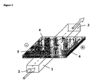
- Figure 1 shows a schematic representation of an example of separation device and illustrates the purification concept.
- the device consists of a chamber 1 containing the solution to purify with one inlet 2 and one outlet 3 at each extremity of the chamber, of a chemical buffering system 4 in contact with a portion of the chamber and of two electrodes (a cathode 5 and an anode 6) that are only in contact with the chemical buffering system and placed parallel to the chamber.
- the black arrows indicate the penetration of positively (versus cathode) or negatively (versus anode) charged compounds into the chemical buffering system upon application of an electrical field between the two electrodes, whereas the white arrows indicate that a flow of solution can be induced in the chamber.
- a cross section of the device, composed of a chemical buffering system as the cover of a channel is simulated, and the migration current is calculated in each point of the section.
- a stationary algorithm is used for the potential distribution.
- the simulations can be run using a commercial finite element software, Flux Expert® (Simulog, France) operating on a Unix workstation (Silicon Graphics Indigo 2 Solid Impact 10000 with 640 Mb RAM).
- a potential difference is applied between the two electrodes, which allows the prediction of the potential distribution.
- Figure 2AI shows that the potential distribution in the solution corresponding to the segment under the gel is closely similar to that in the chemical buffering system.
- a potential gradient is also created in the chemical buffering system, which can lead to a pre-migration of proteins in the solution depending on their charge.
- the current vectors indicate that the current is also transported through the solution. The vectors are similar in the middle of the structure and lead to an equal current flow. At the interface between the chemical buffering system and the solution, it is clearly demonstrated that a current flow takes place from the solution to the chemical buffering system.
- the concept of the separation and purification device of the present invention may be demostrated. Even if the potential is only applied to the chemical buffering system, the analyte solution adjacent to it is affected by this potential, and a migration of charged compounds (for example proteins) is induced.
- the two cases differ only in their effectiveness.
- a higher conductivity is considered, corresponding to, for example, a buffered protein solution. This is certainly more desirable for the protein stability and if the charge of some proteins have to be pre-selected for an isoelectric separation experiment.
- the first case favours protein migration and therefore also the effectiveness of the purification device as nearly 100% of the current is carried by proteins in, for example, a non-buffered solution (sample diluted in water).
- Example 2 Electrophoretic Separation and Purification in a Non-Buffered Solution
- IEF protein marker standard is obtainable from BioRad (Herkules, US). Equine cytochrome c, ⁇ -lactoglobuline A and B, trypsin inhibitor and equine myoglobin can be purchased from Sigma. Immobiline DryPlates pH range (4.5-5.4 and 4-7, 11 cm) are obtainable from Pharmacia Amersham. The reagents for capillary isoelectric focusing (CIEF) are all obtainable from BioRad.
- a plastic holder can be constructed in such a manner that the solution to purify can be pumped through the device containing the chamber contacting the chemical buffering system (which is an immobiline gel in the present case).
- Figure 2 shows a photograph of a prototype of separation and purification device that has such an arrangement.
- the chamber 1 possesses one inlet 2 and one outlet 3 that are connected to teflon tubes and a peristaltic pump (not shown) in order to let the analyte solution flow through the device.
- the chemical buffering system 4 is an immobilised pH gradient (IPG) gel placed above the chamber.
- IPG immobilised pH gradient
- the cathode 5 and the anode 6 are placed in contact only with the IPG gel, close to the o-ring.
- These electrodes are made of thin platinum wires, so that they can be integrated above the o-ring without generating any leakage in the device.
- the gel re-swells in the device, it encloses the electrodes completely and prevents the analyte solution from touching the electrodes. Re-swelling of the gels can be achieved for 1h up to overnight in water or in the buffer system in which the purification experiment can be carried out.
- the different protein solutions (1ml total volume) can be applied to the device using the peristaltic pump. Before the experiment, the solution can be circulated for at least 2 min, and a sample of 100 ⁇ l can be taken for CIEF. A constant voltage varying from 30-100 V according to the experiment can then be applied using a high voltage power supply (Spellmann, CZE1000, New York, US). Voltage and current can be recorded with a LabVIEW 5 program operated on a Digital PC and a data acquisition board (Lab PC+, National Instruments, US).
- a Biofocus 3000 apparatus (BioRad, Hercules, US) can be used for CIEF analysis using BioCap XL coated capillaries (ID 50 ⁇ m, BioRad).
- the protein samples can be diluted in ampholytes (Bio-Lyte, BioRad) and analysed using BioRad IEF catholyte, anolyte and mobiliser.
- the samples can be ultracentrifugated with Biomax 5kDa filters (Millipore, Bedford, Massachusetts, US) prior to dilution in ampholytes, in order to guarantee sufficient concentration of proteins for the CIEF analysis.
- Digital photographs of the dried immobiline gels and the device after the experiments can be taken with a digital camera (Fuji MX-700, Fuji Photo Film, Tokio, Japan) and treated with Adobe Photoshop software.
- an immobiline gel of a pH range between 6.9-7.1 can be integrated in a prototype of device as claimed by the present invention (see Figure 3).
- a solution of protein IEF markers in water (concentration of approx. 150mg/ml, protein composition see Table 1) can be applied and continuously circulated through the device of Figure 3 using a peristaltic pump at a constant pump rate (0.6 ml/min).
- a photograph of the immobiline gel after 1 hour purification upon application of an electrical potential of 100 V is shown in Figure 4.
- the portion of the IPG gel in contact with the analyte solution has a pH of 7 ⁇ 0.14.
- This figure shows a blue band 9, indicating the migration of the blue coloured protein phycocyanin towards the anode and a brown band 10, indicating cytochrome c, myoglobin and haemoglobin migrating towards the cathode.
- the proteins are concentrated in bands which demonstrate an electrophoretic focalisation mechanism. This clearly indicates that protein migration is induced from the solution to the gel, although the electrical potential is applied from electrodes only in contact with the gel. This also empirically confirms that the above simulation data agree with the experiment.
- Example 2.2 Purification of beta-Lactoglobuline B and Phycocyanin from a IEF Marker Solution
- the aim of this experiment is to recover beta-lactoglobulines A and B in solution.
- proteins with 5.0 ⁇ pI ⁇ 5.4 are either charged negatively in the gel near the cathode and repelled (pH in gel > pI), as illustrated by the proteins of type A in Figure 6B.
- these proteins of type A are positively charged (pH in gel ⁇ pI) and again repelled. In this manner, they cannot be extracted from the analyte solution.
- All other proteins with pI>5.4 are positively charged and attracted to the cathode (proteins of type B in Figure 6B), whereas all proteins with pI ⁇ 5.0 are attracted by the anode (proteins of type C in Fgiure 6B).
- the proteins to be purified are in minimal contact to the immobiline matrix, which reduces possible effect the polyacrylamide matrix could have on the proteins. They can be recovered easily in solution for further analysis. No extraction with chemicals needs to be carried out, minimising the effect of chemicals to the protein of interest. This fact also reduces the purification time. We could show here that the purification of microgram quantities can be carried out in 1h. It may even be enhanced with the use of a cooling device or a different geometry ensuring less current flow through the device. This would allow the application of a higher electrical potential.
- Example 3 Electrophoretic Separation in a Buffered Solution
- the solution of the protein markers of Table 1 is adjusted to a given pH.
- An acetate buffer (0.01 M) with a pH of 4.6 is used for this purpose.
- This pH corresponds to the pI of phycocyanin which is contained in the IEF marker standard (see Table 1).
- the pH range of the gel varied between 4.5-4.58 and 4.58-4.66.
- the current is set constant to 300 ⁇ A, which is the upper limit of the power supply.
- After several hours of electrical potential application only very little protein is visible in the gel (results not shown). These proteins are very diffuse and not focused in a band as in the above experiments. Also, bubble formation is enhanced, thereby causing a certain destruction of the gel in the device.
- a device similar to that shown in Figure 3 can be coupled to a mass spectrometer (LCQ-DUO, Finnigan) for on-line detection of the compound or compounds of interest.
- LCQ-DUO mass spectrometer
- a mixture of 80 ⁇ M catechine and 20 ⁇ M methylene blue can be pumped through the electrophoretic separation device at a rate of 1 mL/min (using a peristaltic pump from Ismatec).
- the device contains a chemical buffering system made of an IPG gel of pH 5.5 to 6.5, so that the portion of the gel in contact with the chamber exhibits the pH range 6-6.15.
- the outlet end of the chamber is connected by tubings to the injection system of a LCQ-DUO mass spectrometer for on-line analysis of the solution.
- Catechine is a well-known mass marker that is neutral between pH 6 and 6.15, whereas methylene blue is a permanent cation.
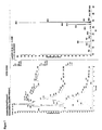
- methylene blue is extracted out of the analyte solution and penetrates into the IPG gel upon application of an electrical potential (for example 300 V). In this manner, methylene blue is eliminated from the solution, and the catechine is purified. This is evidenced in Figures 7 and 8 that show the mass spectrogram of the analyte solution before and, respectively, after electrophoretic purification.
- the device of the present invention can be coupled to a mass spectrometer for on-line detection of the purified solution. In this manner, further separation or detection of the purified solution can be easily conducted. In some applications, the purified fractions can also be collected in another support before further analysis, like for instance a MALDI (matrix assisted laser desorption ionisation) plate.
- MALDI matrix assisted laser desorption ionisation
- N-acetyl Eglin C is obtainable by recombinant DNA techniques containing two isoforms (one in basic pH and one in acid pH range).
- a water solution of 1mg/mL N-acetyl Eglin C can be recycled in the device of the present invention and run constantly at 1000 volts for 1 hour on an immobilsed pH gradient gel at pH 5.5 (pI of N-acetyl Eglin C).
- the device of the present invention does not require a chamber with inlet and outlet ends, but only a reservoir to introduce the analyte solution and retrieve it.
- Figure 9 shows a schematic representation of the set-up used for the electrophoretic separation in a static mode in a device where the inlet and outlet ends are merged, so that the chamber 31 is used as a reservoir in which the analyte solution can be introduced before purification and retrieved after purification.
- the analyte solution is only in contact with the chemical buffering system 32, and the electrical potential is applied through the anode 33 and the cathode 34 that are introduced in two reservoirs 35 and 36.
- the black arrow indicates the direction of the pH gradient introduced in the chemical buffering system.
- an electrophoretic separation device similar to that shown in Figure 9 which includes an immobilised pH gradient (IPG) gel serving as chemical buffering system and a chamber containing three sub-chambers consisting of small plastic tubes that are placed on the top of the IPG gel and disposed along the direction of the pH gradient.
- IPG immobilised pH gradient
- the analyte solution can be introduced into the central subchamber, whereas the two other subchambers are filled with water and contain each an electrode so as to serve as cathodic and anodic reservoirs, respectively. In this manner, the electrodes are not directly in contact with the analyte solution.
- the electrical field has to pass through the IPG gel, and a portion of the electric field penetrates into the subchamber containing the analyte solution to purify.
- an immobiline gel (pH range 4-7) can be reswelled in water overnight at room temperature.
- Three plastic wells (1 cm diameter) with holes (0.8 cm in diameter) opened in their bottom can be placed on top of the IPG gel, respectively on the pH 4.5, pH 5.5 and pH 6 lines.
- One hundred ⁇ L of a 300 ⁇ M methylene blue and 10 mM phenol red water solution can then be deposited in the central well in contact with the gel at pH 6.
- Two platinum electrodes can be respectively placed in the right and left side wells which are filled with water.
- the solutions in the anodic and cathodic reservoirs can be slightly coloured at the end of the purification. In such a case, this indicates that part of the methylene blue and part of the phenol red are extracted out of the IPG gel into the anodic and, repectively, the cathodic reservoirs, thereby allowing to recover in solution the compounds that have been extracted from the analyte solution into the chemical buffering system.
- This can be useful in many applications and demonstrates one interest of disposing a plurality of sub-chambers in the separation device so as to collect various purified fractions, as specified in some embodiments of the present invention.
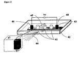
- FIG. 11 is a schematic representation of the set-up that can be used for the electrophoretic separation in a static mode with on-line detection or connection to a further separation step.
- the device is supported in a plastic support 40 containing the chamber 41 in contact with the chemical buffering system 42.
- the chamber is made of a series of subchambers 41 in which the inlet and outlet ends are merged, so that said subchamber are used as reservoirs in which the analyte solution can be introduced before purification and retrieved after purification. Only three subchambers are represented here, but there is no limitation in the number, disposition and shape of these subchambers.
- Two supplementary reservoirs 43 and 44 are used to introduce the electrodes serving to apply the electrical field necessary for performing the electrophoretic purification.
- the subchambers also contain a supplementary connection system 45 (only one shown) for the coupling to another apparatus 47 serving as supplementary separation step or as a detector.
- the figure shows that an electrical potential can be applied between the subchambers (or a given position in the connection system) and the entrance of the apparatus 47 in order to control the hydrodynamic flow of the purified solutions and/or to generate an electrospray 46, thereby permitting detection of the compounds of interest present in the purified analytical solution.
- the subchambers of the devices described in the present experiment can contain a connection (like for example an aperture, a groove, a sealed tube, a capillary, a sealed micro-channel or any other coupling system) that allows on-line introduction or injection of the purified solution into another detection system (see Figure 11 for an example).
- a connection like for example an aperture, a groove, a sealed tube, a capillary, a sealed micro-channel or any other coupling system
- a connection like for example an aperture, a groove, a sealed tube, a capillary, a sealed micro-channel or any other coupling system
- a connection like for example an aperture, a groove, a sealed tube, a capillary, a sealed micro-channel or any other coupling system
- Such a system can be demonstrated with a conventional liquid chromatograph that is used for example to further separate a cellular extract that has been purified by the electrophoretic method of the present invention and that contains several compounds of interest that need to be identified individually.
Landscapes
- Health & Medical Sciences (AREA)
- Life Sciences & Earth Sciences (AREA)
- Molecular Biology (AREA)
- Chemical & Material Sciences (AREA)
- Chemical Kinetics & Catalysis (AREA)
- Electrochemistry (AREA)
- Physics & Mathematics (AREA)
- Analytical Chemistry (AREA)
- Biochemistry (AREA)
- General Health & Medical Sciences (AREA)
- General Physics & Mathematics (AREA)
- Immunology (AREA)
- Pathology (AREA)
- Electrostatic Separation (AREA)
- Investigating Or Analysing Biological Materials (AREA)
- Peptides Or Proteins (AREA)
- Sampling And Sample Adjustment (AREA)
Claims (31)
- Dispositif destiné à la séparation et purification électrophorétiques de composés chargés et neutres dans une solution d'analytes, ledit dispositif comprenant :(a) une chambre,
une partie d'au moins une paroi de la chambre étant composée d'un système de tamponnage chimique, ledit système de tamponnage chimique définissant un pH souhaité ou un gradient de pH souhaité dans sa partie en contact avec ladite solution d'analytes, et ledit système de tamponnage chimique étant sélectionné parmi un gel d'immobilines, ou un fluide solidifié dans l'un parmi une matrice polymère, un verre fritté, une membrane poreuse, un filtre, ou une combinaison de ceux-ci.(b) un moyen pour produire une différence de potentiel à travers ledit système de tamponnage chimique pour générer un champ électrique qui est distribué le long dudit système de tamponnage chimique et qui pénètre dans ladite solution d'analytes, ce par quoi lesdits composés chargés et neutres peuvent être séparés distinctivement par l'extraction desdits composés chargés dans ledit système de tamponnage chimique ;(c) un moyen pour recueillir les fractions séparées, si souhaité en solution, telle qu'une solution exempte d'ampholyte ou de tampon ; et(d) facultativement, un moyen pour recycler les fractions séparées. - Dispositif selon la revendication 1, caractérisé en ce que ladite chambre présente une entrée et une sortie raccordées à un système d'écoulement hydraulique dans lequel la solution d'analytes peut s'écouler à travers ladite chambre.
- Dispositif selon la revendication 1 ou la revendication 2, caractérisé en ce que ladite chambre présente une entrée unique et une pluralité de sorties, permettant ainsi de recueillir des fractions en différentes parties du système de tamponnage chimique.
- Dispositif selon l'une quelconque des revendications précédentes, caractérisé en ce que la direction du courant électrique est perpendiculaire à la direction de l'écoulement de la solution d'analytes.
- Dispositif selon la revendication 1, caractérisé en ce que la chambre présente une entrée et une sortie qui se confondent de sorte que ladite chambre constitue un réservoir dans lequel la solution d'analytes peut être introduite avant séparation et purification et duquel la solution purifiée peut être récupérée.
- Dispositif selon l'une quelconque des revendications précédentes, caractérisé en ce que ladite chambre est composée d'une pluralité de sous-chambres.
- Dispositif selon la revendication 6, caractérisé en ce que lesdites sous-chambres sont interconnectées.
- Dispositif selon la revendication 6 ou la revendication 7, caractérisé en ce que au moins une sous-chambre ne contient pas la solution d'analytes à purifier.
- Dispositif selon la revendication 8, caractérisé en ce que au moins une sous-chambre est utilisée pour récupérer en solution un (des) composé(s) qui ont été extraits de la solution d'analytes et qui ont migré à l'intérieur du système de tamponnage chimique.
- Dispositif selon l'une quelconque des revendications précédentes, caractérisé en ce que ledit moyen de production dudit courant électrique à travers ledit système de tamponnage chimique est intégré dans le système de tamponnage chimique.
- Dispositif selon l'une quelconque des revendications précédentes, caractérisé en ce que le système de tamponnage chimique est jetable.
- Dispositif selon l'une quelconque des revendications précédentes, caractérisé en ce que le pH souhaité ou le gradient de pH souhaité dans ledit système de tamponnage chimique est produit en utilisant des molécules de tampon liées par covalence.
- Dispositif selon l'une quelconque des revendications précédentes, caractérisé en ce que ledit système est capable de séparer isoélectriquement le composé ou les composés d'intérêt à une valeur de pH définie ou dans une plage de pH définie.
- Dispositif selon l'une quelconque des revendications précédentes, caractérisé en ce que le système de tamponnage chimique est capable de séparer des composés de pI différents, tels que des composés présentant des différences de pI inférieures à 0,1, des composés présentant des différences de pI inférieures à 0,01 et jusqu'à des différences de pI de 0,001, et ainsi ledit système de tamponnage chimique est capable d'obtenir différents degrés souhaités de purification.
- Dispositif selon l'une quelconque des revendications précédentes, caractérisé en ce que le système de tamponnage chimique contient un moyen d'identification et/ou de quantification directe(s) d'un composé ou d'une classe de composés qui ont été extraits de la solution d'analytes en dehors de la chambre.
- Dispositif selon la revendication 15, caractérisé en ce que ledit moyen d'identification et/ou de quantification est basé sur la production de lumière, l'absorption de lumière, la réaction avec un agent de transfert (« blotting agent ») ou un marqueur (« label »), la génération d'une espèce électroactive ou la reconnaissance moléculaire spécifique de composés comme la formation d'un complexe antigène-anticorps ou une réaction enzymatique.
- Dispositif selon l'une quelconque des revendications précédentes, comprenant en outre un moyen pour arrêter l'adsorption directe des composés neutres sur la paroi du système de tamponnage chimique, ledit moyen comprenant un séparateur à membrane fine.
- Dispositif selon l'une quelconque des revendications précédentes, comprenant en outre des moyens pour régler la température dudit dispositif et de la solution d'analytes.
- Dispositif selon l'une quelconque des revendications précédentes, comprenant en outre un moyen de couplage permettant de faire passer la solution d'analytes purifiée et/ou les composés chargés récupérés du dispositif dans d'autres systèmes de séparation et/ou de détection.
- Dispositif selon l'une quelconque des revendications précédentes, caractérisé en ce qu'il est multiplexé pour réaliser de manière simultanée et/ou en parallèle la séparation et la purification électrophorétiques de composés chargés et neutres.
- Procédé de séparation et purification électrophorétiques de composés chargés et neutres dans une solution d'analytes et de collecte des fractions séparées en utilisant le dispositif selon l'une quelconque des revendications précédentes.
- Procédé selon la revendication 21, caractérisé en ce que lesdits composés sont récupérables en solution, facultativement dans une solution exempte d'ampholytes ou de tampon.
- Procédé selon la revendication 21 ou la revendication 22, caractérisé en ce que les composés sont des composés biologiques tels que des composés organiques, par exemple des protéines ou des dérivés protéiques ou des isoformes.
- Procédé selon l'une quelconque des revendications 21 à 23, caractérisé en ce que la solution d'analytes contient un solvant organique ou est non-aqueuse.
- Procédé selon l'une quelconque des revendications 21 à 24, caractérisé en ce que le dispositif est utilisé pour charger le système de tamponnage chimique avec des composés d'intérêt.
- Procédé selon la revendication 25, caractérisé en ce que la solution d'analytes est renouvelée dans la chambre afin d'accumuler des composés d'intérêt dans le système de tamponnage chimique.
- Kit comprenant un dispositif selon l'une quelconque des revendications 1 à 20 avec des instructions pour les séparation et purification électrophorétiques de composés chargés et neutres d'une solution d'analytes.
- Kit selon la revendication 27, caractérisé en ce que lesdits composés sont récupérables en solution, telle qu'une solution exempte d'ampholytes ou exempte de tampon.
- Kit selon la revendication 27 ou la revendication 28, comprenant des produits chimiques spécifiques qu'il faut mélanger avec la solution d'analytes pour les séparation et purification électrophorétiques.
- Kit selon l'une quelconque des revendications 27 à 29, comprenant des produits chimiques spécifiques et/ou un système de séparation qui est/sont nécessaire(s) pour préparer la solution d'analytes avant les séparation et purification électrophorétiques.
- Kit selon la revendication 30, caractérisée en ce que ledit système de séparation est une membrane de coupure (« cut-off membrane ») et/ou un système de dessalage.
Applications Claiming Priority (3)
| Application Number | Priority Date | Filing Date | Title |
|---|---|---|---|
| GB0010957 | 2000-05-05 | ||
| GBGB0010957.9A GB0010957D0 (en) | 2000-05-05 | 2000-05-05 | Compound & method |
| PCT/EP2001/005704 WO2001086279A1 (fr) | 2000-05-05 | 2001-05-04 | Separation de composes par electrophorese |
Publications (2)
| Publication Number | Publication Date |
|---|---|
| EP1281073A1 EP1281073A1 (fr) | 2003-02-05 |
| EP1281073B1 true EP1281073B1 (fr) | 2005-07-27 |
Family
ID=9891094
Family Applications (1)
| Application Number | Title | Priority Date | Filing Date |
|---|---|---|---|
| EP01945155A Expired - Lifetime EP1281073B1 (fr) | 2000-05-05 | 2001-05-04 | Separation de composes par electrophorese |
Country Status (7)
| Country | Link |
|---|---|
| US (1) | US7615354B2 (fr) |
| EP (1) | EP1281073B1 (fr) |
| JP (1) | JP4754759B2 (fr) |
| AU (2) | AU6745501A (fr) |
| DE (1) | DE60112276T2 (fr) |
| GB (1) | GB0010957D0 (fr) |
| WO (1) | WO2001086279A1 (fr) |
Cited By (1)
| Publication number | Priority date | Publication date | Assignee | Title |
|---|---|---|---|---|
| CN101512334B (zh) * | 2006-06-20 | 2013-08-07 | 贝克顿迪肯森公司 | 用电泳来分离和去除某些蛋白和颗粒的方法与装置 |
Families Citing this family (30)
| Publication number | Priority date | Publication date | Assignee | Title |
|---|---|---|---|---|
| GB0121189D0 (en) * | 2001-08-31 | 2001-10-24 | Diagnoswiss Sa | Apparatus and method for separating an analyte |
| GB0226160D0 (en) * | 2002-11-08 | 2002-12-18 | Diagnoswiss Sa | Apparatus for dispensing a sample in electrospray mass spectrometers |
| FR2847343B1 (fr) * | 2002-11-18 | 2005-12-09 | Centre Nat Rech Scient | Dispositif et procede d'electrophorese |
| GB0300820D0 (en) * | 2003-01-14 | 2003-02-12 | Diagnoswiss Sa | Membrane-microchannel strip |
| WO2005026665A2 (fr) * | 2003-09-15 | 2005-03-24 | Diagnoswiss S.A. | Dispositif de surveillance d'ecoulement microfluidique |
| EP1668351A1 (fr) * | 2003-09-24 | 2006-06-14 | Agilent Technologies Inc | Extraction de molecules au moyen d'une structure |
| FR2867695B1 (fr) | 2004-03-18 | 2006-12-29 | Portmann Instr | Dispositif et procede de filtration et/ou de separation de molecules |
| JP4492212B2 (ja) * | 2004-05-20 | 2010-06-30 | 株式会社島津製作所 | 等電点電気泳動チップ及び装置 |
| JP4424076B2 (ja) * | 2004-06-04 | 2010-03-03 | 株式会社島津製作所 | 脱塩用マイクロチップおよび脱塩装置 |
| DE212005000044U1 (de) * | 2004-08-25 | 2007-04-05 | Agilent Technologies Inc., Santa Clara | Elektrophoretische Separation in einem bewegten Fluid |
| US20070240986A1 (en) * | 2004-11-12 | 2007-10-18 | Diagnoswiss S.A. | Microfluidic Device with Minimized Ohmic Resistance |
| ITPD20040301A1 (it) * | 2004-11-26 | 2005-02-26 | Dimensional Srl P | Metodo ed apparato per la separazione simultanea di molecole biologiche mediante elettroforesi bidimensionale |
| WO2006063625A1 (fr) * | 2004-12-17 | 2006-06-22 | Agilent Technologies, Inc. | Fractionnement faisant appel a une electroelution |
| WO2007051492A1 (fr) | 2005-11-02 | 2007-05-10 | Agilent Technologies, Inc. | Récupération d’un échantillon sous l’action d’une force dans une électrophorèse gel |
| GB0607205D0 (en) * | 2006-04-10 | 2006-05-17 | Diagnoswiss Sa | Miniaturised biosensor with optimized anperimetric detection |
| AU2007243994B2 (en) * | 2006-04-27 | 2012-08-02 | Ge Healthcare Bio-Sciences Ab | Electrodic bridge |
| GB0712795D0 (en) * | 2007-07-02 | 2007-08-08 | Ecole Polytechnique Federale De | Solid phase extraction and ionization device |
| EP2146200A1 (fr) | 2008-07-16 | 2010-01-20 | Agilent Technologies, Inc. | Dispositif et procédé pour pour focalisation isoélectrique |
| US9766207B2 (en) | 2011-11-04 | 2017-09-19 | Bio-Rad Laboratories, Inc. | Affinity methods and compositions employing electronic control of pH |
| US9234875B2 (en) | 2011-11-04 | 2016-01-12 | Bio-Rad Laboratories, Inc. | Simultaneous purification of cell components |
| EP2788746B1 (fr) | 2011-11-22 | 2018-10-24 | Stephen G. Haralampu | Dispositif microfluidique à blocage d'écoulement, et procédé de séparation de mélanges d'analytes complexes basé sur la charge |
| EP2801103B1 (fr) | 2012-01-06 | 2018-10-03 | Ecole Polytechnique Federale de Lausanne (EPFL) | Méthode d'ionisation par pulvérisation électrostatique |
| US9658195B2 (en) | 2012-02-15 | 2017-05-23 | Bio-Rad Laboratories, Inc. | Electronic control of pH and ionic strength |
| US9321012B2 (en) | 2012-04-04 | 2016-04-26 | Bio-Rad Laboratories, Inc. | Electronic protein fractionation |
| US9159537B2 (en) * | 2012-05-03 | 2015-10-13 | University Of Notre Dame Du Lac | Method for analyzing sample components |
| JP6507424B2 (ja) * | 2015-02-26 | 2019-05-08 | 三菱日立パワーシステムズ株式会社 | 塩分測定方法及び塩分捕集装置 |
| WO2017044614A1 (fr) * | 2015-09-11 | 2017-03-16 | The Regents Of The University Of California | Réseaux de focalisation isoélectrique et leurs procédés d'utilisation |
| US9702851B1 (en) * | 2016-06-17 | 2017-07-11 | Woodham Biotechnology Holdings, LLC | Gel electrophoresis and transfer combination using conductive polymers and method of use |
| EP4041427A4 (fr) * | 2019-10-09 | 2023-11-08 | ProteinSimple | Procédé d'électrophorèse à écoulement libre en canal unique, à réglage de ph séquentiel |
| US20220334033A1 (en) * | 2021-04-20 | 2022-10-20 | Brown University | Electrical dissociation of tissue samples into single cells and/or smaller groups of cells |
Family Cites Families (22)
| Publication number | Priority date | Publication date | Assignee | Title |
|---|---|---|---|---|
| US2815320A (en) * | 1953-10-23 | 1957-12-03 | Kollsman Paul | Method of and apparatus for treating ionic fluids by dialysis |
| DE2051715B2 (de) * | 1970-10-21 | 1976-01-15 | Trennkammer fuer die kontinuierliche ablenkungselektrophorese | |
| US3719580A (en) | 1971-06-04 | 1973-03-06 | R Roberts | Electrophoretic apparatus |
| GB1422118A (en) | 1972-01-04 | 1976-01-21 | Bovril Ltd | Vertical gel electrophoresis apparatus |
| US3888758A (en) | 1973-06-28 | 1975-06-10 | Sheik Arshad Saeed | Apparatus for large scale gel electrophoresis |
| US4148703A (en) | 1976-02-11 | 1979-04-10 | Morton Weintraub | Method of electrophoretic purification of enzymes and peptides by means of an adjustable, specialized, geometrically located electrode system |
| CA1238296A (fr) | 1984-08-02 | 1988-06-21 | Claude Hamelin | Systeme d'electrophorese de plaques de gel d'agarose |
| EP0287513B1 (fr) * | 1987-04-11 | 1992-12-02 | Ciba-Geigy Ag | Procédé de focalisation isoélectrique et moyens pour la mise en oeuvre de ce procédé |
| US5114555A (en) * | 1988-01-05 | 1992-05-19 | Monsanto Company | Continuous isoelectric separation |
| US5126022A (en) | 1990-02-28 | 1992-06-30 | Soane Tecnologies, Inc. | Method and device for moving molecules by the application of a plurality of electrical fields |
| US5104512A (en) | 1990-05-14 | 1992-04-14 | Labintelligence, Inc. | Gel electrophoresis system |
| US5149418A (en) | 1991-09-04 | 1992-09-22 | Apogee Designs, Ltd. | Vertical gel electrophoresis apparatus having universal gel assembly support structure |
| NO315930B1 (no) * | 1995-01-18 | 2003-11-17 | Picower Inst For Medical Res T | Anvendelse av tiazoliumforbindelser ved fremstilling av farmasöytiske preparater, preparater som inneholder forbindelsene, samt nyetiazoliumforbindelser |
| IT1272932B (it) | 1995-01-24 | 1997-07-01 | Pier Giorgio Righetti | Reattore ad enzima immobilizzato |
| US5540826A (en) * | 1995-03-15 | 1996-07-30 | Protein Technologies, Inc. | Multi-channel separation device |
| US5856100A (en) | 1995-12-08 | 1999-01-05 | The Institute Of Physical And Chemical Research | Method for purification and transfer to separation/detection systems of DNA sequencing samples and plates used therefor |
| US5773645A (en) * | 1997-05-05 | 1998-06-30 | Bio-Rad Laboratories, Inc. | Two-dimensional electrophoresis device |
| US6013165A (en) * | 1998-05-22 | 2000-01-11 | Lynx Therapeutics, Inc. | Electrophoresis apparatus and method |
| AUPP576598A0 (en) | 1998-09-07 | 1998-10-01 | Life Therapeutics Limited | Cassette for macromolecule purification |
| WO2000074850A2 (fr) | 1999-06-03 | 2000-12-14 | University Of Washington | Dispositifs microfluidiques pour electrophorese transversale et focalisation isoelectrique |
| US6638408B1 (en) | 2000-04-03 | 2003-10-28 | The Wistar Institute | Method and device for separation of charged molecules by solution isoelectric focusing |
| US6706162B1 (en) * | 2000-09-25 | 2004-03-16 | Applera Corporation | High speed, high resolution compositions, methods, and kits for capillary electrophoresis |
-
2000
- 2000-05-05 GB GBGB0010957.9A patent/GB0010957D0/en not_active Ceased
-
2001
- 2001-05-04 US US10/275,041 patent/US7615354B2/en not_active Expired - Fee Related
- 2001-05-04 AU AU6745501A patent/AU6745501A/xx active Pending
- 2001-05-04 WO PCT/EP2001/005704 patent/WO2001086279A1/fr not_active Ceased
- 2001-05-04 JP JP2001583172A patent/JP4754759B2/ja not_active Expired - Fee Related
- 2001-05-04 DE DE60112276T patent/DE60112276T2/de not_active Expired - Lifetime
- 2001-05-04 EP EP01945155A patent/EP1281073B1/fr not_active Expired - Lifetime
- 2001-05-04 AU AU2001267455A patent/AU2001267455B2/en not_active Ceased
Cited By (1)
| Publication number | Priority date | Publication date | Assignee | Title |
|---|---|---|---|---|
| CN101512334B (zh) * | 2006-06-20 | 2013-08-07 | 贝克顿迪肯森公司 | 用电泳来分离和去除某些蛋白和颗粒的方法与装置 |
Also Published As
| Publication number | Publication date |
|---|---|
| GB0010957D0 (en) | 2000-06-28 |
| WO2001086279A1 (fr) | 2001-11-15 |
| DE60112276D1 (de) | 2005-09-01 |
| AU6745501A (en) | 2001-11-20 |
| US20030104449A1 (en) | 2003-06-05 |
| JP2003532894A (ja) | 2003-11-05 |
| US7615354B2 (en) | 2009-11-10 |
| JP4754759B2 (ja) | 2011-08-24 |
| DE60112276T2 (de) | 2006-04-20 |
| AU2001267455B2 (en) | 2005-12-08 |
| EP1281073A1 (fr) | 2003-02-05 |
Similar Documents
| Publication | Publication Date | Title |
|---|---|---|
| EP1281073B1 (fr) | Separation de composes par electrophorese | |
| AU2001267455A1 (en) | Electrophoretic separation of compounds | |
| Ros et al. | Protein purification by Off‐Gel electrophoresis | |
| EP1421373B1 (fr) | Appareil et procede de separation d'un analyte | |
| Schwer et al. | Analytical and micropreparative separation of peptides by capillary zone electrophoresis using discontinuous buffer systems | |
| Herr et al. | On-chip coupling of isoelectric focusing and free solution electrophoresis for multidimensional separations | |
| Zuo et al. | Comprehensive analysis of complex proteomes using microscale solution isoelectrofocusing prior to narrow pH range two‐dimensional electrophoresis | |
| Shimura | Recent advances in IEF in capillary tubes and microchips | |
| Stroink et al. | On-line multidimensional liquid chromatography and capillary electrophoresis systems for peptides and proteins | |
| US20040031683A1 (en) | Method for separating and detecting proteins by means of electrophoresis | |
| US6676819B1 (en) | Methods and apparatus for automatic on-line multi-dimensional electrophoresis | |
| Zhao et al. | Microchip electrophoresis with chemiluminescence detection for assaying ascorbic acid and amino acids in single cells | |
| Righetti et al. | Recent advances in electrophoretic techniques for the characterization of protein biomolecules: A poker of aces | |
| US9182372B2 (en) | Stopped-flow, micro-fluidic device and method for the charge-based separation of complex analyte mixtures | |
| Srinivas | Introduction to protein electrophoresis | |
| Wei et al. | Two‐dimensional separation system by on‐line hyphenation of capillary isoelectric focusing with pressurized capillary electrochromatography for peptide and protein mapping | |
| Maity et al. | Electrophoretic techniques | |
| Li et al. | A stable and high-resolution isoelectric focusing capillary array device for micropreparative separation of proteins | |
| Weber et al. | Free-flow electrophoresis system for proteomics applications | |
| Fang et al. | Investigation of a microfluidic free-flow electrophoresis chip of glass substrate with integrated indium tin oxide electrodes | |
| Brod et al. | Charge-based separation of proteins and peptides by electrically induced dynamic pH profiles | |
| Changa et al. | Advanced capillary and microchip electrophoretic techniques for proteomics | |
| Burgi et al. | Capillary electrophoresis of proteins and peptides | |
| AU2002337098B2 (en) | Apparatus and method for separating an analyte | |
| Patton et al. | Taking a walk on the wild side with planar electrochromatography and thin‐layer electrophoresis: of peptides, proteins, and proteomics |
Legal Events
| Date | Code | Title | Description |
|---|---|---|---|
| PUAI | Public reference made under article 153(3) epc to a published international application that has entered the european phase |
Free format text: ORIGINAL CODE: 0009012 |
|
| 17P | Request for examination filed |
Effective date: 20021122 |
|
| AK | Designated contracting states |
Designated state(s): AT BE CH CY DE DK ES FI FR GB GR IE IT LI LU MC NL PT SE TR |
|
| AX | Request for extension of the european patent |
Extension state: AL LT LV MK RO SI |
|
| 111L | Licence recorded |
Free format text: 0100 DIAGNOSWISS SA, OF C/O CIMO SA Effective date: 20030225 |
|
| 111L | Licence recorded |
Free format text: 0100 DIAGNOSWISS SA, OF C/O CIMO SA Effective date: 20030225 Free format text: 0101 AGILENT TECHNOLOGIES DEUTSCHLAND GMBH Effective date: 20030802 |
|
| RBV | Designated contracting states (corrected) |
Designated state(s): AT BE CH CY DE FR GB LI |
|
| GRAP | Despatch of communication of intention to grant a patent |
Free format text: ORIGINAL CODE: EPIDOSNIGR1 |
|
| RBV | Designated contracting states (corrected) |
Designated state(s): CH DE FR GB LI |
|
| GRAS | Grant fee paid |
Free format text: ORIGINAL CODE: EPIDOSNIGR3 |
|
| GRAA | (expected) grant |
Free format text: ORIGINAL CODE: 0009210 |
|
| AK | Designated contracting states |
Kind code of ref document: B1 Designated state(s): CH DE FR GB LI |
|
| REG | Reference to a national code |
Ref country code: GB Ref legal event code: FG4D |
|
| REG | Reference to a national code |
Ref country code: CH Ref legal event code: EP |
|
| REF | Corresponds to: |
Ref document number: 60112276 Country of ref document: DE Date of ref document: 20050901 Kind code of ref document: P |
|
| REG | Reference to a national code |
Ref country code: CH Ref legal event code: NV Representative=s name: A. BRAUN, BRAUN, HERITIER, ESCHMANN AG PATENTANWAE |
|
| ET | Fr: translation filed | ||
| PLBE | No opposition filed within time limit |
Free format text: ORIGINAL CODE: 0009261 |
|
| STAA | Information on the status of an ep patent application or granted ep patent |
Free format text: STATUS: NO OPPOSITION FILED WITHIN TIME LIMIT |
|
| 26N | No opposition filed |
Effective date: 20060428 |
|
| REG | Reference to a national code |
Ref country code: CH Ref legal event code: PFA Owner name: ECOLE POLYTECHNIQUE FEDERALE DE LAUSANNE Free format text: ECOLE POLYTECHNIQUE FEDERALE DE LAUSANNE#LABORATOIRE D'ELECTROCHIMIE#1015 LAUSANNE (CH) -TRANSFER TO- ECOLE POLYTECHNIQUE FEDERALE DE LAUSANNE#LABORATOIRE D'ELECTROCHIMIE#1015 LAUSANNE (CH) |
|
| REG | Reference to a national code |
Ref country code: CH Ref legal event code: PCAR Free format text: NEW ADDRESS: HOLBEINSTRASSE 36-38, 4051 BASEL (CH) |
|
| REG | Reference to a national code |
Ref country code: FR Ref legal event code: PLFP Year of fee payment: 15 |
|
| PGFP | Annual fee paid to national office [announced via postgrant information from national office to epo] |
Ref country code: DE Payment date: 20151130 Year of fee payment: 15 Ref country code: CH Payment date: 20151125 Year of fee payment: 15 Ref country code: GB Payment date: 20151113 Year of fee payment: 15 |
|
| PGFP | Annual fee paid to national office [announced via postgrant information from national office to epo] |
Ref country code: FR Payment date: 20151127 Year of fee payment: 15 |
|
| REG | Reference to a national code |
Ref country code: DE Ref legal event code: R119 Ref document number: 60112276 Country of ref document: DE |
|
| REG | Reference to a national code |
Ref country code: CH Ref legal event code: PL |
|
| GBPC | Gb: european patent ceased through non-payment of renewal fee |
Effective date: 20160504 |
|
| PG25 | Lapsed in a contracting state [announced via postgrant information from national office to epo] |
Ref country code: CH Free format text: LAPSE BECAUSE OF NON-PAYMENT OF DUE FEES Effective date: 20160531 Ref country code: LI Free format text: LAPSE BECAUSE OF NON-PAYMENT OF DUE FEES Effective date: 20160531 |
|
| REG | Reference to a national code |
Ref country code: FR Ref legal event code: ST Effective date: 20170131 |
|
| PG25 | Lapsed in a contracting state [announced via postgrant information from national office to epo] |
Ref country code: FR Free format text: LAPSE BECAUSE OF NON-PAYMENT OF DUE FEES Effective date: 20160531 Ref country code: DE Free format text: LAPSE BECAUSE OF NON-PAYMENT OF DUE FEES Effective date: 20161201 |
|
| PG25 | Lapsed in a contracting state [announced via postgrant information from national office to epo] |
Ref country code: GB Free format text: LAPSE BECAUSE OF NON-PAYMENT OF DUE FEES Effective date: 20160504 |
|
| REG | Reference to a national code |
Ref country code: CH Ref legal event code: PK Free format text: COMPLEMENT D'ENREGISTREMENT DE LICENCE: LICENCES EXCLUSIVES |