EP1281217B1 - Contacteur electrique tournant - Google Patents
Contacteur electrique tournant Download PDFInfo
- Publication number
- EP1281217B1 EP1281217B1 EP01929772A EP01929772A EP1281217B1 EP 1281217 B1 EP1281217 B1 EP 1281217B1 EP 01929772 A EP01929772 A EP 01929772A EP 01929772 A EP01929772 A EP 01929772A EP 1281217 B1 EP1281217 B1 EP 1281217B1
- Authority
- EP
- European Patent Office
- Prior art keywords
- conductor
- ribbon
- foam
- contactor
- ribbon conductor
- Prior art date
- Legal status (The legal status is an assumption and is not a legal conclusion. Google has not performed a legal analysis and makes no representation as to the accuracy of the status listed.)
- Expired - Lifetime
Links
- 239000006260 foam Substances 0.000 claims description 16
- 239000011810 insulating material Substances 0.000 claims description 4
- 239000000463 material Substances 0.000 claims description 3
- 239000000853 adhesive Substances 0.000 claims description 2
- 230000001070 adhesive effect Effects 0.000 claims description 2
- 239000003000 extruded plastic Substances 0.000 claims description 2
- 239000004033 plastic Substances 0.000 claims description 2
- 229920003023 plastic Polymers 0.000 claims description 2
- 239000004020 conductor Substances 0.000 description 26
- 238000000034 method Methods 0.000 description 4
- 238000001125 extrusion Methods 0.000 description 3
- 229920000728 polyester Polymers 0.000 description 3
- 239000011248 coating agent Substances 0.000 description 2
- 238000000576 coating method Methods 0.000 description 2
- -1 polyethylene Polymers 0.000 description 2
- RYGMFSIKBFXOCR-UHFFFAOYSA-N Copper Chemical compound [Cu] RYGMFSIKBFXOCR-UHFFFAOYSA-N 0.000 description 1
- 239000004698 Polyethylene Substances 0.000 description 1
- 239000004743 Polypropylene Substances 0.000 description 1
- 239000006096 absorbing agent Substances 0.000 description 1
- 230000000903 blocking effect Effects 0.000 description 1
- 229910052802 copper Inorganic materials 0.000 description 1
- 239000010949 copper Substances 0.000 description 1
- 238000013016 damping Methods 0.000 description 1
- 230000002542 deteriorative effect Effects 0.000 description 1
- 230000009977 dual effect Effects 0.000 description 1
- 238000007731 hot pressing Methods 0.000 description 1
- 238000009413 insulation Methods 0.000 description 1
- 230000014759 maintenance of location Effects 0.000 description 1
- 229920000573 polyethylene Polymers 0.000 description 1
- 229920001155 polypropylene Polymers 0.000 description 1
- 229920002635 polyurethane Polymers 0.000 description 1
- 239000004814 polyurethane Substances 0.000 description 1
- 230000000717 retained effect Effects 0.000 description 1
- 230000035939 shock Effects 0.000 description 1
Images


Classifications
-
- B—PERFORMING OPERATIONS; TRANSPORTING
- B60—VEHICLES IN GENERAL
- B60R—VEHICLES, VEHICLE FITTINGS, OR VEHICLE PARTS, NOT OTHERWISE PROVIDED FOR
- B60R16/00—Electric or fluid circuits specially adapted for vehicles and not otherwise provided for; Arrangement of elements of electric or fluid circuits specially adapted for vehicles and not otherwise provided for
- B60R16/02—Electric or fluid circuits specially adapted for vehicles and not otherwise provided for; Arrangement of elements of electric or fluid circuits specially adapted for vehicles and not otherwise provided for electric constitutive elements
- B60R16/023—Electric or fluid circuits specially adapted for vehicles and not otherwise provided for; Arrangement of elements of electric or fluid circuits specially adapted for vehicles and not otherwise provided for electric constitutive elements for transmission of signals between vehicle parts or subsystems
- B60R16/027—Electric or fluid circuits specially adapted for vehicles and not otherwise provided for; Arrangement of elements of electric or fluid circuits specially adapted for vehicles and not otherwise provided for electric constitutive elements for transmission of signals between vehicle parts or subsystems between relatively movable parts of the vehicle, e.g. between steering wheel and column
-
- H—ELECTRICITY
- H01—ELECTRIC ELEMENTS
- H01R—ELECTRICALLY-CONDUCTIVE CONNECTIONS; STRUCTURAL ASSOCIATIONS OF A PLURALITY OF MUTUALLY-INSULATED ELECTRICAL CONNECTING ELEMENTS; COUPLING DEVICES; CURRENT COLLECTORS
- H01R35/00—Flexible or turnable line connectors, i.e. the rotation angle being limited
- H01R35/02—Flexible line connectors without frictional contact members
Definitions
- the present invention relates to a rotary electrical contactor comprising a conductive tape.
- Rotary contactors are devices for electrically connecting parts pivoting with respect to each other.
- the ribbon conductor is enclosed in a housing which is delimited in particular by two parallel plates against which the upper edges and ribbon conductor support.
- One end of the ribbon conductor is attached to a stator which is located general at the periphery of the contactor.
- the other end of the ribbon conductor is connected to a rotor, most often housed inside the stator.
- the present invention aims to provide an efficient and economical solution to these problems.
- the present invention relates to a rotary electrical contactor comprising a ribbon conductor held by one of its edges against at least one coated plate of an insulating material on its face directed towards said tape conductor, characterized in that that the insulating material is foam and that the edge of the tape conductor is rounded and applied directly against this foam.
- the ribbon conductor can be put in direct contact with a foam coating covering the plates of the contactor.
- the foam is presented under the shape of a non-adhesive sheet sandwiched between the tape conductor and the plate. His low weight allows it to be left free between the conductor's edge and the face of the plate directed towards the conductor.
- the foam sheet can also be glued to the plate.
- different techniques can be used.
- One of them consists of enclosing conductive strips in a sheet of plastic material folded back on itself and forming a rounded edge at each conductor-song.
- extrusion a technique by which the conductive strips are directly coated with extruded plastic.
- extrusion a technique by which the conductive strips are directly coated with extruded plastic.
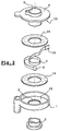
- the contactor shown in the drawing comprises, in known manner, a housing 1 in cup-shaped, pierced in the middle by an orifice 2 in which is housed a lower hub 3.
- the contactor also includes a cover 4 which is formed in one piece with an upper hub 5 extending over the entire height of the housing.
- the cover 4 fits into the housing 1, inside which it is retained by latching with the lower hub 3.
- This snap-in ensures the axial retention of the cover but leaves the latter free to pivot inside the case, accompanying a rotating shaft, as by example a shaft of a steering column supporting a steering wheel.
- the outer end 8 of the ribbon conductor is fixed to a terminal 9 integral with the housing.
- the inner end 10 of the ribbon conductor is fixed to a terminal 11 integral cover 4.
- the bottom 12 of the housing and the inner face 13 of the cover constitute plates parallels between which the ribbon conductor 7 is held, inside the cage ring finger 6.
- the bottom 12 of the housing and the inner face 13 of the cover are coated with a sheet polyurethane, polyethylene or polypropylene foam 14.
- Each foam sheet 14 is left free in the cage 6.
- the ribbon conductor 7 maintains it in the vicinity of the corresponding plate 12, 13.
- the edges of the ribbon conductor directed, one towards the cover, the other towards the bottom of the case are rounded in the direction where they have no sharp edges.
- the rounded shape of the edge is enough to prevent the foam from deteriorating or ribbon conductor blocking.
- This ribbon conductor comprises four conductive strips 15, for example in copper, overmolded in a mass 16 of polyester after extrusion. Songs 17 of the mass are rounded off by an appropriate choice of the extrusion head.
- This ribbon conductor comprises six conductive strips 18 which have been deposited on a polyester sheet laid flat.
- the polyester sheet has been folded back on itself on either side of the strips conductive to enclose them completely, the ends 20 of the sheet joining substantially in the middle of the ribbon.
- the sheet thus prepared was subjected to hot pressing, which formed bridges 21 between the conductive strips, thus providing insulation and positioning definitive of these.
- edges 22 of the ribbon thus obtained are rounded, that is to say they do not have no sharp edges.
Landscapes
- Engineering & Computer Science (AREA)
- Mechanical Engineering (AREA)
- Steering Controls (AREA)
- Push-Button Switches (AREA)
- Installation Of Indoor Wiring (AREA)
- Elimination Of Static Electricity (AREA)
Description
- une figure 1 représentant une vue en coupe axiale d'un contacteur électrique selon un mode de réalisation de l'invention,
- une figure 2 représentant une vue en perspective éclatée du contacteur de la figure 1,
- une figure 3 représentant à plus grande échelle une coupe transversale du conducteur-ruban,
- une figure 4 représentant une section transversale d'un autre conducteur-ruban.
Claims (4)
- Contacteur électrique tournant comprenant un conducteur-ruban (7) maintenu par un de ses chants (17, 22) contre au moins une plaque (12, 13) revêtue d'un matériau isolant sur sa face dirigée vers ledit conducteur-ruban, caractérisé en ce que le matériau isolant est une mousse (14) et en ce que le chant (17, 22) du conducteur-ruban est arrondi et s'applique directement contre cette mousse (14).
- Contacteur selon la revendication 1, caractérisé en ce que la mousse se présente sous la forme d'une feuille (14) non adhésive intercalée entre le conducteur-ruban (7) et la plaque (12, 13).
- Contacteur selon l'une quelconque des revendications 1 et 2, caractérisé en ce que le conducteur-ruban comprend une masse (16) de matière plastique extrudée autour de bandes conductrices (15).
- Contacteur selon l'une quelconque des revendications 1 et 2, caractérisé en ce que le conducteur-ruban est constitué par des bandes conductrices (15) déposées sur une feuille de matière plastique rabattue sur elle-même en emprisonnant les bandes.
Applications Claiming Priority (3)
| Application Number | Priority Date | Filing Date | Title |
|---|---|---|---|
| FR0005622 | 2000-05-03 | ||
| FR0005622A FR2808625B1 (fr) | 2000-05-03 | 2000-05-03 | Contacteur electrique tournant |
| PCT/FR2001/001340 WO2001084677A1 (fr) | 2000-05-03 | 2001-05-02 | Contacteur electrique tournant |
Publications (2)
| Publication Number | Publication Date |
|---|---|
| EP1281217A1 EP1281217A1 (fr) | 2003-02-05 |
| EP1281217B1 true EP1281217B1 (fr) | 2004-09-22 |
Family
ID=8849827
Family Applications (1)
| Application Number | Title | Priority Date | Filing Date |
|---|---|---|---|
| EP01929772A Expired - Lifetime EP1281217B1 (fr) | 2000-05-03 | 2001-05-02 | Contacteur electrique tournant |
Country Status (6)
| Country | Link |
|---|---|
| US (1) | US20020115321A1 (fr) |
| EP (1) | EP1281217B1 (fr) |
| JP (1) | JP2003533156A (fr) |
| DE (1) | DE60105800T2 (fr) |
| FR (1) | FR2808625B1 (fr) |
| WO (1) | WO2001084677A1 (fr) |
Families Citing this family (1)
| Publication number | Priority date | Publication date | Assignee | Title |
|---|---|---|---|---|
| JP2020141541A (ja) * | 2019-03-01 | 2020-09-03 | 株式会社タチエス | 給電経路付きの軸受構造 |
Family Cites Families (3)
| Publication number | Priority date | Publication date | Assignee | Title |
|---|---|---|---|---|
| US5495996A (en) * | 1993-06-14 | 1996-03-05 | Sumitomo Electric Industries, Ltd. | Cable Reel |
| FR2718296B1 (fr) * | 1994-03-30 | 1996-05-15 | Valeo Electronique | Ruban de liaison électrique pour contacteur tournant, en particulier pour véhicules automobiles. |
| KR100295231B1 (ko) * | 1996-06-28 | 2001-09-17 | 스즈키 다케토시 | 회전 코넥터장치 |
-
2000
- 2000-05-03 FR FR0005622A patent/FR2808625B1/fr not_active Expired - Fee Related
-
2001
- 2001-05-02 US US10/019,648 patent/US20020115321A1/en not_active Abandoned
- 2001-05-02 EP EP01929772A patent/EP1281217B1/fr not_active Expired - Lifetime
- 2001-05-02 DE DE60105800T patent/DE60105800T2/de not_active Expired - Lifetime
- 2001-05-02 WO PCT/FR2001/001340 patent/WO2001084677A1/fr not_active Ceased
- 2001-05-02 JP JP2001581386A patent/JP2003533156A/ja not_active Withdrawn
Also Published As
| Publication number | Publication date |
|---|---|
| DE60105800T2 (de) | 2006-02-16 |
| FR2808625A1 (fr) | 2001-11-09 |
| US20020115321A1 (en) | 2002-08-22 |
| JP2003533156A (ja) | 2003-11-05 |
| FR2808625B1 (fr) | 2002-12-13 |
| EP1281217A1 (fr) | 2003-02-05 |
| WO2001084677A1 (fr) | 2001-11-08 |
| DE60105800D1 (de) | 2004-10-28 |
Similar Documents
| Publication | Publication Date | Title |
|---|---|---|
| EP3741273B1 (fr) | Appareil distributeur de bandes d'un materiau souple conditionné en bobine positionnée à l'horizontale ou à la verticale | |
| FR3066963B1 (fr) | Dispositif avertisseur par vibrations pour siege de vehicule. | |
| FR2803126A1 (fr) | Alternateur pour vehicule a stator generant peu de bruit magnetique | |
| CH640976A5 (fr) | Clavier de commande d'un dispositif electrique ou electronique. | |
| FR2557945A1 (fr) | Disque d'amortissement pour embrayage de vehicule automobile | |
| EP1281217B1 (fr) | Contacteur electrique tournant | |
| WO1997027083A1 (fr) | Volant de direction et module de securite en faisant partie | |
| EP0085004B1 (fr) | Dispositif de fixation d'un accessoire, notamment d'un rétroviseur sur un pare-brise ou une glace de véhicule | |
| EP1723003B1 (fr) | Dispositif avertisseur par vibrations et siege comportant un tel dispositif | |
| WO2019150013A1 (fr) | Embase support pour la fixation d'un cache de pied de retroviseur interieur contre le pare-brise d'un vehicule. | |
| FR2803128A1 (fr) | Alternateur pour vehicule a bruit de fonctionnement reduit | |
| FR2887494A1 (fr) | Pare-brise de vehicule automobile | |
| CH683461A5 (fr) | Charnière à ressort pour monture de lunettes. | |
| FR2672445A3 (fr) | Porte-balais. | |
| FR2893189A1 (fr) | Dispositif d'isolation d'une connexion electrique. | |
| FR2792030A1 (fr) | Store a enrouleur a poignee et crochets de fixation indexes, et procede de fabrication correspondant | |
| FR2709608A1 (fr) | Connecteur électrique rotatif. | |
| EP0680849B1 (fr) | Connecteur électrique tournant comprenant des moyens de liaison pour conducteur électrique souple | |
| FR2804646A1 (fr) | Dispositif de limitation des contraintes et bruits dans une direction a cremaillere | |
| EP0651599B1 (fr) | Dispositif de fixation d'un composant électronique sur un circuit flexible, et boîtier comportant un tel dispositif | |
| WO2022268629A1 (fr) | Volant de véhicule avec une jante comprenant un dispositif électrique | |
| FR2826333A1 (fr) | Element support rigide de roue de bicyclette, et amortisseur de vibrations pour un tel element | |
| FR3157698A1 (fr) | Ensemble de faisceau electrique | |
| FR2466172A1 (fr) | Dispositif a circuit imprime resistif pourvu de moyens de dissipation calorifique | |
| CH685087B5 (fr) | Boîte de montre à lunette tournante. |
Legal Events
| Date | Code | Title | Description |
|---|---|---|---|
| PUAI | Public reference made under article 153(3) epc to a published international application that has entered the european phase |
Free format text: ORIGINAL CODE: 0009012 |
|
| 17P | Request for examination filed |
Effective date: 20021121 |
|
| AK | Designated contracting states |
Designated state(s): AT BE CH CY DE DK ES FI FR GB GR IE IT LI LU MC NL PT SE TR |
|
| GRAP | Despatch of communication of intention to grant a patent |
Free format text: ORIGINAL CODE: EPIDOSNIGR1 |
|
| GRAS | Grant fee paid |
Free format text: ORIGINAL CODE: EPIDOSNIGR3 |
|
| GRAA | (expected) grant |
Free format text: ORIGINAL CODE: 0009210 |
|
| AK | Designated contracting states |
Kind code of ref document: B1 Designated state(s): DE ES FR GB IT |
|
| PG25 | Lapsed in a contracting state [announced via postgrant information from national office to epo] |
Ref country code: IT Free format text: LAPSE BECAUSE OF FAILURE TO SUBMIT A TRANSLATION OF THE DESCRIPTION OR TO PAY THE FEE WITHIN THE PRESCRIBED TIME-LIMIT;WARNING: LAPSES OF ITALIAN PATENTS WITH EFFECTIVE DATE BEFORE 2007 MAY HAVE OCCURRED AT ANY TIME BEFORE 2007. THE CORRECT EFFECTIVE DATE MAY BE DIFFERENT FROM THE ONE RECORDED. Effective date: 20040922 Ref country code: GB Free format text: LAPSE BECAUSE OF FAILURE TO SUBMIT A TRANSLATION OF THE DESCRIPTION OR TO PAY THE FEE WITHIN THE PRESCRIBED TIME-LIMIT Effective date: 20040922 |
|
| RAP1 | Party data changed (applicant data changed or rights of an application transferred) |
Owner name: VALEO ELECTRONIQUE |
|
| REG | Reference to a national code |
Ref country code: GB Ref legal event code: FG4D Free format text: NOT ENGLISH |
|
| REG | Reference to a national code |
Ref country code: IE Ref legal event code: FG4D Free format text: FRENCH |
|
| REF | Corresponds to: |
Ref document number: 60105800 Country of ref document: DE Date of ref document: 20041028 Kind code of ref document: P |
|
| RAP2 | Party data changed (patent owner data changed or rights of a patent transferred) |
Owner name: VALEO SWITCHES & DETECTION SYSTEMS - VSDS |
|
| PG25 | Lapsed in a contracting state [announced via postgrant information from national office to epo] |
Ref country code: ES Free format text: LAPSE BECAUSE OF FAILURE TO SUBMIT A TRANSLATION OF THE DESCRIPTION OR TO PAY THE FEE WITHIN THE PRESCRIBED TIME-LIMIT Effective date: 20050102 |
|
| GBV | Gb: ep patent (uk) treated as always having been void in accordance with gb section 77(7)/1977 [no translation filed] |
Effective date: 20040922 |
|
| PLBE | No opposition filed within time limit |
Free format text: ORIGINAL CODE: 0009261 |
|
| STAA | Information on the status of an ep patent application or granted ep patent |
Free format text: STATUS: NO OPPOSITION FILED WITHIN TIME LIMIT |
|
| 26N | No opposition filed |
Effective date: 20050623 |
|
| PG25 | Lapsed in a contracting state [announced via postgrant information from national office to epo] |
Ref country code: FR Free format text: LAPSE BECAUSE OF NON-PAYMENT OF DUE FEES Effective date: 20060131 |
|
| REG | Reference to a national code |
Ref country code: FR Ref legal event code: ST Effective date: 20060131 |
|
| PGFP | Annual fee paid to national office [announced via postgrant information from national office to epo] |
Ref country code: DE Payment date: 20120514 Year of fee payment: 12 |
|
| PG25 | Lapsed in a contracting state [announced via postgrant information from national office to epo] |
Ref country code: DE Free format text: LAPSE BECAUSE OF NON-PAYMENT OF DUE FEES Effective date: 20131203 |
|
| REG | Reference to a national code |
Ref country code: DE Ref legal event code: R119 Ref document number: 60105800 Country of ref document: DE Effective date: 20131203 |