EP1281255B1 - Procédé et système permettant d'envoyer des informations sur un extranet - Google Patents
Procédé et système permettant d'envoyer des informations sur un extranet Download PDFInfo
- Publication number
- EP1281255B1 EP1281255B1 EP01933113A EP01933113A EP1281255B1 EP 1281255 B1 EP1281255 B1 EP 1281255B1 EP 01933113 A EP01933113 A EP 01933113A EP 01933113 A EP01933113 A EP 01933113A EP 1281255 B1 EP1281255 B1 EP 1281255B1
- Authority
- EP
- European Patent Office
- Prior art keywords
- tunnel
- packet
- client
- backbone
- router
- Prior art date
- Legal status (The legal status is an assumption and is not a legal conclusion. Google has not performed a legal analysis and makes no representation as to the accuracy of the status listed.)
- Expired - Lifetime
Links
- 238000000034 method Methods 0.000 title claims abstract description 30
- 230000007723 transport mechanism Effects 0.000 claims 2
- 238000004590 computer program Methods 0.000 claims 1
- 230000005641 tunneling Effects 0.000 description 8
- 238000010586 diagram Methods 0.000 description 7
- 230000008569 process Effects 0.000 description 4
- 238000012546 transfer Methods 0.000 description 4
- 230000007704 transition Effects 0.000 description 4
- 238000012545 processing Methods 0.000 description 3
- 235000008694 Humulus lupulus Nutrition 0.000 description 2
- 235000002595 Solanum tuberosum Nutrition 0.000 description 2
- 244000061456 Solanum tuberosum Species 0.000 description 2
- 230000004888 barrier function Effects 0.000 description 2
- 230000005540 biological transmission Effects 0.000 description 2
- 239000000969 carrier Substances 0.000 description 2
- 238000013461 design Methods 0.000 description 2
- 230000006855 networking Effects 0.000 description 2
- CKRLIWFOVCLXTP-UHFFFAOYSA-N 4-phenyl-1-propyl-3,6-dihydro-2h-pyridine Chemical compound C1N(CCC)CCC(C=2C=CC=CC=2)=C1 CKRLIWFOVCLXTP-UHFFFAOYSA-N 0.000 description 1
- 241000287828 Gallus gallus Species 0.000 description 1
- 238000011161 development Methods 0.000 description 1
- 238000005538 encapsulation Methods 0.000 description 1
- 230000007246 mechanism Effects 0.000 description 1
- 238000013508 migration Methods 0.000 description 1
- 230000005012 migration Effects 0.000 description 1
- 238000012986 modification Methods 0.000 description 1
- 230000004048 modification Effects 0.000 description 1
Images





Classifications
-
- H—ELECTRICITY
- H04—ELECTRIC COMMUNICATION TECHNIQUE
- H04M—TELEPHONIC COMMUNICATION
- H04M15/00—Arrangements for metering, time-control or time indication ; Metering, charging or billing arrangements for voice wireline or wireless communications, e.g. VoIP
-
- H—ELECTRICITY
- H04—ELECTRIC COMMUNICATION TECHNIQUE
- H04M—TELEPHONIC COMMUNICATION
- H04M15/00—Arrangements for metering, time-control or time indication ; Metering, charging or billing arrangements for voice wireline or wireless communications, e.g. VoIP
- H04M15/49—Connection to several service providers
-
- H—ELECTRICITY
- H04—ELECTRIC COMMUNICATION TECHNIQUE
- H04M—TELEPHONIC COMMUNICATION
- H04M15/00—Arrangements for metering, time-control or time indication ; Metering, charging or billing arrangements for voice wireline or wireless communications, e.g. VoIP
- H04M15/50—Arrangements for metering, time-control or time indication ; Metering, charging or billing arrangements for voice wireline or wireless communications, e.g. VoIP for cross-charging network operators
-
- H—ELECTRICITY
- H04—ELECTRIC COMMUNICATION TECHNIQUE
- H04M—TELEPHONIC COMMUNICATION
- H04M15/00—Arrangements for metering, time-control or time indication ; Metering, charging or billing arrangements for voice wireline or wireless communications, e.g. VoIP
- H04M15/54—Arrangements for metering, time-control or time indication ; Metering, charging or billing arrangements for voice wireline or wireless communications, e.g. VoIP for revenue sharing
-
- H—ELECTRICITY
- H04—ELECTRIC COMMUNICATION TECHNIQUE
- H04M—TELEPHONIC COMMUNICATION
- H04M15/00—Arrangements for metering, time-control or time indication ; Metering, charging or billing arrangements for voice wireline or wireless communications, e.g. VoIP
- H04M15/80—Rating or billing plans; Tariff determination aspects
- H04M15/8016—Rating or billing plans; Tariff determination aspects based on quality of service [QoS]
-
- H—ELECTRICITY
- H04—ELECTRIC COMMUNICATION TECHNIQUE
- H04M—TELEPHONIC COMMUNICATION
- H04M2215/00—Metering arrangements; Time controlling arrangements; Time indicating arrangements
- H04M2215/22—Bandwidth or usage-sensitve billing
-
- H—ELECTRICITY
- H04—ELECTRIC COMMUNICATION TECHNIQUE
- H04M—TELEPHONIC COMMUNICATION
- H04M2215/00—Metering arrangements; Time controlling arrangements; Time indicating arrangements
- H04M2215/46—Connection to several service providers
-
- H—ELECTRICITY
- H04—ELECTRIC COMMUNICATION TECHNIQUE
- H04M—TELEPHONIC COMMUNICATION
- H04M2215/00—Metering arrangements; Time controlling arrangements; Time indicating arrangements
- H04M2215/52—Interconnection, inter-exchange, reseller billing, billing agreements between different operators, e.g. billing identifier added on the CDR in order to cross charge the other operator, inter-operator accounting, reconciliation, bill directly resellers customers
-
- H—ELECTRICITY
- H04—ELECTRIC COMMUNICATION TECHNIQUE
- H04M—TELEPHONIC COMMUNICATION
- H04M2215/00—Metering arrangements; Time controlling arrangements; Time indicating arrangements
- H04M2215/74—Rating aspects, e.g. rating parameters or tariff determination apects
- H04M2215/7414—QoS
Definitions
- This application relates to a method and system for sending a message over a network, preferably providing a single, symmetric path for forward and return traffic between two points on said network.
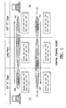
- Fig. 1 is a block diagram showing a conventional Internet asymmetric network routing model. Peering is an example of a system that leads to asymmetric data transmission (i.e., point A to point B and point B to point A traffic does not use the same path).
- a client 110 connects to an originating ISP (such as a regional ISP 130) and a client 120 connects to another originating ISP (such as regional ISP 142).
- ISPs 130 and 142 act as both originating and terminating ISPs, because their customers both send and receive data, although this may not always be the case for all ISPs.
- ISPs generally take a data packet to the closest "peering point,” transfer it to the destination ISP's network, and that ISP carries it on to the destination end-user (i.e., their customer). This is referred to as "hot potato" routing, because it effectively gets traffic off of the originating ISPs network as quickly as possible. Once traffic is off-net of the originating ISP, the originating ISP cannot assure performance.
- an ISP transfers packets off its network as quickly as possible, packets traveling between points A and B will not take the same path as packets traveling from B to A.
- ISP 142 acts as a "long-haul" ISP, transporting the data to client 120. This occurs because peering ISPs generally hand off data to a peer ISP as quickly as possible.
- ISP 142 generally uses hot potato routing.
- Fig. 1 shows a packet having a source 110 and a destination 120 as it moves through the network. As the packet physically "hops" from one router to another, each router routes the packet in accordance with the address of destination 120. The same destination address is used to route the packet throughout the network in this example.
- the method and system of the invention preferably provide a single, symmetric path for forward and return traffic between two points on the Internet.
- symmetric means that a packet between point A and point B will take the same path on the Internet as a packet between point B and point A.
- a high speed backbone also called an extranet.
- the described embodiments of the present invention aid in providing guaranteed Quality of Service (QoS) to clients, whether those clients are individual users, other carriers, or companies because the packets will take fewer hops and will be transmitted over a high quality backbone for a significant part of its journey.
- QoS Quality of Service
- the described embodiments of the present invention create a tunnel, such as a GRE tunnel, between a client's router and an edge router on the backbone.
- This process creates a logical interface on the client's router that is used to send traffic destined for other endpoints on the network.
- a destination router will have a similar tunnel established and will receive the packet through that tunnel.
- a dynamic routing protocol with policy control capability (for example, BGP-4) is created inside the tunnel in order to announce routes that are available on the network service.
- BGP-4 policy control capability
- Use of such a routing protocol creates a routing situation that allows standard best-effort traffic to flow over the customer's ISP and out to destinations on the Internet, but causes business critical traffic to flow over the backbone network to ensure delivery quality.
- the service cannot be used as a general Internet transit service. Only client destinations can be reached via the tunnels. Additionally, because a dynamic routing protocol is used for routing, if the service becomes unavailable, the destination is still reachable via the standard Internet path. This ensures that a failure in the service does not impair critical data flow.
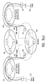
- Fig. 2 is a block diagram showing a networking model in accordance with an embodiment of the present invention. It should be noted that the network of Fig. 2 uses symmetric routing since packets sent from point A to point B take the same path through the tunnels as packets sent from point B to point A. In this model, end users A and B 210, 220 (herein called “clients) still contract with their local ISPs for service as described above. ISP 230 and ISP 250 are called "customers" of the backbone carrier 240. In certain embodiments in accordance with the system of Fig. 2, backbone 240 agrees to a Service Level Agreement (SLA) with each customer or with each client to meet certain quality requirements for delivery of this data.
- SLA Service Level Agreement
- Fig. 2 shows a simplified example of a TCP packet 260 sent between client 210 and client 220.
- the initial packet has a source field identifying client 210 and a destination field identifying client 220.
- a tunneling packet header is added to the original packet.
- the tunneling packet header identifies the source as client 210 and the destination as an edge router of backbone 240.
- the packet is then routed through the tunnel between the client's 210 router and the first edge router in accordance with its new header.
- the packet Once the packet reaches the destination edge router of backbone 240, it is recognized as a packet received through a tunnel and the tunneling packet header is stripped off, leaving the original packet header with the original packet destination (i.e., client 220). The packet is then routed according to its original header to a second edge router on backbone 240.
- the second edge router of backbone 240 recognizes that the packet is destined for a client having a tunnel. It adds a second tunneling packet header to the original packet. The second tunneling packet header identifies the source as the edge router of backbone 240 and the destination as client 220. The packet is then routed through the second tunnel between the edge router and the client's router. This process is described in more detail in connection with Figs. 3(a)-3(c) and 4(a)-4(d).
- backbone 240 has at least two edge routers 345, 347.
- Customers such as regional ISPs 230, 250, connect to backbone structure 240 via these edge routers.
- clients A and B connect to exchange sites of backbone 240 via regional networks 230 and 250 (customers) by establishing respective tunnels 302 and 304 on regional networks 230 and 250.
- the tunnel is preferably implemented using the GRE tunneling protocol as defined in at least RFC 1701, RFC 1702, and RFC 2784 (GRE over IP), which are herein incorporated by reference.
- RFCs ("Request for Comments") are documents available from the Internet Engineering Taskforce (IETF) defining various aspects of Internet design and operation.
- Fig. 3(a) also includes various routers (R) within the Internet transit system 301, various routers (R) within ISPs 230, 250, and various routers (C) within backbone 240.
- Fig. 3(b) is a block diagram showing a network having multiple customers in accordance with a preferred embodiment of the present invention.
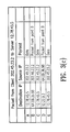
- Fig. 3(c) is a table showing destination and source addresses of a packet as it travels through the network of Fig. 3(b).
- Fig. 3(c) shows a packet at points A, B, C, D, and E as it travels from its original source client A (also called a "first client”) to its original client B(also called a "second client").
- client A having IP address 202.45.23.2 sends a packet to client B (such as a web server) having IP address 12.78.45.5.
- client B such as a web server
- the source of the packet is the original source
- client A IP address 202.45.23.2
- the destination is the original client B (IP address 12.78.45.5).
- the packet from point A receives a new tunneling-packet header specifying that the source of the packet is the client router (IP address 202.46.23.2) and the destination is an edge router 345 in the backbone (IP address 64.69.35.98).
- the routing table on the client router 350 was previously filled with routing information from its hosting edge router 345 to effect this routing in accordance with a centralized BGP-4 routing policy.
- packets to and from client A to client B will always travel to the backbone through the tunnel between the backbone 240 and client A's router 350.
- the packet may travel through one or more other networks on its way to the backbone (or it may be connected directly to the backbone).
- the packet When the packet is received at the first edge router 345 of the backbone 240, it is stripped of its packet-tunneling header, and the destination again becomes that of the original client B (IP address 12.78.45.5). Thus, within the backbone, at point C, the packet reverts to its destination of IP address 12.78.45.5 and a source of the original client (IP address 202.45.23.2).
- the packet is routed through the backbone 240 using normal routing methods.
- the routing tables of the backbone have been set to direct a packet to client B to a second edge router 347 on the backbone.
- the second edge router 347 recognizes it as a packet destined for a client who has a tunnel established.
- the second edge router gives the packet a new tunneling-packet header specifying that the source of the packet is itself (IP address 64.69.36.98) and the destination is the router of the client B (IP address 12.22.9.2).
- IP address 64.69.36.98 IP address 64.69.36.98
- the destination IP address 12.22.9.2
- packets to and from the original source, client A, to the original destination, client B will always travel to the backbone 240 through the tunnel 304 between the second edge router of the backbone and client B's router.
- client B's router 352 the tunneling header is stripped off by the router, and the packet is delivered to its destination.
- Use of a tunnel between a client and an exchange site helps ensure that the customer's data is delivered to the backbone carrier.
- the clients connect to exchange sites of the backbone 240 by establishing respective tunnels 302 and 304.
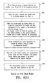
- Fig. 4(a)-4(d) are flow charts showing details of the routing method of Fig. 3.
- Fig. 4(a) shows an example of a provisioning method used to establish the tunnel between a new client and the backbone provider.
- a new client requests 402 service from the backbone provider.
- Client A is used as a new client by way of example. This request may be done by way of a telephone call or web form from a human being, or by any other appropriate method.
- the new client sends 404 the following information:
- the backbone provider configures 406 a GRE tunnel and BGP session for client A. This is done once per tunnel, since the tunnel will persist once established. A particular edge router will host the client's session. At this time, a new IP address is allocated for client A on the backbone router for the GRE tunnel end point and a new subnet is assigned to the GRE tunnel. This subnet is used for the BGP peering session between client A and the backbone router.
- the backbone provider specifies 408 policy controls on client A's BGP session to limit the BGP announcements to the set of subscribed prefixes.
- the backbone provider also sends 410 to client A the following:
- Client A configures 412 the GRE tunnel and BGP session and the client and backbone provider verify 414 operation of the tunnel.
- Client A and the backbone provider also verify 416 operation of BGP routing at this time.
- BGP sends 418 all clients the lists of subscribed prefixes.
- a client by definition, has an established tunnel to the backbone and all clients can communicate using the tunnel and backbone. (Unless, of course the backbone is unavailable, at which time the clients communicate over the regular Internet, as shown in Fig. 3(a)).
- a preferred embodiment of the present invention uses a centralized routing policy in which transmission and reception of routes to individual clients is controlled by each edge router in the backbone.
- the described embodiment uses a client-specific centralized routing policy.
- Each edge router controls what routes are accepted from each client and which routes are transmitted to each client, using the routing policy installed on the edge router at the time of provisioning.
- Each edge router inspects and then rejects or approves the subnets received from a new client. If the subnets from that client are approved, then they are forwarded to every other edge router in the backbone.
- Each client tunnel session is hosted by a specific edge router. Once the routes are received from the other edge routers, each edge router will apply the routing policies for its hosted clients to determine whether to forward the received routes to those clients.
- Fig. 4(b) shows how a PC on client A sends a packet destined for another client (client B) of the backbone provider.
- client B client of the backbone provider.
- PC PC
- the client A's router receives 422 the packet ultimately destined for client B.
- the router at client A looks up 424 the routing entry for client B's router in the routing tables of the router for client A.
- Client A's router has been configured to send the packet to the interface with the longest match.
- the longest match for client B specifies that the tunnel interface is the egress interface of client A's router.
- the packet is sent to the tunnel interface for processing.
- the tunnel subsystem on client A's router processes 426 the packet by adding a new IP header to the packet, using the rules in RFCs 1702 and 2784. This is called "encapsulating the packet.”
- Client A's router begins routing 428 the encapsulated packet using the new IP header. The longest match routing now results in the serial interface as the egress interface of the router.
- the encapsulated packet is transmitted 429 using the serial interface of the router to the ISP.
- Fig. 4(c) is a flowchart showing how a first backbone edge router, receiving 430 a packet through a tunnel from client A, routes the packet onward.
- the edge router removes 432 the packet header added by client A's router.
- the edge router uses the longest match routing algorithm on the destination of the original packet to route and send 434, 436 the packet onward through the backbone.
- the routing tables of the backbone are set to route the packets to the destination through the backbone to the second edge router.
- Fig. 4(d) shows how the second edge router of the backbone routes the packet so that it is sent through the second tunnel to a router of client B.
- the second edge router receives 440 the packet destined for client B.
- the second edge router looks up 442 the routing entry for client B in the routing tables of the edge router.
- the longest match for the second client specifies that the tunnel interface is the egress interface of the edge router.
- the packet is sent to the tunnel interface for processing.
- the tunnel subsystem on the edge router processes 444 the packet. This processing adds a new IP header to the packet, using the rules in RFCs 1702 and 2784.
- the second edge router of the backbone begins routing the encapsulated packet using the new IP header. The longest match routing results 448 in the serial interface as the egress interface of the second edge router.
- the encapsulated packet is transmitted 448 using the serial interface to the router of client B. Client B's router strips away the encapsulation and delivers the packet to client B's computer or computing device.
- a similar method is used to transmit packets from client B to client A.
- the routing method and system of the present invention creates an optimally routed network between arbitrary locations on the Internet
- the routing to and from any two given clients is symmetric because all packets between the two clients pass through a tunnel between the sending router and the backbone, and back out a tunnel between the backbone and the destination router.
- This method therefore, provides an overlay network on the Internet for the transport of premium class traffic.
- the method also provides auto learning of new subscribers by existing subscribers because the described embodiment uses the BGP routing protocol, which updates the routing tables of clients when a new client is added.
- Centralized routing policy administration allows the backbone provider to control client access. This control facilitates stability and eliminates backbone failures due to client errors.
Landscapes
- Engineering & Computer Science (AREA)
- Computer Networks & Wireless Communication (AREA)
- Signal Processing (AREA)
- Quality & Reliability (AREA)
- Data Exchanges In Wide-Area Networks (AREA)
- Monitoring And Testing Of Exchanges (AREA)
- Radio Relay Systems (AREA)
- Meter Arrangements (AREA)
- Mobile Radio Communication Systems (AREA)
- Circuits Of Receivers In General (AREA)
Claims (25)
- Procédé d'envoi d'un message sur un réseau par l'intermédiaire d'une porteuse de réseau d'infrastructure (240), comprenant les étapes consistant à :établir un premier tunnel (302) entre un premier routeur (350) d'un premier client (210) et un premier routeur de bordure (345) sur le réseau d'infrastructure (240) ;établir un second tunnel (304) entre un second routeur (352) d'un second client (220) et un second routeur de bordure (347) sur le réseau d'infrastructure (240) ;recevoir, au moyen du réseau d'infrastructure (240), un paquet .par l'intermédiaire du premier tunnel (302), à partir du premier client (210) ;acheminer les paquets par l'intermédiaire du réseau d'infrastructure (240) ; ettransmettre, au moyen du réseau d'infrastructure (240), le paquet par l'intermédiaire du second tunnel (304), au second client (220), des paquets transférés dudit premier client (210) audit second client (220) suivant le même chemin défini par le premier tunnel (302), le réseau d'infrastructure (240) et le second tunnel (304) que des paquets transférés dudit second client (220) audit premier client (210).
- Procédé selon la revendication 1, dans lequel le premier tunnel (302) est un tunnel IP dans IP.
- Procédé selon la revendication 1, dans lequel le premier tunnel (302) est un tunnel d'encapsulation de routine générique (GRE).
- Procédé selon la revendication 1 comportant en outre l'étape consistant à informer la totalité des clients lorsqu'un nouveau tunnel est créé.
- Procédé selon la revendication 1, comportant en outre l'étape consistant à envoyer un paquet par l'intermédiaire d'un mécanisme de transport de service au mieux lorsqu'un tunnel (302, 304) ou le réseau d'infrastructure (240) n'est pas disponible.
- Procédé selon la revendication 1, comportant en outre l'étape consistant à envoyer des mises à jour à la table d'acheminement du premier routeur (350) occasionnant que des paquets à envoyer à des clients soient envoyés par l'intermédiaire du tunnel.
- Procédé selon la revendication 1, comportant en outre l'étape consistant à ajouter, au moyen du premier routeur (350), un nouvel en-tête à des paquets à envoyer aux clients, indiquant que la destinataire du paquet est un routeur (345) dans le réseau d'infrastructure (240).
- Procédé selon la revendication 1, dans lequel l'acheminement des paquets par l'intermédiaire du réseau d'infrastructure (240) comporte les étapes consistant à :déterminer que le paquet a été reçu via un tunnel (302) ;extraire un en-tête de paquet de tunnel à partir du paquet ;etacheminer le paquet selon l'adresse de destination dans le paquet initial postérieurement à l'extraction de l'en-tête de paquet de tunnel.
- Procédé selon la revendication 1, dans lequel l'acheminement des paquets par l'intermédiaire du réseau d'infrastructure comporte les étapes consistant à :déterminer l'adresse de destination initiale du paquet etacheminer le paquet selon son adresse de destination initiale.
- Procédé selon la revendication 1, dans lequel l'étape d'envoi du paquet au second client (220) par l'intermédiaire du second tunnel (304) comporte les étapes consistant à :ajouter un nouvel en-tête au paquet qui indique que le paquet doit être envoyé par l'intermédiaire du second tunnel (304) ; etenvoyer le paquet au second client (220) par l'intermédiaire du second tunnel (304).
- Procédé selon la revendication 1, dans lequel chaque routeur de bordure (345, 347) est exploité selon une politique d'acheminement centralisée pour ses sessions de clients hébergés.
- Système d'envoi d'un message sur un réseau par l'intermédiaire d'une porteuse de réseau d'infrastructure (240), comportant :des moyens configurés pour établir un premier tunnel (302) entre un premier routeur (350) d'un premier client (210) et un premier routeur de bordure (345) sur le réseau d'infrastructure (240) ;des moyens configurés pour établir un second tunnel (304) entre un second routeur (352) d'un second client (220) et un second routeur de bordure (347) sur le réseau d'infrastructure (240) ;des moyens configurés pour recevoir, au moyen du réseau d'infrastructure (240), un paquet par l'intermédiaire du premier tunnel (302), à partir du premier client (210) ;des moyens configurés pour acheminer le paquet par l'intermédiaire du réseau d'infrastructure (240) ; etdes moyens configurés pour envoyer, au moyen du réseau d'infrastructure (240), le paquet par l'intermédiaire du premier tunnel (302), au second client (220), dans lequel des paquets transférés à partir dudit premier client (210) audit second client (220) suivent le même chemin défini par le premier tunnel (302), le réseau d'infrastructure (240), et le second tunnel (304) que des paquets transférés dudit second client (220) audit premier client (210).
- Système selon la revendication 12, dans lequel le premier tunnel (302) est un tunnel IP dans IP.
- Système selon la revendication 12, dans lequel le premier tunnel (302) est un tunnel d'encapsulation de routine générique (GRE).
- Système selon la revendication 12, dans lequel les moyens configurés en vue d'établir un premier tunnel (302) comportent un premier réseau de fournisseur d'accès Internet régional configuré pour établir le premier tunnel (302) entre le premier routeur de bordure (345) du réseau d'infrastructure (240) et le premier routeur (350) du premier client (210).
- Système selon la revendication 12, dans lequel les moyens configurés pour établir un second tunnel (304) comportent un second réseau de fournisseur d'accès Internet régional configuré pour établir le second tunnel (304) entre le second routeur de bordure (347) du réseau d'infrastructure (240) et le second routeur (352) du second client (220).
- Système selon la revendication 12, comportant en outre des moyens configurés pour informer la totalité des clients lorsqu'un nouveau tunnel est créé.
- Système selon la revendication 12, comportant en outre des moyens configurés pour envoyer un paquet par l'intermédiaire d'un mécanisme de transport de service au mieux lorsqu'un tunnel (302, 304) ou le réseau d'infrastructure (240) n'est pas disponible.
- Système selon la revendication 12, comportant en outre l'étape consistant à envoyer des mises à jour à la table d'acheminement du premier routeur (350) occasionnant que des paquets à envoyer à des clients soient envoyés par l'intermédiaire du tunnel (302).
- Système selon la revendication 12, comportant en outre des moyens configurés pour ajouter, au moyen du premier routeur (350), un nouvel en-tête à des paquets à envoyer à des clients, indiquant que la destination du paquet est un routeur (345) dans le réseau d'infrastructure (240).
- Système selon la revendication 12, dans lequel l'acheminement des paquets par l'intermédiaire du réseau d'infrastructure (240) comporte :des moyens configurés pour déterminer que le paquet a été reçu par l'intermédiaire d'un tunnel (302) ;des moyens configurés pour extraire un en-tête de paquet de tunnel à partir du paquet ; etdes moyens configurés pour acheminer le paquet selon l'adresse de destination dans le paquet initial postérieurement à l'extraction de l'en-tête de paquet de tunnel.
- Système selon la revendication 12, dans lequel les moyens configurés pour acheminer le paquet par l'intermédiaire du réseau d'infrastructure (240) comportent :des moyens configurés pour déterminer l'adresse de destination initiale du paquet ; etdes moyens configurés pour acheminer le paquet selon sa destination initiale.
- Système selon la revendication 12, dans lequel les moyens configurés pour envoyer le paquet au second client (220) par l'intermédiaire du second tunnel (304) comportentdes moyens configurés pour ajouter un nouvel en-tête au paquet qui indique que le paquet doit être envoyé par l'intermédiaire du second tunnel (304) ; etdes moyens configurés pour envoyer le paquet au second client (220) par l'intermédiaire du second tunnel (304).
- Système selon la revendication 12, dans lequel chaque routeur de bordure (345, 347) est exploité selon une politique d'acheminement centralisée pour ses sessions de clients hébergés.
- Produit programme informatique comportant des instructions de programme sur un support lisible par ordinateur, les instructions comportant des instructions permettant à un ordinateur d'exécuter les étapes consistant à :établir un premier tunnel (302) entre un premier routeur (350) d'un premier client (210) et un premier routeur de bordure (345) sur un réseau d'infrastructure (240) ;établir un second tunnel (304) entre un second routeur (352) d'un second client (220) et un second routeur de bordure (347) sur le réseau d'infrastructure (240) ; ettransférer des paquets entre lesdits premier et second clients (210, 220), de sorte que des paquets transférés dudit premier client (210) audit second client (220) suivent le même chemin défini par le premier tunnel (302), le réseau d'infrastructure (240) et le second tunnel (304), que des paquets transférés dudit second client (220) audit premier client (210).
Applications Claiming Priority (5)
| Application Number | Priority Date | Filing Date | Title |
|---|---|---|---|
| US20245600P | 2000-05-06 | 2000-05-06 | |
| US202456P | 2000-05-06 | ||
| US59785300A | 2000-06-20 | 2000-06-20 | |
| US597853 | 2000-06-20 | ||
| PCT/US2001/014647 WO2001086868A2 (fr) | 2000-05-06 | 2001-05-04 | Procede et systeme permettant d'envoyer des informations sur un extranet |
Publications (2)
| Publication Number | Publication Date |
|---|---|
| EP1281255A2 EP1281255A2 (fr) | 2003-02-05 |
| EP1281255B1 true EP1281255B1 (fr) | 2008-01-02 |
Family
ID=26897684
Family Applications (2)
| Application Number | Title | Priority Date | Filing Date |
|---|---|---|---|
| EP01933113A Expired - Lifetime EP1281255B1 (fr) | 2000-05-06 | 2001-05-04 | Procédé et système permettant d'envoyer des informations sur un extranet |
| EP01931048A Withdrawn EP1281256A2 (fr) | 2000-05-06 | 2001-05-04 | Procede et systeme de transmission d'informations sur un extranet |
Family Applications After (1)
| Application Number | Title | Priority Date | Filing Date |
|---|---|---|---|
| EP01931048A Withdrawn EP1281256A2 (fr) | 2000-05-06 | 2001-05-04 | Procede et systeme de transmission d'informations sur un extranet |
Country Status (9)
| Country | Link |
|---|---|
| US (1) | US6965937B2 (fr) |
| EP (2) | EP1281255B1 (fr) |
| JP (2) | JP2003533127A (fr) |
| AT (1) | ATE383015T1 (fr) |
| AU (2) | AU2001257524A1 (fr) |
| CA (2) | CA2408607C (fr) |
| DE (1) | DE60132193T2 (fr) |
| MX (2) | MXPA02010912A (fr) |
| WO (2) | WO2001086865A2 (fr) |
Families Citing this family (33)
| Publication number | Priority date | Publication date | Assignee | Title |
|---|---|---|---|---|
| US7162532B2 (en) | 1998-02-23 | 2007-01-09 | Koehler Steven M | System and method for listening to teams in a race event |
| CA2348353A1 (fr) | 2001-05-22 | 2002-11-22 | Marc Arseneau | Systeme de radiodiffusion locale |
| JP4728511B2 (ja) * | 2001-06-14 | 2011-07-20 | 古河電気工業株式会社 | データ中継方法、その装置およびその装置を用いたデータ中継システム |
| US6957274B2 (en) * | 2001-06-27 | 2005-10-18 | Microsoft Corporation | System adds additional new routes and default routes to a routing table to allow concurrent access to two different network connections |
| US7117267B2 (en) * | 2001-06-28 | 2006-10-03 | Sun Microsystems, Inc. | System and method for providing tunnel connections between entities in a messaging system |
| US6982984B1 (en) * | 2001-08-28 | 2006-01-03 | Redback Networks Inc. | Method and apparatus for virtual private networks |
| US7707307B2 (en) * | 2003-01-09 | 2010-04-27 | Cisco Technology, Inc. | Method and apparatus for constructing a backup route in a data communications network |
| US20040205159A1 (en) * | 2003-03-31 | 2004-10-14 | Johnson Teddy Christian | System and method for customer access to a server site |
| US7418519B1 (en) * | 2003-05-29 | 2008-08-26 | Nortel Networks Limited | Technique for prefix limit exchange for route advertisement |
| US7864708B1 (en) * | 2003-07-15 | 2011-01-04 | Cisco Technology, Inc. | Method and apparatus for forwarding a tunneled packet in a data communications network |
| US7487243B1 (en) * | 2003-08-29 | 2009-02-03 | Juniper Networks, Inc. | Network tunnel termination device selection using weighted load balancing |
| US7554921B2 (en) * | 2003-10-14 | 2009-06-30 | Cisco Technology, Inc. | Method and apparatus for generating routing information in a data communication network |
| US8190772B2 (en) | 2003-12-29 | 2012-05-29 | Nortel Networks Limited | Apparatus and method for layer-2 and layer-3 VPN discovery |
| US8175020B2 (en) | 2004-01-30 | 2012-05-08 | Level 3 Communications, Llc | Method for the transmission and distribution of digital television signals |
| US7730294B2 (en) * | 2004-06-04 | 2010-06-01 | Nokia Corporation | System for geographically distributed virtual routing |
| US7630298B2 (en) * | 2004-10-27 | 2009-12-08 | Cisco Technology, Inc. | Method and apparatus for forwarding data in a data communications network |
| US7715395B2 (en) * | 2004-11-24 | 2010-05-11 | Microsoft Corporation | System and method for expanding the range of a mesh network |
| US7835312B2 (en) * | 2005-07-20 | 2010-11-16 | Cisco Technology, Inc. | Method and apparatus for updating label-switched paths |
| CA2552062C (fr) * | 2005-07-22 | 2016-06-28 | 4121856 Canada Inc. | Systeme et methodes permettant d'enrichir l'experience de spectateurs assistant a un evenement sportif en direct |
| US8042140B2 (en) | 2005-07-22 | 2011-10-18 | Kangaroo Media, Inc. | Buffering content on a handheld electronic device |
| US8837275B2 (en) * | 2006-02-09 | 2014-09-16 | International Business Machines Corporation | System, method and program for re-routing internet packets |
| US20070240190A1 (en) * | 2006-04-07 | 2007-10-11 | Marc Arseneau | Method and system for enhancing the experience of a spectator attending a live sporting event |
| US7916682B2 (en) * | 2006-07-14 | 2011-03-29 | Symbol Technologies, Inc. | Wireless switch network architecture implementing layer 3 mobility domains |
| US7639648B2 (en) * | 2006-07-20 | 2009-12-29 | Symbol Technologies, Inc. | Techniques for home wireless switch redundancy and stateful switchover in a network of wireless switches supporting layer 3 mobility within a mobility domain |
| US7701845B2 (en) * | 2006-09-25 | 2010-04-20 | Cisco Technology, Inc. | Forwarding data in a data communications network |
| US20080270616A1 (en) * | 2007-04-27 | 2008-10-30 | Biscom, Inc. | System and method for electronic document delivery |
| US20080291920A1 (en) * | 2007-05-21 | 2008-11-27 | At&T Knowledge Ventures, L.P. | System and method for managing communications |
| US7940776B2 (en) * | 2007-06-13 | 2011-05-10 | Cisco Technology, Inc. | Fast re-routing in distance vector routing protocol networks |
| US20090016361A1 (en) * | 2007-07-09 | 2009-01-15 | At&T Knowledge Ventures, L.P. | System and method for establishing communications between packet-switched networks |
| CN101534240B (zh) * | 2008-03-14 | 2012-04-25 | 华为技术有限公司 | 一种映射信息的发送方法、系统和装置 |
| US9088511B2 (en) | 2012-11-19 | 2015-07-21 | Intel Corporation | Multi-hop error recovery |
| US9525627B2 (en) * | 2014-05-27 | 2016-12-20 | Google Inc. | Network packet encapsulation and routing |
| US9806985B2 (en) * | 2015-03-02 | 2017-10-31 | Cisco Technology, Inc. | Symmetric routing enforcement |
Citations (1)
| Publication number | Priority date | Publication date | Assignee | Title |
|---|---|---|---|---|
| US5325362A (en) * | 1993-09-29 | 1994-06-28 | Sun Microsystems, Inc. | Scalable and efficient intra-domain tunneling mobile-IP scheme |
Family Cites Families (11)
| Publication number | Priority date | Publication date | Assignee | Title |
|---|---|---|---|---|
| US6137791A (en) * | 1997-03-25 | 2000-10-24 | Ericsson Telefon Ab L M | Communicating packet data with a mobile station roaming within an incompatible mobile network |
| US6104716A (en) * | 1997-03-28 | 2000-08-15 | International Business Machines Corporation | Method and apparatus for lightweight secure communication tunneling over the internet |
| JP2923921B1 (ja) * | 1998-01-23 | 1999-07-26 | 日本電気株式会社 | パケット転送方式 |
| US6118785A (en) * | 1998-04-07 | 2000-09-12 | 3Com Corporation | Point-to-point protocol with a signaling channel |
| US6466985B1 (en) * | 1998-04-10 | 2002-10-15 | At&T Corp. | Method and apparatus for providing quality of service using the internet protocol |
| US6449272B1 (en) * | 1998-05-08 | 2002-09-10 | Lucent Technologies Inc. | Multi-hop point-to-point protocol |
| US6442588B1 (en) * | 1998-08-20 | 2002-08-27 | At&T Corp. | Method of administering a dynamic filtering firewall |
| US6292839B1 (en) * | 1998-12-09 | 2001-09-18 | 3Com Corporation | Method and system for reflexive tunneling |
| US6640251B1 (en) * | 1999-03-12 | 2003-10-28 | Nortel Networks Limited | Multicast-enabled address resolution protocol (ME-ARP) |
| US6473863B1 (en) * | 1999-10-28 | 2002-10-29 | International Business Machines Corporation | Automatic virtual private network internet snoop avoider |
| US6631416B2 (en) * | 2000-04-12 | 2003-10-07 | Openreach Inc. | Methods and systems for enabling a tunnel between two computers on a network |
-
2001
- 2001-05-04 EP EP01933113A patent/EP1281255B1/fr not_active Expired - Lifetime
- 2001-05-04 JP JP2001582963A patent/JP2003533127A/ja not_active Withdrawn
- 2001-05-04 MX MXPA02010912A patent/MXPA02010912A/es unknown
- 2001-05-04 AU AU2001257524A patent/AU2001257524A1/en not_active Abandoned
- 2001-05-04 WO PCT/US2001/014366 patent/WO2001086865A2/fr not_active Ceased
- 2001-05-04 AT AT01933113T patent/ATE383015T1/de not_active IP Right Cessation
- 2001-05-04 WO PCT/US2001/014647 patent/WO2001086868A2/fr not_active Ceased
- 2001-05-04 AU AU2001259562A patent/AU2001259562A1/en not_active Abandoned
- 2001-05-04 US US09/849,176 patent/US6965937B2/en not_active Expired - Lifetime
- 2001-05-04 EP EP01931048A patent/EP1281256A2/fr not_active Withdrawn
- 2001-05-04 JP JP2001582960A patent/JP2004514305A/ja not_active Withdrawn
- 2001-05-04 CA CA2408607A patent/CA2408607C/fr not_active Expired - Lifetime
- 2001-05-04 MX MXPA02010911A patent/MXPA02010911A/es active IP Right Grant
- 2001-05-04 CA CA002408603A patent/CA2408603A1/fr not_active Abandoned
- 2001-05-04 DE DE60132193T patent/DE60132193T2/de not_active Expired - Lifetime
Patent Citations (1)
| Publication number | Priority date | Publication date | Assignee | Title |
|---|---|---|---|---|
| US5325362A (en) * | 1993-09-29 | 1994-06-28 | Sun Microsystems, Inc. | Scalable and efficient intra-domain tunneling mobile-IP scheme |
Non-Patent Citations (1)
| Title |
|---|
| GILLIGAN R. ET AL: "Transition Mechanisms for IPv6 Hosts and Routers (RFC 1933)", IETF NETWORK WORKING GROUP, April 1996 (1996-04-01), pages 1 - 22, XP015007717 * |
Also Published As
| Publication number | Publication date |
|---|---|
| DE60132193T2 (de) | 2008-12-18 |
| EP1281256A2 (fr) | 2003-02-05 |
| EP1281255A2 (fr) | 2003-02-05 |
| WO2001086868A3 (fr) | 2002-05-23 |
| CA2408607C (fr) | 2010-07-06 |
| AU2001259562A1 (en) | 2001-11-20 |
| ATE383015T1 (de) | 2008-01-15 |
| WO2001086865A3 (fr) | 2002-06-06 |
| US6965937B2 (en) | 2005-11-15 |
| WO2001086865A2 (fr) | 2001-11-15 |
| MXPA02010912A (es) | 2005-06-17 |
| JP2004514305A (ja) | 2004-05-13 |
| DE60132193D1 (de) | 2008-02-14 |
| WO2001086868A2 (fr) | 2001-11-15 |
| US20020069292A1 (en) | 2002-06-06 |
| AU2001257524A1 (en) | 2001-11-20 |
| MXPA02010911A (es) | 2004-09-13 |
| JP2003533127A (ja) | 2003-11-05 |
| CA2408607A1 (fr) | 2001-11-15 |
| CA2408603A1 (fr) | 2001-11-15 |
Similar Documents
| Publication | Publication Date | Title |
|---|---|---|
| US6965937B2 (en) | Method and system for sending information on an extranet | |
| EP1678884B1 (fr) | Procedes et dispositifs servant a supporter l'acheminement d'informations | |
| US6678264B1 (en) | Establishing connections with a pre-specified quality of service across a communication network | |
| US6810417B2 (en) | Content delivery network system and method for network configuring | |
| US6680943B1 (en) | Establishing bi-directional communication sessions across a communications network | |
| JP4448040B2 (ja) | 既存のリザーベーションプロトコルおよびフレームフォーマットを使用してネットワーク内およびネットワークを横切って行われる保証されたサービスの品質またはクラスを提供する方法および装置 | |
| US6963575B1 (en) | Enhanced data switching/routing for multi-regional IP over fiber network | |
| US6829221B1 (en) | Border gateway protocol manager and method of managing the selection of communication links | |
| EP1069742B1 (fr) | Procédé et architecture permettant des service multiples dans un réseau à commutation d' étiquette | |
| EP0935373A2 (fr) | Système permettant d'améliorer la qualité de service pour les connections d' un réseau longue distance | |
| US20050078668A1 (en) | Network element having a redirect server | |
| US20150146573A1 (en) | Apparatus and method for layer-2 and layer-3 vpn discovery | |
| JP4880698B2 (ja) | ビッド・ネットワーク | |
| US20070133570A1 (en) | System and/or method for bidding | |
| EP1043869A2 (fr) | Fourniture de qualité de service dans des réseaux L2TP (Layer Two Tunneling Protocol) | |
| Quoitin et al. | Using redistribution communities for interdomain traffic engineering | |
| JP4881392B2 (ja) | ダウンストリーム・ビッドのためのシステムおよび/または方法 | |
| US20070130046A1 (en) | Quality of service for transmission of digital content | |
| Murhammer et al. | IP Network Design Guide | |
| Kim et al. | Scalable IPv6 multi-homing scheme based on end-to-end argument | |
| US20060227772A1 (en) | Method and system for packet data communication between networks | |
| ALGhamdi | Virtual Private Networks |
Legal Events
| Date | Code | Title | Description |
|---|---|---|---|
| PUAI | Public reference made under article 153(3) epc to a published international application that has entered the european phase |
Free format text: ORIGINAL CODE: 0009012 |
|
| 17P | Request for examination filed |
Effective date: 20021125 |
|
| AK | Designated contracting states |
Designated state(s): AT BE CH CY DE DK ES FI FR GB GR IE IT LI LU MC NL PT SE TR |
|
| AX | Request for extension of the european patent |
Extension state: AL LT LV MK RO SI |
|
| RAP1 | Party data changed (applicant data changed or rights of an application transferred) |
Owner name: WILLIAMS COMMUNICATIONS, LLC |
|
| RAP1 | Party data changed (applicant data changed or rights of an application transferred) |
Owner name: WILTEL COMMUNICATIONS GROUP, INC. |
|
| 17Q | First examination report despatched |
Effective date: 20040920 |
|
| RAP1 | Party data changed (applicant data changed or rights of an application transferred) |
Owner name: WILTEL COMMUNICATIONS GROUP, LLC |
|
| 17Q | First examination report despatched |
Effective date: 20040920 |
|
| GRAP | Despatch of communication of intention to grant a patent |
Free format text: ORIGINAL CODE: EPIDOSNIGR1 |
|
| RIC1 | Information provided on ipc code assigned before grant |
Ipc: H04L 12/56 20060101AFI20070702BHEP Ipc: H04L 29/06 20060101ALI20070702BHEP Ipc: H04L 12/46 20060101ALI20070702BHEP |
|
| RTI1 | Title (correction) |
Free format text: METHOD AND SYSTEM FOR SENDING INFORMATION ON AN EXTRANET |
|
| GRAS | Grant fee paid |
Free format text: ORIGINAL CODE: EPIDOSNIGR3 |
|
| GRAA | (expected) grant |
Free format text: ORIGINAL CODE: 0009210 |
|
| RAP1 | Party data changed (applicant data changed or rights of an application transferred) |
Owner name: LEVEL 3 COMMUNICATIONS, LLC |
|
| AK | Designated contracting states |
Kind code of ref document: B1 Designated state(s): AT BE CH CY DE DK ES FI FR GB GR IE IT LI LU MC NL PT SE TR |
|
| AX | Request for extension of the european patent |
Extension state: AL LT LV MK RO SI |
|
| REG | Reference to a national code |
Ref country code: GB Ref legal event code: FG4D |
|
| REG | Reference to a national code |
Ref country code: IE Ref legal event code: FG4D |
|
| REG | Reference to a national code |
Ref country code: CH Ref legal event code: EP |
|
| REF | Corresponds to: |
Ref document number: 60132193 Country of ref document: DE Date of ref document: 20080214 Kind code of ref document: P |
|
| PG25 | Lapsed in a contracting state [announced via postgrant information from national office to epo] |
Ref country code: NL Free format text: LAPSE BECAUSE OF FAILURE TO SUBMIT A TRANSLATION OF THE DESCRIPTION OR TO PAY THE FEE WITHIN THE PRESCRIBED TIME-LIMIT Effective date: 20080102 |
|
| NLV1 | Nl: lapsed or annulled due to failure to fulfill the requirements of art. 29p and 29m of the patents act | ||
| PG25 | Lapsed in a contracting state [announced via postgrant information from national office to epo] |
Ref country code: LI Free format text: LAPSE BECAUSE OF FAILURE TO SUBMIT A TRANSLATION OF THE DESCRIPTION OR TO PAY THE FEE WITHIN THE PRESCRIBED TIME-LIMIT Effective date: 20080102 Ref country code: CH Free format text: LAPSE BECAUSE OF FAILURE TO SUBMIT A TRANSLATION OF THE DESCRIPTION OR TO PAY THE FEE WITHIN THE PRESCRIBED TIME-LIMIT Effective date: 20080102 Ref country code: ES Free format text: LAPSE BECAUSE OF FAILURE TO SUBMIT A TRANSLATION OF THE DESCRIPTION OR TO PAY THE FEE WITHIN THE PRESCRIBED TIME-LIMIT Effective date: 20080413 Ref country code: FI Free format text: LAPSE BECAUSE OF FAILURE TO SUBMIT A TRANSLATION OF THE DESCRIPTION OR TO PAY THE FEE WITHIN THE PRESCRIBED TIME-LIMIT Effective date: 20080102 |
|
| REG | Reference to a national code |
Ref country code: CH Ref legal event code: PL |
|
| PG25 | Lapsed in a contracting state [announced via postgrant information from national office to epo] |
Ref country code: AT Free format text: LAPSE BECAUSE OF FAILURE TO SUBMIT A TRANSLATION OF THE DESCRIPTION OR TO PAY THE FEE WITHIN THE PRESCRIBED TIME-LIMIT Effective date: 20080102 |
|
| PG25 | Lapsed in a contracting state [announced via postgrant information from national office to epo] |
Ref country code: PT Free format text: LAPSE BECAUSE OF FAILURE TO SUBMIT A TRANSLATION OF THE DESCRIPTION OR TO PAY THE FEE WITHIN THE PRESCRIBED TIME-LIMIT Effective date: 20080602 Ref country code: BE Free format text: LAPSE BECAUSE OF FAILURE TO SUBMIT A TRANSLATION OF THE DESCRIPTION OR TO PAY THE FEE WITHIN THE PRESCRIBED TIME-LIMIT Effective date: 20080102 |
|
| EN | Fr: translation not filed | ||
| PG25 | Lapsed in a contracting state [announced via postgrant information from national office to epo] |
Ref country code: DK Free format text: LAPSE BECAUSE OF FAILURE TO SUBMIT A TRANSLATION OF THE DESCRIPTION OR TO PAY THE FEE WITHIN THE PRESCRIBED TIME-LIMIT Effective date: 20080102 Ref country code: SE Free format text: LAPSE BECAUSE OF FAILURE TO SUBMIT A TRANSLATION OF THE DESCRIPTION OR TO PAY THE FEE WITHIN THE PRESCRIBED TIME-LIMIT Effective date: 20080402 |
|
| PLBE | No opposition filed within time limit |
Free format text: ORIGINAL CODE: 0009261 |
|
| STAA | Information on the status of an ep patent application or granted ep patent |
Free format text: STATUS: NO OPPOSITION FILED WITHIN TIME LIMIT |
|
| 26N | No opposition filed |
Effective date: 20081003 |
|
| PG25 | Lapsed in a contracting state [announced via postgrant information from national office to epo] |
Ref country code: MC Free format text: LAPSE BECAUSE OF NON-PAYMENT OF DUE FEES Effective date: 20080531 |
|
| PG25 | Lapsed in a contracting state [announced via postgrant information from national office to epo] |
Ref country code: FR Free format text: LAPSE BECAUSE OF FAILURE TO SUBMIT A TRANSLATION OF THE DESCRIPTION OR TO PAY THE FEE WITHIN THE PRESCRIBED TIME-LIMIT Effective date: 20081024 Ref country code: IE Free format text: LAPSE BECAUSE OF NON-PAYMENT OF DUE FEES Effective date: 20080505 |
|
| PG25 | Lapsed in a contracting state [announced via postgrant information from national office to epo] |
Ref country code: CY Free format text: LAPSE BECAUSE OF FAILURE TO SUBMIT A TRANSLATION OF THE DESCRIPTION OR TO PAY THE FEE WITHIN THE PRESCRIBED TIME-LIMIT Effective date: 20080102 |
|
| PG25 | Lapsed in a contracting state [announced via postgrant information from national office to epo] |
Ref country code: IT Free format text: LAPSE BECAUSE OF FAILURE TO SUBMIT A TRANSLATION OF THE DESCRIPTION OR TO PAY THE FEE WITHIN THE PRESCRIBED TIME-LIMIT Effective date: 20080102 |
|
| PG25 | Lapsed in a contracting state [announced via postgrant information from national office to epo] |
Ref country code: LU Free format text: LAPSE BECAUSE OF NON-PAYMENT OF DUE FEES Effective date: 20080504 |
|
| PG25 | Lapsed in a contracting state [announced via postgrant information from national office to epo] |
Ref country code: TR Free format text: LAPSE BECAUSE OF FAILURE TO SUBMIT A TRANSLATION OF THE DESCRIPTION OR TO PAY THE FEE WITHIN THE PRESCRIBED TIME-LIMIT Effective date: 20080102 |
|
| PG25 | Lapsed in a contracting state [announced via postgrant information from national office to epo] |
Ref country code: GR Free format text: LAPSE BECAUSE OF FAILURE TO SUBMIT A TRANSLATION OF THE DESCRIPTION OR TO PAY THE FEE WITHIN THE PRESCRIBED TIME-LIMIT Effective date: 20080403 |
|
| PGFP | Annual fee paid to national office [announced via postgrant information from national office to epo] |
Ref country code: DE Payment date: 20200422 Year of fee payment: 20 |
|
| PGFP | Annual fee paid to national office [announced via postgrant information from national office to epo] |
Ref country code: GB Payment date: 20200422 Year of fee payment: 20 |
|
| REG | Reference to a national code |
Ref country code: DE Ref legal event code: R071 Ref document number: 60132193 Country of ref document: DE |
|
| REG | Reference to a national code |
Ref country code: GB Ref legal event code: PE20 Expiry date: 20210503 |
|
| PG25 | Lapsed in a contracting state [announced via postgrant information from national office to epo] |
Ref country code: GB Free format text: LAPSE BECAUSE OF EXPIRATION OF PROTECTION Effective date: 20210503 |