EP1281344A2 - Garniture de balai laveur et système d'essuyage comprenant une garniture de balai laveur et un cadre tendeur - Google Patents
Garniture de balai laveur et système d'essuyage comprenant une garniture de balai laveur et un cadre tendeur Download PDFInfo
- Publication number
- EP1281344A2 EP1281344A2 EP02405664A EP02405664A EP1281344A2 EP 1281344 A2 EP1281344 A2 EP 1281344A2 EP 02405664 A EP02405664 A EP 02405664A EP 02405664 A EP02405664 A EP 02405664A EP 1281344 A2 EP1281344 A2 EP 1281344A2
- Authority
- EP
- European Patent Office
- Prior art keywords
- mop cover
- band
- frame
- mop
- tenter
- Prior art date
- Legal status (The legal status is an assumption and is not a legal conclusion. Google has not performed a legal analysis and makes no representation as to the accuracy of the status listed.)
- Withdrawn
Links
Images


Classifications
-
- A—HUMAN NECESSITIES
- A47—FURNITURE; DOMESTIC ARTICLES OR APPLIANCES; COFFEE MILLS; SPICE MILLS; SUCTION CLEANERS IN GENERAL
- A47L—DOMESTIC WASHING OR CLEANING; SUCTION CLEANERS IN GENERAL
- A47L13/00—Implements for cleaning floors, carpets, furniture, walls, or wall coverings
- A47L13/10—Scrubbing; Scouring; Cleaning; Polishing
- A47L13/20—Mops
- A47L13/24—Frames for mops; Mop heads
- A47L13/254—Plate frames
- A47L13/258—Plate frames of adjustable or foldable type
-
- A—HUMAN NECESSITIES
- A47—FURNITURE; DOMESTIC ARTICLES OR APPLIANCES; COFFEE MILLS; SPICE MILLS; SUCTION CLEANERS IN GENERAL
- A47L—DOMESTIC WASHING OR CLEANING; SUCTION CLEANERS IN GENERAL
- A47L13/00—Implements for cleaning floors, carpets, furniture, walls, or wall coverings
- A47L13/10—Scrubbing; Scouring; Cleaning; Polishing
- A47L13/20—Mops
Definitions
- the invention relates to a mop cover according to the preamble of claim 1 and a Wiping system according to the preamble of claim 14.
- Mop covers for use with a stenter have been known for a long time.
- Such Mop covers have a holder on the back, in which a clamping frame can intervene.
- the mop cover is stretched onto the tenter frame.
- the holder is usually formed by two mutually oriented and in Pockets spaced apart.
- the tenter in turn usually exists from two pivotally connected frame parts or wings, the Ends can be inserted into the pockets.
- the two inserted into the pockets Frame parts can be spread apart and fixed in the flat position become.
- the mop cover stretched on the clamping frame can be used to damp or dry floor cleaning can be used.
- Mop covers with which the floor is cleaned with a damp cloth, have to be changed from time to time are moistened and freed of adhering dirt. For this, the mop cover is in swirled and wrung out in a wash bucket filled with water. Known Mop covers must be removed from the stenter to wring them out. This is cumbersome and time consuming.
- DE-A-40 22 36 discloses a mop cover with two opposite one another Bags into which the ends of a collapsible mop holder can be inserted.
- a tab is attached to the inside of the bag on only one side.
- At the top of the Two straps are formed with ring-shaped eyelets. The straps with the eyelets can be attached to the end thickening of the transverse axis of the mop holder become. If the mop holder spanning the mop cover is folded up, so the mop cover still hangs on one narrow side of the mop holder and can be used raised, rinsed in a bucket and wrung out in a vertical press become.
- EP-A-0 111 820 shows a mop cover which has detachable fastening means having.
- the fasteners are formed by a tab with push buttons, which can be placed around a strap of the mop holder.
- the Fasteners allow the mop cover to hang freely from a press or a Keep container with cleaning liquid.
- a disadvantage of the known mop covers is that they are when folded Hang the mop holder swinging freely on one narrow side. Free swinging mop covers cannot be easily inserted into a bucket or press. Another disadvantage is that the mop holder - due to the length of the stretched mop cover - is wide must be raised so that the mop cover does not touch the floor.
- the object of the present invention is to provide a mop cover which can easily be wrung out.
- the mop cover should also be designed that he no longer has to be held in his hands to wring it out.
- Another one The aim is to provide a wiping system consisting of a wiping cover and stenter frame enables a quick installation of the mop cover on the stenter frame.
- Another goal is to provide a tenter or mop cover holder with which a Mop cover quickly and conveniently.
- connection and Spacer for releasable and spaced connection of the mop cover at least two places with the pivotable clamping frame parts one Tenter frames are provided.
- the connection and spacing means are preferably in the area of the bags provided on the narrow sides of the mop cover or fixable.
- This new type of mop cover has the advantage that it can also be opened of the tenter via the connecting and spacing means on at least two in Places spaced from each other remains connected to the tenter.
- This has the advantage that the mop cover is folded at the same time when it is lifted.
- the raised mop cover hangs folded up on the tenter frame and can be used e.g.
- connection and Distance means at least one band, a cord or the like.
- the tape resp. the Cord means, e.g. have a hook, carabiner or the like, so the mop cover can be coupled to the tenter frame parts.
- this is at least one band or the at least one cord, in particular symmetrically with respect to a central plane, arranged on the back that the mop cover when lifting with the stenter approximately in the middle collapses. This allows effective wringing out in a suitable press.
- connection and spacing means are advantageously designed in this way and with the Tenter connectable that the tenter at least partially can be folded without the mop cover being folded. So there is preferably only a loose connection via flexible connection and spacing means between the mop cover and the stenter. Conveniently they have Connection and distance means such a length that the raised mop cover too the folded stenter ends is spaced. This is important otherwise there is a risk that the clamping frame parts when pressing the Mop covers are also recorded by the press.
- the tape or cord is advantageously detachable on the back of the mop cover arranged.
- This can be achieved, for example, in that the one end of the Bands fixed, e.g. is secured by a seam and the other second end is detachable, e.g. can be fastened by means of a Velcro fastener or other known connecting means is.
- the band preferably consists of two band sections, the first ends of the Band sections on the back of the mop cover, especially at a distance from the short side edges, are fixed and a detachable closure, e.g. Velcro fastener, for connecting the second ends of the two band sections is provided.
- a detachable closure e.g. Velcro fastener
- the length of the band respectively. the two band sections longer than the distance between the joints of the first tape ends with the back of the flat mop cover. Accordingly, it can Band resp. the interconnected band sections form a loose loop.
- the Connection and spacing means have at least such a length that the to Wring out raised mop cover is spaced from the open stenter.
- the raised mop cover is preferably more than 1 cm and preferably more than 5 Centimeters from the stenter ends. But it can also be more than 10 cm, for example, be suspended 30 cm from the stenter.
- Additional detachable fastening means can expediently be provided for Attachment of the tape respectively. the tape sections on the back of the mop cover. This has the advantage that the band can be fixed to the mop cover if it is not should be used.
- the first ends of the band are advantageously fixed in the area of the pockets on the back.
- the strap ends can also be used to attach the pockets be sewn to the back.
- the additional tape parts can be attached without significant additional manufacturing effort. Expediently are at a distance from the longitudinal edges on the back of the Mop cover longitudinal beads are provided, which act as guides for the stenter can serve. If the wrung-out mop cover is placed on the floor, you need just make sure that the free ends of the clamping frame parts inside the longitudinal beads come to rest. When unfolded, the remains Tensioning frame guided through the longitudinal beads between the longitudinal beads. That’s it Inserting the tenter into the pockets covering the longitudinal beads is essential facilitated.
- the present invention also relates to a wiping system with a wiping cover according to one of claims 1 to 14 and a stenter with at least two mutually pivotally connected clamping frame parts for clamping the Mop cover and a swivel mount provided on the stenter for attaching a stem.
- the distal ends of the clamping frame parts in the collapsed are advantageous State symmetrically arranged with respect to an imaginary central plane.
- This has the Advantage that the ends of the clamping frame parts open when the clamping frame is raised are at the same height (horizontal), and the mop cover is even on Stenter hangs.
- both short longitudinal edges of the Tension frame parts on the mop cover evenly when the tension frame is open the mop cover is removed.
- the pivot axis of the interconnected tenter frame parts runs approximately in the middle. This has the advantage that the mop cover when lifting by means of the The stretcher folds the hinges in the middle, causing a wringing out a press relieved.
- the stenter has one formed from a strong wire Frame. This is an inexpensive construction. However, it is also conceivable to have one To manufacture stenter from plastic. to use. It is preferable to the opposite ends of the tenter provided a guide for the tape. This has the advantage that the tape is not loose and is annoying when cleaning.
- the guide is expediently a slot which is separated by a strut arranged on the narrow side of the frame.
- the tape is particularly preferred passed through the slot from below. This has the advantage that when the Mop the narrow edges of the tenter frame on the belt and this when unfolding the tensioning frame parts to form a loop stretch. It is conceivable to provide several slots through which the tape loops can be. If two slots are used, the band sections can be under the stenter are connected to each other.
- the tape advantageously consists of two tape sections of approximately the same length and the Closure is a Velcro.
- the Velcro fastener is on each other adjacent second band ends provided. Because the Velcro fastener is stiffened Point of the belt, it does not slide over the bracket when lifting the mop cover of the stenter and remains in the middle. This always causes the mop cover collapses in the middle and evenly on the collapsed stenter is hung.
- the narrow Tenter frame rolling means may be provided.
- the rolling stock has the purpose of Folding apart and inserting the tenter into the pockets easier.
- the frame can be narrow A tubular sleeve must be placed on the clamping frame side. Thanks to the rotatable tube sleeve you can the stenter parts on the belt resp. Roll off the mop cover. It is conceivable especially with plastic versions of the stenter, instead of a tubular sleeve to provide one or more roles. The roles can be by means of Dovetail connections can be plugged together.
- Longitudinal beads are provided, which serve as positive guides for the stenter can.
- the positive guides allow the stenter to be in the pockets to introduce without having to bend down.
- the present invention also relates to a tenter frame for a mop cover with two clamping frame parts which can be pivoted relative to one another and which extend from one unfolded, extended position, in which a mop cover through the ends the clamping frame parts are clamped in a folded position are pivotable, characterized in that at the ends of the clamping frame parts Roll means are provided.
- the rolling means have the advantage that the clamping frame parts only with little rolling resistance in the opposite pockets of one Mop covers are insertable. In contrast, it works with the known Tensioning frame between the ends of the tensioning frame parts and the Mop cover surface a friction resistance, which the insertion of the Tension frame ends in the pockets of the mop cover much more difficult. Further Advantages of the tenter frame according to the invention are in the dependent Device claims defined.
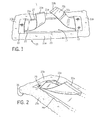
- Figures 1 to 3 show a mop cover 11 according to the invention, which for Use on a clamping frame 13 can be clamped ( Figures 4 to 6).
- the mop cover 11 has a cleaning side 15 facing the surface to be cleaned and one of the The cleaning side 15 is facing away from the rear side 17 pockets 19 arranged from one another are provided, which accommodate the reception of the Serve frame 13.
- the mop cover 11 With the help of a arranged on the back 17, from the In both belt sections 21a and 21b of existing belt 21, the mop cover 11 is detachable can be connected or coupled to the tenter frame 13.
- the mop cover 11 thus remains with the Tenter connected, and can be lifted with this ( Figure 6). This enables the mop cover to be inserted into a press and wrung out without it would have to be taken into your hands.
- the mop cover 11 is made of a cleaning textile, not shown in detail, which has a trim of cleaning fibers or threads 23 on one side.
- the Cleaning threads 23 preferably consist of a large number of microfibers Thickness of at most 30 dtex, preferably less than 20 dtex and particularly preferred less than 10 dtex. Microfibers have the advantage of being contaminated with them Surfaces cleaned mechanically and without the use of chemical agents can be.
- the mop cover 11 has an edge 25 on the back 17, which also has Cleaning fibers 23 is occupied.
- 25a is the edge of the broadside
- 25b the Inscribed on the edge of the narrow side of the mop cover.
- the edges 25a, 25b can by single or double folding of the one-sided with cleaning fibers Cleaning textile and sewing it with the back.
- a longitudinal bead 27 is formed on the edge 25a of the broad side. This Longitudinal bead 27 can be produced by appropriately sewing the folded over Cleaning textile and edging the formed bead with a textile strip.
- the pockets 19 adjoin the edges 25a, 25b of the narrow sides. You are educated by a preferably reinforced plastic band, which is over the other opposite longitudinal beads 27 and below the folded edges 25a, 25b extends. Seams 29a, 29b, not shown, which run parallel to the edges connect the folded edges 25a, 25b and the pockets 19 to the back 17 of the Mop cover 11.
- the belt 21 consists of the belt sections 21a and 21b, which have a first end are fixed on the back 17 of the mop cover.
- the Band sections 21a, 21b between the longitudinal beads 27 and in the pockets 19. They are preferably attached to the bottom of the bag.
- the first ends of the band sections 21a, 21b can also with the seams 29b with the back 17 of the mop cover be connected.
- Detachable fastening means 33 are provided, with which the band sections 21a, 21b can be detached are interconnectable.
- the closure means 33 are preferably a textile Surface fastener, e.g. a Velcro with hooks that work together 33a and stitches 33b.
- a second Velcro fastener 33c may be provided on the belt section 21b. Act the cooperating adhesive portions 33a and 33c together, so the Band sections close to the back 17. It is conceivable that the top of the Band section 21b has meshes of a Velcro fastener over the entire surface, so that section 33a can be ascertained at any point on band section 21b. Are the Band sections 21a, 21b placed around the tenter frame 13, so the mop cover 11 remains with the tenter frame 13 connected to the latter.
- the two Belt sections can be connected to each other or independently of each other band section on the stenter, e.g. on a strut provided on the bracket, be fixable.
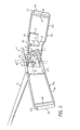
- the tenter frame 11 has two hinged wings or Frame parts 35a and 35b.
- a frame part 35a On a frame part 35a is a receptacle 37 for a handle 39 provided.
- the receptacle 37 is in the middle section of an S-shaped, in Longitudinal direction of the tenter frame 11 extending axis 41 pivotable arranged.
- the pivot axis 43 running through the central section thus runs essentially transverse to the longitudinal extension of the tenter 11.
- the axis 41 in turn is free from the frame part 35a upwardly projecting webs 45 about an axis of rotation 48 rotatably mounted. Due to this construction, the stem 39 is free on all sides flexible, which allows the greatest freedom in floor cleaning.
- the webs 45 are formed on a base plate 47, on which a first U-shaped one Bracket 49a of the first frame part 35a is fixed. Another U-shaped Bracket 49b is on the underside of the base plate 47 in the middle of the flat stenter hinged.
- a mounting plate 52 arranged on the bracket 49b one is upward protruding metal spring 51 arranged so that the terminal edge 53 of the base plate 47b can snap into a bulge in the spring 51.
- the metal spring 51 has one flat pawl 55, which can be operated with one foot. The pawl 55 is down pressed, the two frame parts can be pivoted and out of the pockets 19 withdrawn ( Figures 4 and 6).
- Struts 59 are spaced apart from the base sections 57a, 57b of the brackets 49a, 49b intended.
- the struts 59 together with the base portions 57a, 57b define one Passage or slot 61 through which the belt sections 21a and 21b are guided can be.
- the band 31, respectively. are the band sections 21a, 21b longer than the distance between those at the rear of the flat mop cover set first ends. To open the mop cover 11 the band sections 21a, 21b from below or from above through the slits 61 guided and the ends of which are releasably connected to the Velcro fastener (FIG. 4).
- bracket 49a, 49b these are first on the back 17 between the Longitudinal beads 27 supported and then spread apart. If the tape sections 49a, 49b are guided through the slots from below, the base sections 57a, 57b rest volume 21. When the frame parts 35a, 35b are spread apart, the band 21 folded and stretched in the area of the pockets. The band 21 is therefore not loose, but substantially stretched when the tenter 13 is inserted into the pockets 19.
- a tubular sleeve 63 is provided.
- the tubular sleeve 63 is freely rotatable so that the brackets 49a, 49b for insertion into the pockets 29 on the belt 21 can roll.
- rollers can also be provided. these can for example made of plastic and clipped together.
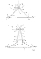
- the second exemplary embodiment of a clamping frame 11a according to FIGS. 7 to 10 has a holding plate 65, on which two clamping frame parts 66a, 66b are articulated.
- the tenter frame parts 66a, 66b are spaced apart by two Swivel axes 67a, 67b pivotable.
- On the holding plate 65 is a receptacle 37 for a stem not shown in the figures.
- the receptacle 37 is by means of a universal joint 69 connected to the holding plate 65.
- Detachable locking means serve the clamping frame parts 66a, 66b in the stretched state with the holding plate 65 to connect.
- the locking means can, for example, by means of a Spring biased latch 72 or locking bolt formed on the Holding plate 65 received in guides, not shown, and relative to Holding plate 65 is slidable.
- tenter frame parts 66a, 66b provided after Protrusions 73 projecting from above with undercuts 75 act with the latch 72 stretched frame parts 66a, 66b together and place the frame parts 66a, 66b to the holding plate 65.
- a movable actuator 71 acts with the bolt 72 together and pushes it against actuation against a spring preload a locking position in a release position.
- the rolling means 77 are preferably two at a distance from one another arranged rollers, which in a recess 79 in the clamping frame parts 66a, 66b are rotatably arranged.
- the rollers 77 are not in the recesses 79 by means of a Axles shown in more detail rotatably mounted.
- ears 81 are formed at the proximal end of the stenter parts 66a, 66b.
- the ears 81 have a round hole 83 for receiving a further axis for the articulated connection of the clamping frame parts 66a, 66b with the Holding plate 65.
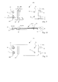
- Recess 84 is provided, which through a roller 87 in two slots 85a and 85b is divided. Through the slots 85a, 85b, the band 21 can be used to connect the Mop cover 11 are looped to the tenter frame 11a. As from FIGS. 7 and 8 can be seen, the clamping frame 11a is symmetrical with respect to a central plane 86. As a result, the mop cover, when the stenter is released and if this is raised, automatically folded in the middle.
- the exemplary embodiment according to FIG. 11 differs from the example according to FIGS 9 and 10 in that no roller 87 is provided in the recess 84. Accordingly, the band sections 21a, 21b from above, respectively. outside through the Recesses 84 guided and releasably connected to each other (see. Fig. 8).
- a mop cover for a collapsible stenter 13 has one Cleaning fibers, threads or the like having cleaning side 15 and one of the Cleaning side 15 facing away from the back 17 with two spaced apart arranged and mutually oriented pockets 19.
- the pockets 19 serve the Inclusion of a clamping frame 13.
- Connecting and spacing means 21 preferably a flexible band or cord, for detachable and spaced connection of the mop cover to the tensioning frame 13 intended.
Landscapes
- Cleaning Implements For Floors, Carpets, Furniture, Walls, And The Like (AREA)
Applications Claiming Priority (2)
| Application Number | Priority Date | Filing Date | Title |
|---|---|---|---|
| CH14142001 | 2001-07-30 | ||
| CH14142001 | 2001-07-30 |
Publications (2)
| Publication Number | Publication Date |
|---|---|
| EP1281344A2 true EP1281344A2 (fr) | 2003-02-05 |
| EP1281344A3 EP1281344A3 (fr) | 2004-11-03 |
Family
ID=4565456
Family Applications (1)
| Application Number | Title | Priority Date | Filing Date |
|---|---|---|---|
| EP02405664A Withdrawn EP1281344A3 (fr) | 2001-07-30 | 2002-07-30 | Garniture de balai laveur et système d'essuyage comprenant une garniture de balai laveur et un cadre tendeur |
Country Status (1)
| Country | Link |
|---|---|
| EP (1) | EP1281344A3 (fr) |
Cited By (4)
| Publication number | Priority date | Publication date | Assignee | Title |
|---|---|---|---|---|
| WO2006027046A1 (fr) * | 2004-09-03 | 2006-03-16 | Carl Freudenberg Kg | Garniture de recurage |
| CN103417169A (zh) * | 2012-05-24 | 2013-12-04 | 张强 | 多功能地板清洁装置 |
| US10028634B1 (en) * | 2013-07-25 | 2018-07-24 | Carl Freudenberg Kg | Cleaning device, cloth and holder |
| WO2019073250A1 (fr) * | 2017-10-13 | 2019-04-18 | Scot Young Research Limited | Tête de dispositif de nettoyage |
Family Cites Families (5)
| Publication number | Priority date | Publication date | Assignee | Title |
|---|---|---|---|---|
| US1178069A (en) * | 1915-10-18 | 1916-04-04 | Alexander Wink Grant | Mop. |
| DE7733101U1 (de) * | 1977-10-27 | 1978-04-13 | Ibing Krankenhaus-Hygiene-Service Gmbh & Co Kg, 4630 Bochum | Reinigungsgeraet |
| DE3246161A1 (de) * | 1982-12-14 | 1984-06-14 | Vereinigte Mop-Werke Salmon-Ostermann Gmbh & Co Kg, 6980 Wertheim | Mopbezug |
| GB2190833B (en) * | 1986-05-28 | 1989-12-28 | Scot Young Serv Syst Ltd | Sweep mops |
| DE4022326C2 (de) * | 1990-07-13 | 1996-09-12 | Henkel Kgaa | Vorrichtung für das Naß- oder Feuchtwischen von Fußböden |
-
2002
- 2002-07-30 EP EP02405664A patent/EP1281344A3/fr not_active Withdrawn
Cited By (4)
| Publication number | Priority date | Publication date | Assignee | Title |
|---|---|---|---|---|
| WO2006027046A1 (fr) * | 2004-09-03 | 2006-03-16 | Carl Freudenberg Kg | Garniture de recurage |
| CN103417169A (zh) * | 2012-05-24 | 2013-12-04 | 张强 | 多功能地板清洁装置 |
| US10028634B1 (en) * | 2013-07-25 | 2018-07-24 | Carl Freudenberg Kg | Cleaning device, cloth and holder |
| WO2019073250A1 (fr) * | 2017-10-13 | 2019-04-18 | Scot Young Research Limited | Tête de dispositif de nettoyage |
Also Published As
| Publication number | Publication date |
|---|---|
| EP1281344A3 (fr) | 2004-11-03 |
Similar Documents
| Publication | Publication Date | Title |
|---|---|---|
| EP0500581B1 (fr) | Garniture de balai-serpilliere avec poche et rabat | |
| EP2353904B1 (fr) | Bâche latérale déplaçable pour un camion de transport | |
| DE19724457A1 (de) | Vorrichtung zum Befestigen eines Gegenstandes an Gepäckstücken | |
| CH621931A5 (fr) | ||
| DE69818019T2 (de) | Klappbarer mop | |
| EP0111820A2 (fr) | Garniture de balai | |
| EP1281344A2 (fr) | Garniture de balai laveur et système d'essuyage comprenant une garniture de balai laveur et un cadre tendeur | |
| DE3505973A1 (de) | Reinigungsgeraet fuer fussboeden o.dgl. | |
| DE4022326C2 (de) | Vorrichtung für das Naß- oder Feuchtwischen von Fußböden | |
| DE2850036A1 (de) | Drapierfalthaken fuer gardinen | |
| EP0282957B1 (fr) | Rideau plissé | |
| DE60312939T2 (de) | Abdeckungselement für Behälter oder dergleichen | |
| DE2746344A1 (de) | Faltbett | |
| DE4141803C2 (de) | Wäscheschirm mit Schutzmantel | |
| DE10310320B4 (de) | Reinigungsvorrichtung | |
| DE19805953B4 (de) | Wischtuch für einen Fußbodenwischer | |
| DE4418468C1 (de) | Textilbespannung für Feuchtreinigungsgeräte | |
| DE4439363A1 (de) | Textilbespannung für Bodenreinigungsgeräte | |
| DE20215699U1 (de) | Tragegurt, insbesondere für Fenster und Fensterrahmen | |
| DE10360755B4 (de) | Reinigungsgerät | |
| DE2358144C2 (de) | Trag- und zusammenlegbarer Wäschetrockner | |
| DE2246237C3 (de) | Verkürzbarer Schirm | |
| DE3320033C2 (fr) | ||
| DE8104134U1 (de) | Vorrichtung zum aufhaengen von gardinen | |
| WO2002076786A1 (fr) | Dispositif permettant de ranger des objets dans un vehicule |
Legal Events
| Date | Code | Title | Description |
|---|---|---|---|
| PUAI | Public reference made under article 153(3) epc to a published international application that has entered the european phase |
Free format text: ORIGINAL CODE: 0009012 |
|
| AK | Designated contracting states |
Designated state(s): AT BE BG CH CY CZ DE DK EE ES FI FR GB GR IE IT LI LU MC NL PT SE SK TR |
|
| AX | Request for extension of the european patent |
Extension state: AL LT LV MK RO SI |
|
| PUAL | Search report despatched |
Free format text: ORIGINAL CODE: 0009013 |
|
| AK | Designated contracting states |
Kind code of ref document: A3 Designated state(s): AT BE BG CH CY CZ DE DK EE ES FI FR GB GR IE IT LI LU MC NL PT SE SK TR |
|
| AX | Request for extension of the european patent |
Extension state: AL LT LV MK RO SI |
|
| 17P | Request for examination filed |
Effective date: 20050503 |
|
| AKX | Designation fees paid |
Designated state(s): AT BE BG CH CY CZ DE DK EE ES FI FR GB GR IE IT LI LU MC NL PT SE SK TR |
|
| RAP1 | Party data changed (applicant data changed or rights of an application transferred) |
Owner name: HANS RAAB UMWELTSTIFTUNG |
|
| 17Q | First examination report despatched |
Effective date: 20071227 |
|
| STAA | Information on the status of an ep patent application or granted ep patent |
Free format text: STATUS: THE APPLICATION IS DEEMED TO BE WITHDRAWN |
|
| 18D | Application deemed to be withdrawn |
Effective date: 20080201 |