EP1281347B1 - Lave-vaisselle domestique avec un panier à couverts additionnel - Google Patents
Lave-vaisselle domestique avec un panier à couverts additionnel Download PDFInfo
- Publication number
- EP1281347B1 EP1281347B1 EP20010830513 EP01830513A EP1281347B1 EP 1281347 B1 EP1281347 B1 EP 1281347B1 EP 20010830513 EP20010830513 EP 20010830513 EP 01830513 A EP01830513 A EP 01830513A EP 1281347 B1 EP1281347 B1 EP 1281347B1
- Authority
- EP
- European Patent Office
- Prior art keywords
- auxiliary basket
- upper rack
- basket
- machine
- rack
- Prior art date
- Legal status (The legal status is an assumption and is not a legal conclusion. Google has not performed a legal analysis and makes no representation as to the accuracy of the status listed.)
- Expired - Lifetime
Links
- 238000005406 washing Methods 0.000 claims description 21
- 239000003599 detergent Substances 0.000 description 4
- 239000000654 additive Substances 0.000 description 1
- 238000005352 clarification Methods 0.000 description 1
- 230000008878 coupling Effects 0.000 description 1
- 238000010168 coupling process Methods 0.000 description 1
- 238000005859 coupling reaction Methods 0.000 description 1
- 239000007788 liquid Substances 0.000 description 1
- 238000004519 manufacturing process Methods 0.000 description 1
- 230000000873 masking effect Effects 0.000 description 1
- 230000002093 peripheral effect Effects 0.000 description 1
- 230000000284 resting effect Effects 0.000 description 1
- 238000007789 sealing Methods 0.000 description 1
- 239000007921 spray Substances 0.000 description 1
- 238000005507 spraying Methods 0.000 description 1
- 229910001220 stainless steel Inorganic materials 0.000 description 1
- 239000010935 stainless steel Substances 0.000 description 1
Images


Classifications
-
- A—HUMAN NECESSITIES
- A47—FURNITURE; DOMESTIC ARTICLES OR APPLIANCES; COFFEE MILLS; SPICE MILLS; SUCTION CLEANERS IN GENERAL
- A47L—DOMESTIC WASHING OR CLEANING; SUCTION CLEANERS IN GENERAL
- A47L15/00—Washing or rinsing machines for crockery or tableware
- A47L15/42—Details
- A47L15/4251—Details of the casing
- A47L15/4257—Details of the loading door
-
- A—HUMAN NECESSITIES
- A47—FURNITURE; DOMESTIC ARTICLES OR APPLIANCES; COFFEE MILLS; SPICE MILLS; SUCTION CLEANERS IN GENERAL
- A47L—DOMESTIC WASHING OR CLEANING; SUCTION CLEANERS IN GENERAL
- A47L15/00—Washing or rinsing machines for crockery or tableware
- A47L15/42—Details
- A47L15/50—Racks ; Baskets
- A47L15/502—Cutlery baskets
Definitions
- the present invention relates to a domestic dishwasher machine with an additional cutlery basket and more generally an additional basket for kitchen utensils (e.g. see: document US-A-4834125 ).
- domestic dishwasher machines are generally equipped with a loading door hinged at the bottom and consisting of a front panel and of a counterdoor conveniently shaped through drawing to form a frame which engages, to seal against sprays and steam, with a gasket fixed to the mouth of the washing chamber.
- the air space formed between the front panel and counterdoor, with a thickness to the order of 6-7 cm, is conveniently used to house, in the upper part of the door, control devices of the machine and a measuring/dispensing device for detergent and for rinse aid liquid additives.
- the counterdoor In the lower part of the door the counterdoor has a recess, surrounded by the frame, which increases the useful volume of the washing chamber and allows the use, in the machine, of a removable lower rack, with a greater depth and capacity, partially housed in the recess.
- the upper rack (normally two racks are foreseen, upper and lower respectively) also removable, must be of a more contained size, so as not to interfere with the measuring device housed in the door.
- the rack can therefore consist, as described in the document EP0143754 , of two elements: a rack entirely contained in the washing chamber, having an identical size as the upper rack and a third auxiliary basket, fixed at the front, also removably, to the lower rack and housed in the counterdoor recess.
- the third auxiliary basket can be fixed to the counterdoor.
- a measuring/dispensing device which is housed in the upper side of the frame of the counterdoor which allows the counterdoor recess to be extended almost up to the top of the door without requiring a greater encumbrance in height of the machine and makes it possible to use an upper rack with a greater depth, of identical size as the lower one, or alternatively a third basket hooked to the upper rack and housed in the recess.
- the upper rack can generally be positioned at two different heights, at the choice of the user. Whilst it is easy for the user to check, during the course of the loading operation, that the crockery is correctly housed in the upper rack and does not interfere with the roof of the washing chamber, whatever the vertical position of the rack, it is not so easy to ensure that the crockery, the cutlery and the utensils, arranged in the upper rack part or in the auxiliary basket which is housed in the counterdoor recess, do not interfere with the upper side of the frame of the counterdoor.
- a confining template consisting for example of an upper rack or auxiliary basket handle does not solve the problem, unless it foresees a capability to control the height, according to the position of the rack, with all the risks that the variability of the height position, entrusted to the diligence of the user, carries.
- a third auxiliary basket which, instead of being supported by the upper rack, thus being able to be vertically displaced together with the upper rack, is supported, optionally removably, in a predetermined vertical position, independently from the vertical position of the upper rack, by the side walls of the washing chamber, with the help of elements which can consist of suitable arms or of guides which support the upper rack and which have a vertically invariable position.
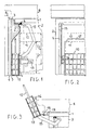
- the dishwasher machine comprises a machine body with walls which form a washing chamber, with a front loading opening.
- the upper wall (1) and a side wall (2) are partially visible.
- the loading opening is closed by a loading door (3), hinged at the bottom to the body of the machine and consisting of a front panel (4) and of a counterdoor panel, or simply a counterdoor (5).
- the counterdoor (5) made of stainless steel, is shaped by drawing to form a peripheral frame which, with the door closed, comes into contact with a sealing gasket 6, arranged near to the edges of the loading opening.
- control devices In the volume between the front panel and the upper side of the frame of the counterdoor (5), shown with a broken line and identified with the reference numeral (7), are housed the control devices, which can be accessed through the front panel or from the upper edge of the loading door, with the door slightly open.
- the machine can be built-in, as illustrated in figure 1, in which case a work surface (8) is placed on top of the upper wall (1) and a masking panel (9) is placed over the front panel (4).
- volume 7 can also be housed the measuring/dispensing device for detergent.
- control and detergent dispensing devices can be arranged in the upper wall (1), as described in the document EP0671143 ; or, in the case of the measurer, inside the washing chamber, as described in the document EP0602572 .
- auxiliary basket (10) arranged in the upper part of the recess and placed on top of the front face of the upper rack of the machine, schematically represented with the broken line (11) and having a vertical encumbrance (I1).
- a lower rack (42) is, however, arranged, usually with a greater length than that of the upper rack (11) and partially housed in the lower part of the counterdoor recess, or else consisting of a rack with an identical size as the one above to which an auxiliary basket similar to the auxiliary basket (10) is hooked.
- the upper rack (11), supported by removal guides (13), sliding between guiding rollers (14), can generally take up two different working positions, one represented by the broken line (11), the other by the broken line (12), which correspond to a vertical encumbrance (I2).
- the auxiliary basket (10) is supported by the upper rack (11), in a removable or permanent manner, the vertical position thereof is also variable itself, with the risk of interference of its load with the upper side of the frame of the counterdoor (5), when the loading door is closed.
- the drawback can be overcome in part by foreseeing different hooking positions of the auxiliary basket (10) to the upper rack (11) and entrusting the choice of the appropriate position to the diligence of the user, with the risk of the user committing an error.
- auxiliary basket (10) is advantageously supported by two arms, one of which (15) can be seen in figures 1,2,3, hinged at one end onto the side walls of the washing chamber, near to the roof of the chamber and rotating in the plane of the side walls.
- the auxiliary basket (10) is equipped with wings (16) for the hinged coupling with the opposite end of the arms (15).
- the arms (15) are arranged flush with the side walls of the washing chamber, at a convenient distance so as not to interfere with the gasket (6) on one side and with the sides of the upper rack (11) on the other.
- the auxiliary basket (10), supported by the arms (15), is arranged vertically in the counterdoor recess, at a height defined by the length of the arms and by the position of the hinging wings (16), with the rear face resting upon the front face of the upper rack (11).
- the lifting of the upper rack (11) causes a rotation of the arms which become arranged as illustrated in figure 3, in a stable position, ensured by balancing springs housed in the side walls of the machine and not illustrated or, more simply, by a stop device, consisting (fig. 3) of the latch eyelet (18) for closing shut the loading door, with which the machine is already usually provided and of a hook (19) with which the auxiliary basket (10) is supplied.
- the handle (17) can be of a size to carry out the confining template function for the load of the auxiliary basket (10), which must not extend outside of-the basket beyond the height of the handle (17), to avoid interference with the frame of the counterdoor (5), when the auxiliary basket (10) is replaced in the rest position and the door is closed.
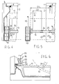
- auxiliary basket (10) is equipped with two short side arms (20), as seen in figure 6, with an end pin (21) which fits onto a saddle (22), formed in the stop head (23) with which the support guides (13) of the upper rack (11) are equipped.
- auxiliary basket (10) can be removed, only being hooked onto the heads (23), is indispensable for the following reason: as illustrated in fig. 5, in dishwasher machines the support guides (13) of the upper rack (11) can be removed from the washing chamber with a stroke C1 which does not allow the complete removal of the upper rack (11).
- the upper rack (11) is not integral with the support guides (13) but in turn is bound to the guides (13) by means of the rollers (24,25) or (26,27), when the upper rack (11) is mounted in the upper position) the axis of which is integral with the upper rack (11) and which can slide inside the support guides (13) and allow a relative stroke C2, between the support guides (13) and upper rack (11), which adds up to the stroke C1 of the support guides (13) and allows the complete removal of the upper rack (11).
- auxiliary basket (10) can take place with the auxiliary basket (10) installed or also and more conveniently with the auxiliary basket (10) removed and rested on a work surface.
- the handle (17) of the auxiliary basket (10) can carry out the function of a confining template.
- the rotor (28) which ensures the spraying of the crockery during the course of the wash cycle and which is mounted at the bottom to the upper rack (11) can have a diameter which partly occupies the counterdoor recess.
- the auxiliary basket (10) can conveniently be provided with an undercut (50) in its middle part, conveniently extending at a height in relation to the different heights that the rotor (28) can take up.
- Figure 7 shows a variant of the previous embodiment which does not require the removal of the auxiliary basket (10) from its support for the complete removal of the upper rack (11) from the washing chamber.
- the support guides (29, 38) of the upper rack (11) are of the telescopic type and are each equipped with an extension arm (30, 51), respectively, which increases the useful volume.
- a support is mounted, respectively (31,32) which can consist of a simple hinge eyelet, upon which the auxiliary basket (10) is hinged, for this purpose equipped with two pins (33,34), but preferably, as shown, it consists of a vertical plate with a slit and supporting saddles (35,36,37) at different heights, so as to be able to regulate the height of the auxiliary basket (10) as desired or simply to take the auxiliary basket (10) to an even more convenient height for the loading and unloading operations.
- the plates (31,32) and possibly a connection bar (39) between the two plates (31,32), extending between the tops of them constitute a fixed confining template (39) for controlling the vertical encumbrance of the objects arranged in the auxiliary basket (10) in relation to the available space in the counterdoor recess.
- the confining template (39) can be useful to hook the upper rack (11) in an upturned position, being conveniently equipped for this purpose with one or, as illustrated, two hooks (40,41).
- the auxiliary basket (10) To allow the free accessibility to the lower rack (42) of the machine and its removal it is sufficient, without removing the upper rack, to lift the auxiliary basket (10) into the slit of the plates (31,32) and possibly flip it onto the upper rack or hook it to the bar (39) in an upturned position.
- the auxiliary basket (10) is divided into two half-baskets (10A, 10B), which are not necessarily the same, respectively hinged, with a vertical axis of rotation, on the stop heads (43) of conventional support guides (44) of the upper rack (11).
- the two half-baskets (10A,10B) can be conveniently provided with a tile (45, 46), also only having a limited extension, which functions as a confining template for the vertical encumbrance of the load, as well as for a possible undercut (47) to avoid the interference with a rotor (28) with an increased diameter.
Landscapes
- Washing And Drying Of Tableware (AREA)
Claims (6)
- Lave-vaisselle domestique comportant un corps (1, 2) formant une chambre de lavage fermée par une porte frontale (3) articulée à la base du corps et pourvue d'un intervalle en contre-porte, comprenant un panier additionnel (10) logé dans ledit intervalle en complément d'un égouttoir supérieur (11) et d'un égouttoir supérieur (42) logés dans la chambre de lavage, caractérisé en ce que le panier additionnel (10) est associé au corps (1, 2) au moyen d'éléments intermédiaires (15, 22, 31, 32) autres que les égouttoirs supérieurs ou inférieurs (11, 42), ledit panier additionnel (10) ou lesdits éléments intermédiaires (15, 22, 31, 32) étant munis d'un gabarit (17, 39, 45, 46) pour délimiter l'encombrement vertical en charge du panier additionnel (10).
- Lave-vaisselle selon la revendication 1, dans lequel les éléments intermédiaires comportent deux bras rotatifs (15) avec une extrémité articulée au corps du lave-vaisselle par un axe horizontal, et l'autre extrémité articulée au panier additionnel (10).
- Lave-vaisselle selon la revendication 1, dans lequel les éléments intermédiaires comportent les têtes d'arrêt (23) de deux guides coulissants (13) retenant l'égouttoir supérieur (11), lesdites têtes étant munies d'un siège d'accrochage amovible (22) pour le panier additionnel (10).
- Lave-vaisselle selon la revendication 1, dans lequel les éléments intermédiaires comportent les têtes (31, 32) de bras d'extension télescopiques (30, 51) des guides (29) retenant l'égouttoir supérieur (11), lesdites têtes étant munies d'attaches articulées d'axe horizontal pour le panier additionnel (10).
- Lave-vaisselle selon la revendication 1, dans lequel le panier additionnel (10) est divisé en deux demi paniers indépendants (10A, 10B) et dans lequel les éléments intermédiaires comportent les têtes d'arrêts (43) de deux guides coulissants (43) retenant l'égouttoir supérieur (11), lesdites têtes étant munies d'attaches articulées d'axe vertical pour chacun desdits demi -panier additionnels, (10A, 10B).
- Lave-vaisselle selon la revendication 1, 2 ou 3, dans lequel le gabarit délimiteur est une poignée (17) permettant de déplacer le panier additionnel (10).
Priority Applications (2)
| Application Number | Priority Date | Filing Date | Title |
|---|---|---|---|
| EP20010830513 EP1281347B1 (fr) | 2001-08-01 | 2001-08-01 | Lave-vaisselle domestique avec un panier à couverts additionnel |
| DE2001630882 DE60130882T2 (de) | 2001-08-01 | 2001-08-01 | Geschirrspülmaschine mit einem zusätzlichen Besteckkorb |
Applications Claiming Priority (1)
| Application Number | Priority Date | Filing Date | Title |
|---|---|---|---|
| EP20010830513 EP1281347B1 (fr) | 2001-08-01 | 2001-08-01 | Lave-vaisselle domestique avec un panier à couverts additionnel |
Publications (2)
| Publication Number | Publication Date |
|---|---|
| EP1281347A1 EP1281347A1 (fr) | 2003-02-05 |
| EP1281347B1 true EP1281347B1 (fr) | 2007-10-10 |
Family
ID=8184641
Family Applications (1)
| Application Number | Title | Priority Date | Filing Date |
|---|---|---|---|
| EP20010830513 Expired - Lifetime EP1281347B1 (fr) | 2001-08-01 | 2001-08-01 | Lave-vaisselle domestique avec un panier à couverts additionnel |
Country Status (2)
| Country | Link |
|---|---|
| EP (1) | EP1281347B1 (fr) |
| DE (1) | DE60130882T2 (fr) |
Families Citing this family (13)
| Publication number | Priority date | Publication date | Assignee | Title |
|---|---|---|---|---|
| KR20040076668A (ko) * | 2003-02-26 | 2004-09-03 | 삼성전자주식회사 | 식기 세척기 |
| WO2005018407A2 (fr) * | 2003-08-26 | 2005-03-03 | Alpert Martin A | Lave-vaisselle et procede correspondant |
| DE102004035716A1 (de) * | 2004-07-23 | 2006-03-16 | BSH Bosch und Siemens Hausgeräte GmbH | Vorrichtung zur Besteckablage in Geschirrspülmaschinen |
| US9247859B2 (en) * | 2007-10-09 | 2016-02-02 | Duke Manufacturing Co. | Rack systems for use with kitchenware washing assemblies and related methods |
| TR200807468A1 (tr) | 2008-10-06 | 2010-04-21 | Bsh Ev Aletleri̇ San. Ve Ti̇c. A.Ş. | Bi̇r çatal-biçak sepeti̇ne sahi̇p bulaşik maki̇nesi̇ |
| DE102009028035A1 (de) * | 2009-07-27 | 2011-02-03 | BSH Bosch und Siemens Hausgeräte GmbH | Haushaltsgeschirrspülmaschine |
| US9931017B2 (en) | 2010-11-16 | 2018-04-03 | Martin A. Alpert | Washing apparatus and method with spiral air flow for drying |
| US9226643B2 (en) | 2012-04-10 | 2016-01-05 | General Electric Company | Silverware basket for a dishwasher appliance |
| EP2858546B1 (fr) * | 2012-06-06 | 2016-08-03 | Arçelik Anonim Sirketi | Panier qui convient pour être utilisé dans des lave-vaisselle, et lave-vaisselle dans lequel le panier est utilisé |
| US9848754B2 (en) | 2012-11-19 | 2017-12-26 | Whirlpool Corporation | Dish rack with dispenser unit |
| US9907452B2 (en) | 2014-10-02 | 2018-03-06 | Whirlpool Corporation | Dishwasher utensil caddies |
| KR102486273B1 (ko) * | 2017-08-31 | 2023-01-10 | 삼성전자주식회사 | 식기세척기 |
| PL3823509T3 (pl) * | 2018-07-19 | 2022-10-31 | Arçelik Anonim Sirketi | Zmywarka zawierająca mechanizm składanej półki |
Family Cites Families (5)
| Publication number | Priority date | Publication date | Assignee | Title |
|---|---|---|---|---|
| IT1159635B (it) * | 1983-11-18 | 1987-03-04 | Indesit | Cestello per macchine lavastoviglie |
| US4834125A (en) * | 1987-03-23 | 1989-05-30 | Whirlpool Corporation | Removable utensil basket for a dishwasher |
| US5069360A (en) * | 1990-08-27 | 1991-12-03 | Whirlpool Corporation | Silverware basket with cutaway divider |
| ITPN940014A1 (it) * | 1994-03-10 | 1995-09-10 | Zanussi Elettrodomestici | Lavastoviglie domestica |
| EP0963733A1 (fr) * | 1998-05-06 | 1999-12-15 | CANDY S.p.A. | Lave-vaiselle avec porte comportant un panier à couvert |
-
2001
- 2001-08-01 DE DE2001630882 patent/DE60130882T2/de not_active Expired - Lifetime
- 2001-08-01 EP EP20010830513 patent/EP1281347B1/fr not_active Expired - Lifetime
Also Published As
| Publication number | Publication date |
|---|---|
| DE60130882T2 (de) | 2008-07-17 |
| EP1281347A1 (fr) | 2003-02-05 |
| DE60130882D1 (de) | 2007-11-22 |
Similar Documents
| Publication | Publication Date | Title |
|---|---|---|
| EP1281347A1 (fr) | Lave-vaisselle domestique avec un panier à couverts additionnel | |
| US8104628B2 (en) | Dishwasher rack having slidably coupled tine holder and tine rack | |
| KR102512217B1 (ko) | 식기세척기 | |
| EP2326237B1 (fr) | Lave-vaisselle avec tiroir fixé à un toit de cuve | |
| KR102393509B1 (ko) | 수납부 및 이를 이용한 식기 세척기 | |
| US8028548B2 (en) | Laundry machine with height increasing member and drainage filter servicing section | |
| CN106551670A (zh) | 洗碗机 | |
| US7694844B2 (en) | Spoon basket structure of dish washer | |
| US11471023B2 (en) | Front and top loading dishwasher with restricted basket movement | |
| EP3332686B1 (fr) | Ensemble panier de lavage et ensemble plateau utilisés pour machine à laver à cuve, et machine à laver à cuve | |
| EP0575300B1 (fr) | Dispositif pour une porte de machine à laver la vaisselle | |
| KR101159039B1 (ko) | 식기 세척기 | |
| EP1413241A1 (fr) | Machine à laver vaiselle avec un panier superieur positionné partiellment dans une cavité de la porte et equipé avec une tablette frontale basculable | |
| KR100600764B1 (ko) | 하측 개방형 도어를 갖는 드럼 세탁기 | |
| EP4397228A1 (fr) | Lave-vaisselle | |
| JP2016168204A (ja) | 食器洗浄乾燥機 | |
| EP3151715B1 (fr) | Lave-vaisselle comportant un moyen d'élévation | |
| KR101210124B1 (ko) | 식기 세척기의 랙구조 | |
| KR102413327B1 (ko) | 높이 조절이 가능한 수납부 및 이를 이용한 식기 세척기 | |
| CN108056718B (zh) | 水槽式清洗机的开盖结构 | |
| EP4461195A1 (fr) | Lave-vaisselle | |
| US2290116A (en) | Dishwashing machine | |
| US20060037631A1 (en) | Warewash machine and related door construction | |
| CN220344372U (zh) | 用于洗碗机的置物架、碗篮组件及洗碗机 | |
| EP0432281B1 (fr) | Dispositif de chargement pour lave-vaisselle |
Legal Events
| Date | Code | Title | Description |
|---|---|---|---|
| PUAI | Public reference made under article 153(3) epc to a published international application that has entered the european phase |
Free format text: ORIGINAL CODE: 0009012 |
|
| 17P | Request for examination filed |
Effective date: 20020305 |
|
| AK | Designated contracting states |
Designated state(s): AT BE CH CY DE DK ES FI FR GB GR IE IT LI LU MC NL PT SE TR |
|
| AX | Request for extension of the european patent |
Extension state: AL LT LV MK RO SI |
|
| AKX | Designation fees paid |
Designated state(s): DE FR GB IT |
|
| GRAP | Despatch of communication of intention to grant a patent |
Free format text: ORIGINAL CODE: EPIDOSNIGR1 |
|
| GRAS | Grant fee paid |
Free format text: ORIGINAL CODE: EPIDOSNIGR3 |
|
| GRAA | (expected) grant |
Free format text: ORIGINAL CODE: 0009210 |
|
| AK | Designated contracting states |
Kind code of ref document: B1 Designated state(s): DE FR GB IT |
|
| REG | Reference to a national code |
Ref country code: GB Ref legal event code: FG4D |
|
| REF | Corresponds to: |
Ref document number: 60130882 Country of ref document: DE Date of ref document: 20071122 Kind code of ref document: P |
|
| ET | Fr: translation filed | ||
| PLBE | No opposition filed within time limit |
Free format text: ORIGINAL CODE: 0009261 |
|
| STAA | Information on the status of an ep patent application or granted ep patent |
Free format text: STATUS: NO OPPOSITION FILED WITHIN TIME LIMIT |
|
| 26N | No opposition filed |
Effective date: 20080711 |
|
| PGFP | Annual fee paid to national office [announced via postgrant information from national office to epo] |
Ref country code: GB Payment date: 20130821 Year of fee payment: 13 Ref country code: FR Payment date: 20130902 Year of fee payment: 13 |
|
| PGFP | Annual fee paid to national office [announced via postgrant information from national office to epo] |
Ref country code: IT Payment date: 20130809 Year of fee payment: 13 |
|
| PGFP | Annual fee paid to national office [announced via postgrant information from national office to epo] |
Ref country code: DE Payment date: 20131031 Year of fee payment: 13 |
|
| REG | Reference to a national code |
Ref country code: DE Ref legal event code: R119 Ref document number: 60130882 Country of ref document: DE |
|
| GBPC | Gb: european patent ceased through non-payment of renewal fee |
Effective date: 20140801 |
|
| PG25 | Lapsed in a contracting state [announced via postgrant information from national office to epo] |
Ref country code: IT Free format text: LAPSE BECAUSE OF NON-PAYMENT OF DUE FEES Effective date: 20140801 |
|
| REG | Reference to a national code |
Ref country code: DE Ref legal event code: R119 Ref document number: 60130882 Country of ref document: DE Effective date: 20150303 |
|
| REG | Reference to a national code |
Ref country code: FR Ref legal event code: ST Effective date: 20150430 |
|
| PG25 | Lapsed in a contracting state [announced via postgrant information from national office to epo] |
Ref country code: DE Free format text: LAPSE BECAUSE OF NON-PAYMENT OF DUE FEES Effective date: 20150303 Ref country code: GB Free format text: LAPSE BECAUSE OF NON-PAYMENT OF DUE FEES Effective date: 20140801 |
|
| PG25 | Lapsed in a contracting state [announced via postgrant information from national office to epo] |
Ref country code: FR Free format text: LAPSE BECAUSE OF NON-PAYMENT OF DUE FEES Effective date: 20140901 |