EP1281462A2 - Machine-outil et procédé pour l'usinage de pièces - Google Patents
Machine-outil et procédé pour l'usinage de pièces Download PDFInfo
- Publication number
- EP1281462A2 EP1281462A2 EP02011228A EP02011228A EP1281462A2 EP 1281462 A2 EP1281462 A2 EP 1281462A2 EP 02011228 A EP02011228 A EP 02011228A EP 02011228 A EP02011228 A EP 02011228A EP 1281462 A2 EP1281462 A2 EP 1281462A2
- Authority
- EP
- European Patent Office
- Prior art keywords
- actuating
- workpiece holder
- spindle
- head
- workpiece
- Prior art date
- Legal status (The legal status is an assumption and is not a legal conclusion. Google has not performed a legal analysis and makes no representation as to the accuracy of the status listed.)
- Withdrawn
Links
Images


Classifications
-
- B—PERFORMING OPERATIONS; TRANSPORTING
- B23—MACHINE TOOLS; METAL-WORKING NOT OTHERWISE PROVIDED FOR
- B23Q—DETAILS, COMPONENTS, OR ACCESSORIES FOR MACHINE TOOLS, e.g. ARRANGEMENTS FOR COPYING OR CONTROLLING; MACHINE TOOLS IN GENERAL CHARACTERISED BY THE CONSTRUCTION OF PARTICULAR DETAILS OR COMPONENTS; COMBINATIONS OR ASSOCIATIONS OF METAL-WORKING MACHINES, NOT DIRECTED TO A PARTICULAR RESULT
- B23Q3/00—Devices holding, supporting, or positioning work or tools, of a kind normally removable from the machine
- B23Q3/16—Devices holding, supporting, or positioning work or tools, of a kind normally removable from the machine controlled in conjunction with the operation of the tool
-
- B—PERFORMING OPERATIONS; TRANSPORTING
- B23—MACHINE TOOLS; METAL-WORKING NOT OTHERWISE PROVIDED FOR
- B23Q—DETAILS, COMPONENTS, OR ACCESSORIES FOR MACHINE TOOLS, e.g. ARRANGEMENTS FOR COPYING OR CONTROLLING; MACHINE TOOLS IN GENERAL CHARACTERISED BY THE CONSTRUCTION OF PARTICULAR DETAILS OR COMPONENTS; COMBINATIONS OR ASSOCIATIONS OF METAL-WORKING MACHINES, NOT DIRECTED TO A PARTICULAR RESULT
- B23Q2230/00—Special operations in a machine tool
- B23Q2230/002—Using the spindle for performing a non machining or non measuring operation, e.g. cleaning, actuating a mechanism
Definitions
- the invention relates to a machine tool with a workpiece holder, in particular by operating an actuator bar or disc-shaped workpieces can be clamped and a spindle head with a tool spindle accommodated in it, into the tools for machining the workpieces can be clamped, the spindle head and the workpiece holder are movable relative to each other.
- the invention further relates to a method for processing in particular rod-shaped or disc-shaped workpieces Using a machine tool, a workpiece holder, in the workpieces can be clamped by actuating an adjusting element are, as well as a spindle head with a Tool spindle has in the tools for machining the workpieces can be clamped.
- the invention relates to a workpiece holder as well a new adjustment head for this.
- a machine tool, a method and a workpiece holder this type are known from DE 196 35 258 C1.
- the known machine tool is a traveling column machine for the drilling, turning and milling of preferably rods or disc-shaped workpieces.
- the Machine tool On a machine bed the Machine tool is a workpiece holder in the form of a Chuck arranged, which are provided with a rotary drive to enable the workpieces to be turned.
- the Rotatability of the chuck also allows the workpiece when drilling or milling around its longitudinal axis adjust so that machining on all four Long sides of the workpiece with the help of in the tool spindle clamped tools is possible.
- the chuck is about a perpendicular to its longitudinal axis Cross axis pivotally mounted. Will the chuck e.g. swiveled upwards by 90 °, so can the end face of the workpiece by means of one inserted into the tool spindle Tool can be edited.
- this task solved in that the machine tool one of the tool spindle drivable actuator for actuating the Has actuator.
- the invention is based on the knowledge that through the anyway an existing drive spindle is already available with which the workpiece holder can be operated very precisely leaves.
- Tool spindles have a complex one Drive and control technology, so that exactly have defined torques generated.
- the angle of rotation of the tool spindle can also be precisely controlled.
- the actuating element which can be driven by the tool spindle the precisely controllable rotary movement of the Transfer the tool spindle to a control element in a controlled manner, that on the workpiece holder for actuating a clamping device is provided.
- the workpiece holder therefore does not require any drives for actuation the tensioning device, which makes its construction significant simplified and increased reliability. Nevertheless it can may be useful in individual cases for various reasons, nevertheless Provide drives in the workpiece holder. So can e.g. simple drives can be useful if occasionally Workpieces are to be clamped very quickly in which it does not depend on precisely maintained clamping forces.
- the actuation of the control element on the workpiece holder requires it that the actuator is first in one position is transferred in which it can act on the actuator. Since the actuating element is preferably directly in the tool spindle used or held on the spindle head is that it can be driven by the tool spindle, this can through a relative process between which the tool spindle receiving spindle head and the workpiece holder, it is irrelevant whether the spindle head is opposite the fixed workpiece holder, this compared to the fixed Move the spindle head or even both parts at the same time become. Depending on the spatial position of the direction of actuation, in which the control element can be actuated (e.g.
- the actuation of the control element for clamping the workpiece in the workpiece holder can be done once before machining the Workpiece.
- the actuator is then first to connect to the tool spindle and after clamping exchange for a tool. After finishing the editing by one or more tools the actuator reconnected to the tool spindle and the actuator actuated accordingly for clamping the workpiece.
- the workpiece in the To clamp the workpiece holder e.g. also the one previously clamped Area of the workpiece, i.e. the so-called 6th side, to be able to machine after turning the workpiece by 180 °.
- the actuating element is also in the meantime to connect with the tool spindle, so usually in this clamp.
- connection of the actuator with the tool spindle can be done manually, but also automatically.
- the actuating element can e.g. in a tool magazine be stored from where it is from the spindle head approached or fed by a handling device can be.
- the invention applies to all types of workpiece holders applicable; however, there are special advantages if the workpiece holder as a chuck with several jaws is formed, which in a radial direction Purposes of clamping and unclamping by pressing the Adjusting element are adjustable.
- the entire movement can be done with just one adjustment Activate workpiece holder. This will increase the number of Traversing movements between the workpiece holder and the tool spindle kept small.
- actuating element is rotated can be actuated and the actuating element is a screwdriver.
- the actuating element is of a very simple design possible, because this then e.g. as a simple chuck key or screwdriver with a trained on it usual tool holder, e.g. with hollow shank taper (HSK), can be carried out, just like that for editing the Workpieces provided tools clamped in the tool spindle becomes.
- actuating elements that can be activated by turning them frequently used in conventional chucks, e.g. in shape a pinion or a threaded spindle.
- the actuating element part of a detachable on the spindle head and non-rotatably adjustable adjustment head.
- the adjustment head is also advantageous for workpiece holders, which operate by turning the control element to let.
- the non-rotatable attachment of the adjustment head to the The spindle head allows the transmission of counter moments between the adjustment head and the spindle head, so that in the Adjustment head gear can be arranged.
- the adjustment head can be used to secure it to the spindle head e.g. form-fitting with pin or similar in accordingly shaped recesses formed on the spindle head become.
- the actuating element of the adjustment head is then simultaneously via a coupling part, e.g. a hollow shaft cone ,, connected to the tool spindle.
- the adjustment head can be like a normal tool in a tool magazine stored and automatically attached to the spindle head, usually be clamped in its tool holder.
- the adjustment head has another Actuating element that has a different actuation direction than that has an actuator.
- a second actuating element with a different actuating direction allows to work in both horizontal as well as in the vertical position of the chuck.
- Disc-shaped workpieces are preferred in vertical Position of the chuck clamped, as this is due to the Gravity usually due to its own weight in vertical Lay securely on the support points and then excited can be.
- Wave-shaped or rod-shaped workpieces are often used with the support of a Bezel or a counter tip in the horizontal position of the chuck inserted and excited.
- Another advantage is the fact that the number of travel operations between the spindle head and the workpiece holder is reduced. This aspect comes into play when the Spindle head and the workpiece holder can be pivoted relative to one another are, e.g. for the purpose of 5-page editing of the Workpieces, it does not matter whether the workpiece holder or the spindle head is pivoted.
- the actuator is now in two different relative pivot positions between the Workpiece holder and the spindle head by one actuator each reachable.
- the second actuator can thus be the average Travel path that is required to be significantly reduced from a first position in which the workpiece with a tool can be processed to reach a second position in which the workpiece using one of the actuators can be spanned.
- the invention therefore also relates to a device of this type Adjustment head with two actuators, which in different Directions work.
- this embodiment acts the one actuator parallel to an axis of rotation of the Tool spindle and the other actuator vertically For this.
- the workpiece holder another control element, by its actuation also a clamping or unclamping is effected and that in a different direction of actuation than the one control element can be actuated.
- such a second control element has the same Effect like the second actuator described above.
- the workpieces can also be clamp in the most favorable position and further reduce the travel, the transition from processing to input, Unclamping or reclamping of the workpiece or vice versa required are.
- a workpiece holder especially a chuck that like described above two actuators with different Has actuation directions is also the subject of Invention.
- a chuck is used as the workpiece holder as mentioned above is used, it is also preferred if the one Control element in the radial direction and the further control element in the axial direction with respect to a longitudinal axis of the chuck can be actuated.
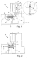
- FIG. 1 shows a machine tool according to the invention in one very simplified, not to scale representation shown and designated a total of 10.
- the machine tool points a traveling column 12, which is indicated in an arrow 14 X direction and in a direction perpendicular to the paper plane running Y direction movable on a machine frame 16 is arranged.
- a spindle head 18 is located on the traveling column 12 Can be moved in a Z direction indicated by an arrow 20 attached. Together with the traveling column 12 is the spindle head thus movable in all three spatial directions.
- the spindle head 18 takes a tool spindle indicated by dashed lines 22 and drive and control devices not shown in FIG. 1 with which the tool spindle 22 with high accuracy in a rotary movement around a designated 24 Can move axis of rotation.
- the machine tool 10 also has a workpiece holder 26 on, shown in simplified form in Fig. 1 in an axial section is.
- the workpiece holder 26 is a 3-jaw chuck trained and thereby in particular to accommodate rod-shaped or disc-shaped workpieces.
- jaws 28 of the workpiece holder 26 are by an actuator 30 in a radial direction for the purpose of input and Unclamping a workpiece 32 adjustable.
- the actuator 30 acts on a tensioning device, not shown in FIG. 1, the force exerted on the control element evenly transfers to the jaws 28.
- the workpiece holder 26 is about its longitudinal axis designated 34 rotatably supported in a manner not shown and provided with its own drive so that the machine tool 10 enables the workpiece 32 to be turned. Moreover is the entire workpiece holder 26 on a bridge 36 by one in the Y direction transverse axis pivotally mounted, such as this is indicated in Fig. 1 by an arrow 38.
- An actuating element is in the tool spindle 20 like a conventional tool clamped in the form of a screwdriver 40 which, as can be seen from the enlarged view, a hollow shaft cone 42 for clamping in the tool spindle 20 and one Has wrench 44. With the wrench 44 the actuating element 30 of the workpiece holder 26 can be actuated.
- FIG. 1 shows the machine tool 10 in one state machining of the workpiece 32 with one in the tool spindle 20 tools used, e.g. a turning tool. If the workpiece is now to be unclamped or reclamped, as shown in Fig. 1, the screwdriver 40 in the tool spindle 20 clamped. Then the spindle head 18 move in such a way that the screwdriver 40 comes into a position, in which he attack the actuator 30 and this can operate. This state is shown in Fig. 2.
- the jaws 28 are released, as shown by arrows 46 is indicated.
- the workpiece 32 can now be done manually or mechanically moved in the workpiece holder (see arrow 48), from this removed and reintroduced in a changed position or be replaced by another workpiece.
- the tool spindle 22 is set in rotation, to tighten the control element 30 via the screwdriver 40.
- torques applied by the tool spindle can be, the workpiece can be precisely with the Clamp the specified clamping forces in the workpiece holder.
- FIG. 3 and 4 show another embodiment of the invention, in which an adjustment head 50 on the spindle head 18 is attached that it is driven by the tool spindle 22 becomes.
- the adjustment head 50 bolts 52 on, with which he in corresponding recesses is inserted on the end face of the spindle head 18.
- the adjustment head 50 is non-rotatably on the spindle head 18 held.
- the adjustment head 50 is attached here also via a hollow shaft cone formed thereon 54, which is clamped in the tool spindle 22.
- about an indicated gear 56 is the hollow shaft taper 54 with two actuating elements 58 arranged perpendicular to one another and 60 connected when the tool spindle rotates 22 rotate synchronously, as indicated by arrows 62 and 64 is.
- the swivel-mounted workpiece holder 26 is located when clamping, unclamping or reclamping as shown in Fig. 2 in a horizontal but in a vertical position for Clamping, for example, disk-shaped workpieces, that indicates Adjustment element 30 no longer upwards or into another radial Position from where it is by simply turning the workpiece holder 26 about the longitudinal axis 34 in the position shown in FIG. 2 can be transferred. Rather, the control element 30 now only accessible from the side. When using the Screwdriver 40 from FIGS. 1 and 2 would therefore have to hold the workpiece 26 first pivoted back into a horizontal position to be operated by the screwdriver 40 to allow.
- FIG. 5 and 6 show a further embodiment of the Invention, in which not an adjustment head 50, but one Workpiece holder allows 66 different actuation directions.
- the workpiece holder 66 has in addition to the Actuating element 30, which is to be actuated radially, a second Actuator 70 which axially, i.e. from the front of the Workpiece holder 66 forth, can be actuated. If how 6, the workpiece holder 66 in a vertical Position, the second actuator 70 vertically above, so that it from a simple screwdriver 40, as related 1 and 2 has already been explained, actuated can be. An adjustment head is in this embodiment therefore not necessary because the workpiece holder 66 itself allows a second direction of actuation.
- Fig. 7 shows a simplified schematic diagram, which is in a radial Section of some essential parts of FIGS. 5 and 6 workpiece holder 66 shown.
- the longitudinal axis 34 of the Workpiece holder 66 runs through in this illustration Axis of symmetry of a toothed ring 72, which on the one hand over one of attacking the underside, i.e. acting in the plane of the drawing Pinion 74, on the other via a pinion 76, the transverse acts to the plane of the drawing, set in rotation about the longitudinal axis 34 can be.
- the pinion 74 is with a pivot pin 78 connected to hexagon head 80.
- the pivot pin 78 forms the first, in the radial direction, i.e.
- Fig. 8 shows the basic structure in an axial section of the adjusting head 50 shown in FIGS. 3 and 4.
- the transmission 56 has three arranged at right angles to each other Spur gears 83, 84 and 86 on which a rotation of the with the hollow shaft taper 54 in a manner not shown firmly connected main shaft 88 on the two actuators 58 and 60 with a gear ratio of 1: 1 transfer.
Landscapes
- Engineering & Computer Science (AREA)
- Mechanical Engineering (AREA)
- Machine Tool Units (AREA)
- Gripping On Spindles (AREA)
- Cutting Tools, Boring Holders, And Turrets (AREA)
- Automatic Tool Replacement In Machine Tools (AREA)
Applications Claiming Priority (2)
| Application Number | Priority Date | Filing Date | Title |
|---|---|---|---|
| DE2001138748 DE10138748B4 (de) | 2001-07-30 | 2001-07-30 | Werkzeugmaschine |
| DE10138748 | 2001-07-30 |
Publications (2)
| Publication Number | Publication Date |
|---|---|
| EP1281462A2 true EP1281462A2 (fr) | 2003-02-05 |
| EP1281462A3 EP1281462A3 (fr) | 2004-01-21 |
Family
ID=7694666
Family Applications (1)
| Application Number | Title | Priority Date | Filing Date |
|---|---|---|---|
| EP02011228A Withdrawn EP1281462A3 (fr) | 2001-07-30 | 2002-05-22 | Machine-outil et procédé pour l'usinage de pièces |
Country Status (2)
| Country | Link |
|---|---|
| EP (1) | EP1281462A3 (fr) |
| DE (1) | DE10138748B4 (fr) |
Cited By (2)
| Publication number | Priority date | Publication date | Assignee | Title |
|---|---|---|---|---|
| US7631407B2 (en) * | 2006-02-13 | 2009-12-15 | Stama Maschinenfabrik Gmbh | Machine tool and method for cutting machining of work pieces |
| US20220032476A1 (en) * | 2020-07-30 | 2022-02-03 | Saab Seaeye Limited | Tool attachment, tool changer and corresponding method of use |
Family Cites Families (5)
| Publication number | Priority date | Publication date | Assignee | Title |
|---|---|---|---|---|
| DE2940560A1 (de) * | 1979-10-06 | 1981-04-09 | Emag Maschinenfabrik Gmbh, 7335 Salach | Ladevorrichtung fuer cnc-gesteuerte frontdrehmaschinen |
| US4511295A (en) * | 1982-09-20 | 1985-04-16 | Vadim Razdobreev | Pneumatic collet release tool |
| US4571814A (en) * | 1984-12-14 | 1986-02-25 | Palfery Kenneth J | Automated machining system |
| DE3714070A1 (de) * | 1987-04-28 | 1988-11-10 | Schmidt & Co Gmbh Kranz | Hydraulische spannvorrichtung zum spannen eines spannfutters einer drehbank |
| DE19635258C1 (de) * | 1996-08-30 | 1998-02-12 | Stama Maschinenfabrik Gmbh | Bohr- und Fräswerk zum Verarbeiten von Werkstoffstangen |
-
2001
- 2001-07-30 DE DE2001138748 patent/DE10138748B4/de not_active Expired - Fee Related
-
2002
- 2002-05-22 EP EP02011228A patent/EP1281462A3/fr not_active Withdrawn
Cited By (3)
| Publication number | Priority date | Publication date | Assignee | Title |
|---|---|---|---|---|
| US7631407B2 (en) * | 2006-02-13 | 2009-12-15 | Stama Maschinenfabrik Gmbh | Machine tool and method for cutting machining of work pieces |
| US20220032476A1 (en) * | 2020-07-30 | 2022-02-03 | Saab Seaeye Limited | Tool attachment, tool changer and corresponding method of use |
| US12070849B2 (en) * | 2020-07-30 | 2024-08-27 | Saab Seaeye Limited | Tool attachment, tool changer and corresponding method of use |
Also Published As
| Publication number | Publication date |
|---|---|
| DE10138748A1 (de) | 2003-02-27 |
| EP1281462A3 (fr) | 2004-01-21 |
| DE10138748B4 (de) | 2006-04-20 |
Similar Documents
| Publication | Publication Date | Title |
|---|---|---|
| EP0547554B1 (fr) | Appareil de serrage pour usiner en muti-faces | |
| DE2711904A1 (de) | Spannfutter fuer drehmaschinen | |
| DE3509635C1 (de) | Werkzeughalteeinrichtung fuer Drehmaschinen | |
| EP1260307A2 (fr) | Machine-outil et procédé d'usinage d'une pièce en forme de barre | |
| DE2818018C2 (fr) | ||
| EP0761383A2 (fr) | Machine-outil | |
| EP1289711B1 (fr) | Dispositif de prehension et de transport de pieces dans des machines rotatives | |
| DE3528120C1 (de) | Kraftbetaetigtes Spannfutter | |
| EP0761384A1 (fr) | Machine-outil | |
| DE3038779C2 (de) | Gewindeschneidemaschine für Rohre | |
| EP0787560B1 (fr) | Dispositif d'usinage des barres, des profilés et similaire | |
| DE2631583C3 (de) | Kraftbetätigtes Spannfutter | |
| DE10138748B4 (de) | Werkzeugmaschine | |
| DE1289499B (de) | Geraet fuer das Einsetzen von Blindmuttern in einen Bauteil | |
| DE3844343C2 (de) | Kraftbetätigtes Backenspannfutter für exzentrisch zu spannende Werkstücke, insbesondere Kurbelwellen | |
| DE1552250B2 (de) | Formdrehautomat | |
| DE2648997A1 (de) | Spannwerkzeug mit einzelverstellung und zusaetzlicher zentralspannung | |
| DE69033337T2 (de) | Rohrendbearbeitungswerkzeug mit verbesserten Torsionreaktion und Spannmöglichkeiten | |
| DE19537070C2 (de) | Werkzeugmaschine mit einer Werkzeugwechseleinrichtung | |
| DE19537071C2 (de) | Mit einem Plandrehkopf bestückte Werkzeugmaschine | |
| DE102010015651A1 (de) | Verfahren zur Bearbeitung von Werkstücken | |
| DE10147649A1 (de) | Fräsaggregat | |
| DE10145673A1 (de) | Werkzeugmaschine zur Bearbeitung eines stangenförmigen Werkstücks | |
| DE933124C (de) | Kopier-Fraes- oder Schleifmaschine, insbesondere fuer Luftschraubenblaetter | |
| DE2544074C2 (de) | Vorrichtung an einem Mehrspindeldrehautomaten zum Einfräsen von Schlitzen in Werkstücke |
Legal Events
| Date | Code | Title | Description |
|---|---|---|---|
| PUAI | Public reference made under article 153(3) epc to a published international application that has entered the european phase |
Free format text: ORIGINAL CODE: 0009012 |
|
| AK | Designated contracting states |
Designated state(s): AT BE CH CY DE DK ES FI FR GB GR IE IT LI LU MC NL PT SE TR |
|
| AX | Request for extension of the european patent |
Extension state: AL LT LV MK RO SI |
|
| PUAL | Search report despatched |
Free format text: ORIGINAL CODE: 0009013 |
|
| AK | Designated contracting states |
Kind code of ref document: A3 Designated state(s): AT BE CH CY DE DK ES FI FR GB GR IE IT LI LU MC NL PT SE TR |
|
| AX | Request for extension of the european patent |
Extension state: AL LT LV MK RO SI |
|
| AKX | Designation fees paid | ||
| REG | Reference to a national code |
Ref country code: DE Ref legal event code: 8566 |
|
| STAA | Information on the status of an ep patent application or granted ep patent |
Free format text: STATUS: THE APPLICATION IS DEEMED TO BE WITHDRAWN |
|
| 18D | Application deemed to be withdrawn |
Effective date: 20040722 |