EP1281473A2 - Lathe with workpiece spindle and raidally supporting workpiece guide - Google Patents
Lathe with workpiece spindle and raidally supporting workpiece guide Download PDFInfo
- Publication number
- EP1281473A2 EP1281473A2 EP02016078A EP02016078A EP1281473A2 EP 1281473 A2 EP1281473 A2 EP 1281473A2 EP 02016078 A EP02016078 A EP 02016078A EP 02016078 A EP02016078 A EP 02016078A EP 1281473 A2 EP1281473 A2 EP 1281473A2
- Authority
- EP
- European Patent Office
- Prior art keywords
- lathe according
- workpiece
- guide
- force
- lathe
- Prior art date
- Legal status (The legal status is an assumption and is not a legal conclusion. Google has not performed a legal analysis and makes no representation as to the accuracy of the status listed.)
- Granted
Links
Images





Classifications
-
- B—PERFORMING OPERATIONS; TRANSPORTING
- B23—MACHINE TOOLS; METAL-WORKING NOT OTHERWISE PROVIDED FOR
- B23B—TURNING; BORING
- B23B7/00—Automatic or semi-automatic turning-machines with a single working-spindle, e.g. controlled by cams; Equipment therefor; Features common to automatic and semi-automatic turning-machines with one or more working-spindles
- B23B7/02—Automatic or semi-automatic machines for turning of stock
- B23B7/06—Automatic or semi-automatic machines for turning of stock with sliding headstock
-
- B—PERFORMING OPERATIONS; TRANSPORTING
- B23—MACHINE TOOLS; METAL-WORKING NOT OTHERWISE PROVIDED FOR
- B23Q—DETAILS, COMPONENTS, OR ACCESSORIES FOR MACHINE TOOLS, e.g. ARRANGEMENTS FOR COPYING OR CONTROLLING; MACHINE TOOLS IN GENERAL CHARACTERISED BY THE CONSTRUCTION OF PARTICULAR DETAILS OR COMPONENTS; COMBINATIONS OR ASSOCIATIONS OF METAL-WORKING MACHINES, NOT DIRECTED TO A PARTICULAR RESULT
- B23Q1/00—Members which are comprised in the general build-up of a form of machine, particularly relatively large fixed members
- B23Q1/72—Auxiliary arrangements; Interconnections between auxiliary tables and movable machine elements
- B23Q1/76—Steadies; Rests
-
- B—PERFORMING OPERATIONS; TRANSPORTING
- B23—MACHINE TOOLS; METAL-WORKING NOT OTHERWISE PROVIDED FOR
- B23Q—DETAILS, COMPONENTS, OR ACCESSORIES FOR MACHINE TOOLS, e.g. ARRANGEMENTS FOR COPYING OR CONTROLLING; MACHINE TOOLS IN GENERAL CHARACTERISED BY THE CONSTRUCTION OF PARTICULAR DETAILS OR COMPONENTS; COMBINATIONS OR ASSOCIATIONS OF METAL-WORKING MACHINES, NOT DIRECTED TO A PARTICULAR RESULT
- B23Q15/00—Automatic control or regulation of feed movement, cutting velocity or position of tool or work
- B23Q15/007—Automatic control or regulation of feed movement, cutting velocity or position of tool or work while the tool acts upon the workpiece
- B23Q15/013—Control or regulation of feed movement
-
- G—PHYSICS
- G05—CONTROLLING; REGULATING
- G05B—CONTROL OR REGULATING SYSTEMS IN GENERAL; FUNCTIONAL ELEMENTS OF SUCH SYSTEMS; MONITORING OR TESTING ARRANGEMENTS FOR SUCH SYSTEMS OR ELEMENTS
- G05B2219/00—Program-control systems
- G05B2219/30—Nc systems
- G05B2219/41—Servomotor, servo controller till figures
- G05B2219/41109—Drilling rate, feed rate
-
- G—PHYSICS
- G05—CONTROLLING; REGULATING
- G05B—CONTROL OR REGULATING SYSTEMS IN GENERAL; FUNCTIONAL ELEMENTS OF SUCH SYSTEMS; MONITORING OR TESTING ARRANGEMENTS FOR SUCH SYSTEMS OR ELEMENTS
- G05B2219/00—Program-control systems
- G05B2219/30—Nc systems
- G05B2219/42—Servomotor, servo controller kind till VSS
- G05B2219/42168—Measuring of needed force for servo
Definitions
- the invention relates to a lathe comprising a machine frame, a Workpiece spindle arranged on the machine frame and rotatable about a spindle axis with a holder for a workpiece, at least one tool holder with at least one tool for machining the workpiece, a guide device for radial support of the workpiece of a guide element, which for this purpose with an actuator adjustable radial force acts on an outer surface of the workpiece, the Guide device and the workpiece when machining the same relative are movable relative to each other in the direction of the spindle axis.
- the invention is therefore based on the object of a lathe Generic type to improve such that the guide device with measures that are as simple as possible can be optimally adjusted.
- This task is carried out in a lathe of the type described above solved according to the invention in that the lathe with a detection device for a feed force that is required to the workpiece and the guide element relative to one another in the direction of the spindle axis move, is provided.
- the feed force provides a measure of the quality of the Management facility adjustment.
- the detection device for the pushing force can be in the most varied of ways Way to be effective.
- the detection device detects the Relative movement between the workpiece and the guide element effecting feed drive is assigned.
- the detection device detects that of the Feed drive generated feed force detected.
- This pushing force is not necessarily directly proportional to the pushing force, which is required to move the workpiece in the direction of the spindle axis to move relative to the guide element.
- This feed force leaves however, in a simple manner, for example by means of correction variables modify that the modified feed force is approximately proportional relative to the desired feed force for moving the workpiece to the guide element.
- the detected pushing force is corrected by this subtracts the forces that are required to all with the Feed drive coupled devices, such as the spindle or the tailstock to move without friction between the workpiece and the guide element prevails, so that the modified one determined thereby Feeding force essentially that of the friction between the workpiece and guide element conditional pushing force corresponds.
- the pushing force can then be recorded in a particularly simple manner, if the detection device generates the one generated by the feed drive Feed force recorded.
- the actually measured pushing force a force representing the friction in the feed guide subtract.
- the feed force is particularly simple in the case of a feed drive then detect when the detection device, the torque of the feed drive detected.
- Torque detection of this type is conventional, for example Torque sensors can be implemented.
- the feed drive is an electric feed drive and the detection device is the current consumption of the electrical Feed drive includes, since the current consumption is directly proportional to the force generated by the feed drive.
- the Guide device In order for an operator of the lathe to adjust the Guide device, in particular the radial force of the guide element facilitate, it is particularly favorable if a display device for Providing the pushing force is provided because with such a display device information of the user in a simple manner about the determined pushing force is possible.
- the display can be done in many different ways. For example an acoustic display by the display device would be conceivable.
- Such a visual display could, for example, take the form of numerical values. However, it is even better if the display device has the feed force in Displays the shape of a graphic chart.
- the display device in addition to the pushing force at least one Indicates reference value, it being particularly useful if the The reference value and the pushing force are displayed simultaneously, so that quality by directly comparing both values of the operator conveyed the setting of the guide device in a particularly simple manner can be.
- the display device the reference value and the pushing force on the same scale displays.
- the display device visually, in particular the at least one reference value in the form of a graphic diagram.
- the Display device the at least one reference value in the form of a value range displays.
- the display device contains the reference values by a desired range of values and undesired ranges of values displays, so that for an operator a quickly understandable comparison can be made.
- the display device the at least one Reference value depending on a processing parameter set, comprising determined at least one parameter.
- the processing parameter set and the associated at least one Reference value in a memory assigned to the display device are saved. This allows, if the machining parameters are available in simply call up the reference value.
- the reference value can be determined particularly favorably if the Display device an input device for entering the parameters of the Processing parameter set is assigned so that the operator only has the task of at least one in the respective processing To record and enter parameters of the machining parameter set in order to then the reference value for an optimal feed force is immediately available to have.
- the adjusting device for adjusting the Radial force is adjustable by an actuator.
- Such an actuator could be designed so that it is a kind "Remote controlled setting" of the control device allows.
- a particularly inexpensive solution provides that the actuator by a control device can be controlled and thus adjusted. So that exists the possibility of adjusting the radial force via the control device.
- the actuator could be an electric drive. As special It has proven suitable if the actuator is under pressure standing medium is operable.
- the actuator is set by the Pressure of the medium by means of a controllable by the control device Pressure setting device can be controlled.
- the command variable can be detected by a detection device.
- the command variable can be chosen differently. Especially It is favorable if the command variable is effective in the guide element Force is basically at the most different places of the guide element could be measured.
- command variable is one of the radial force corresponding force, for example a radial force Reactive force in the guide element is caused by the detection device is measured.
- command variable is an im Actuator effective force is special because there are forces in the actuator just let it be recorded.
- command variable in the Actuator is effective pressure of the medium.
- the use of the feed force as a reference variable has the advantage that the feed force depends not only on the radial force, but at the same time the coefficient of friction between the workpiece is also included in the feed force and the management element, which is also used for the assessment of the Value of a reasonable radial force is required because of the coefficient of friction is responsible for the frictional force, which if it is too large, the Precision problems in the machining of the workpiece described at the beginning creates.
- the pushing force is an immediate measure of the Frictional force between the workpiece and the guide element, which is ultimately for the Machining quality is crucial.
- control performs an adjustment process for the radial force after activation, d. H. automatically sets the radial force, whereby according to this solution explicit activation of the setting process for the radial force required is.
- control device is event-dependent can be activated, d. that is, certain events in the course of working with the lathe to activate the control device for setting the Radial force can be used.
- control device is selected by Machining steps of workpiece machining can be activated, d. H. for example after each machining of a workpiece section The control device is activated.
- control device through workpiece monitoring processes can be activated, d. that is, for example, either at Completion of a fully machined part or during a survey certain processing steps, especially according to the measurement result, the control device is activated.
- Another preferred solution provides that the control device at Start of work can be activated.
- control device Another possibility of activating the control device provides that this can be activated depending on the time, d. that is, activation of the controller takes place after certain times.
- control device can be activated according to fixed runtime intervals of the lathe.
- an adjustment process can be realized particularly advantageously if this takes place cyclically and comprises at least one setting cycle.
- the setting cycles are so consecutive run that an adjustment of the radial force by one in each adjustment cycle certain step size takes place, preferably the step size of setting cycle to the setting cycle becomes smaller in order to approximate the To achieve the reference value.
- the first step size results from the difference between the reference variable actually determined and the reference value and subsequently these differences are reduced.
- a particularly advantageous exemplary embodiment provides that the Machining parameter set includes material information on the workpiece.
- the processing parameter set Includes geometry information on the unmachined workpiece.
- the processing parameter set Includes surface information on the unprocessed workpiece.
- processing parameter set Processing information includes.
- processing parameter set Geometry information includes the guide element.
- Another alternative or supplementary solution provides that the processing parameter set Includes information about the respective guide element.
- the actuating device can then be particularly favorable with an actuator realize when the actuator is in the stationary part of the actuator is arranged, since then the actuator does not have to rotate and thus the Supply of the same and connection of the same with the control constructively can be realized particularly cheap.
- a coupling of the stationary part and the rotating part of the actuating device is preferably carried out by a pivot bearing, so that, for example Force generated by the actuator in a simple manner on the rotating part the actuator can be transferred.
- the structurally simplest implementation, especially if the Actuator is arranged in the stationary part of the actuating device, that the actuator has an actuating piston which can be acted upon by the medium includes.
- the object of the invention is also achieved by a method for operating a lathe, comprising one around a spindle axis rotatable workpiece spindle with a holder for a workpiece, at least a tool holder with at least one tool for machining the Workpiece, a guide device for radial support of the workpiece by means of a guide element, which for this purpose with an actuator adjustable radial force acts on an outer surface of the workpiece, the guide device and the workpiece being machined are moved relative to each other in the direction of the spindle axis, and according to the invention a radial force with which the guide element on a The outside of the workpiece is involved by comparing a reference variable a processing parameter set comprising at least one parameter assigned reference value is set.
- the guide device according to the invention can be used for any type of processing are used, in which a support of the workpiece nearby of the tool machining the workpiece is desired or required.
- Such a guide device is, for example, a long turning guide bushing educated.
- the guide device is designed as a bezel.
- FIG. 1 Lathe comprises a machine frame 10 on which one Workpiece spindle 12 is arranged, which is rotatable about a spindle axis 14 in a spindle housing 16 is mounted.
- the spindle housing 16 in turn sits on a Z-slide 18, which in a Z direction running parallel to the spindle axis 14 on a Z guide 20 is movably mounted, one for driving the Z-slide 18 Z-drive 22 is provided, which is controlled by a control 30 of the lathe is controllable.
- a receptacle for a workpiece Material rod 32 is provided which the work spindle 12 in the direction of Spindle axis 14 passes through and beyond the work spindle 12 by a guiding device designed, for example, as a long turning guide bush 34 is guided, which with a guide element 36, the material rod 32 radially adjacent to a work area 38 Spindle axis 14 is supported, so that a stable machining on the Guide element 36 in the working space 38 projecting section 40 of the Material rod 32 is possible in the work space 38, from this section 40 then several parts can be created by machining.
- the workpiece 32 there is one as a whole in the working space 38 provided with 42 designated tool carrier, which for example as Tool turret with a turret housing 44 and a turret head 46 is formed, with the turret 46 opposite a turret axis 48 the turret housing 44 is rotatable by one of a plurality of tools 50 held on the turret 46 in a working position Bring processing of the workpiece 40.
- tool carrier for example as Tool turret with a turret housing 44 and a turret head 46 is formed, with the turret 46 opposite a turret axis 48 the turret housing 44 is rotatable by one of a plurality of tools 50 held on the turret 46 in a working position Bring processing of the workpiece 40.
- the tool turret 42 is in turn at least on a cross to Spindle axis 32 movable so-called X-slide 52 arranged, the in turn sits on an X-guide 54 which is held on the machine frame 10 and can be driven by an X drive 56.
- the relative shift between the one in the working position Tool 50A and the workpiece 40 are carried out on the one hand in the X direction Moving the X-carriage 52 relative to the X-guide 54 by means of the Control 30 drivable and controllable X drive 56 and in the Z direction by moving the spindle housing 16 of the work spindle 12 in the Z direction by moving the Z-carriage 18 relative to the Z-guide 20 by means of the Z-drive 22, driven and controlled by the controller 30 while the Long turning guide bushing 34 mounted stationary on the machine frame 10 is so that the guide member 36 is rotatable only about the spindle axis 14 is, while the material rod 32 depending on the required Z position of the Section 40 relative to the tool 50A in the working position the guide element 36 is pushed through.
- the guide element 36 comprises the long turning guide bushing 34, as shown in FIG. 2, guide jaws 60 which are in a guide tube 62 are slidably mounted in the direction of the spindle axis 14 and in turn with an outer cone 64 on an inner cone 66 of the guide tube 62 rest so that by axial displacement in the direction of the spindle axis 14, for example, the guide jaws 60 more in the direction of the work spindle 12 or less in the radial direction to the spindle axis 14 on an outer surface 68 of the material rod 32 can be applied.
- the displacement of the guide jaws 60 to apply them radially the outer surface 68 takes place by means of an adjusting device designated as a whole as 70, which is shown only schematically in Fig. 2.
- the actuator 70 is designed so that it acts on an adjusting sleeve 72, which with the guide jaws 60, for example via a threaded connection 74 adjustable, connected and thus a preset of the position of the Guide jaws 60 allowed.
- the actuating device 70 is supported on the other hand either with the Pivot bearings 76 rotatably in a housing 78 of the swivel guide bush 34 held guide tube 62 from or directly to the housing 74 of the Long turning guide bush 34.
- the actuating device 70 is used for precise guidance of the workpiece 40 processing the same, a constantly acting preload force V can be generated, which acts on the adjusting sleeve 72 and this, for example, in one direction applied away from the guide tube 62 to the guide jaws 60 with a radial force R running radially to the spindle axis 14 on the outside 68 of the material rod 32 and thus radially to the spindle axis 14 to keep precise, with the guide jaws 60 and the guide tube 62 due the pivot bearing 76 have the possibility in the housing 78 of the Long turning guide bushing 34 together with the material rod 32 around the To rotate spindle axis 14, to the extent that by the work spindle 12 a rotation of the material rod 32 takes place.
- the precision of guiding the material rod 32 in the radial direction of the spindle axis 14 by the guide jaws 60 when machining the workpiece 40 depends on the radial force R, i. that is, with a large radial force R a high Precision of the positioning of the workpiece 40 radially to the spindle axis 14 is achievable, while the precision is lower with a lower radial force R.
- the displaceability of the material rod 32 is relative to the guide jaws 60 of the guide element 36 with a large radial force R. more affected than at low radial force R, in particular, the suffers precise displacement of the material rod 32 relative to the guide jaws 60 under a too large radial force R, since it always occurs at the beginning of the shift the material rod 32 relative to the guide jaws 60 is required Transition from static friction to sliding friction with high radial force jerky displacement of the material rod 32 relative to the guide jaws leads and thus the precision of the positioning of the material rod 32 in Z direction is impaired, again due to the part accuracy imprecise positioning of section 40 of material bar 32 in Z direction suffers.
- the quality of the machining of the workpiece 40 therefore requires the radial force choose as large as possible in order to guide the To reach material rod 32 radially to the spindle axis 14, but on the other hand to choose the radial force R not so large that the quality of the guidance of the Material rod 32 in the Z direction, especially when moving the material rod 32 is impaired relative to the guide element 36, which for the Dimensional accuracy of machining in the Z direction is decisive.
- the radical force should be chosen so large that the dimensional accuracy sufficient in the radial direction and the required dimensional accuracy in the Z direction is achievable.
- the displaceability in the Z direction does not only depend on the radial force R, but also on the dimensions of the material bar 32, the surface quality the same, the material of the same and the surface quality and material properties of the guide jaws 60.
- the Determination of the suitable radial force R not directly by determination the same, but by determining a thrust force VK, which is necessary to the material rod 32 by the radial force R. guide jaws 60 abutting the outer surface 68 of the material rod 32 through push.
- This feed force VK is preferably controlled by the controller 30 detects that this when moving the work spindle 12 in the Z direction the guide element 36 penetrating material rod 32 and the radial force R effecting guide jaws 60 required current for the Z drive 22nd detected.
- the current is proportional to the torque of the servo motor trained sterndrive 22 and the torque is in turn proportional to the feed force VK.
- the current measurement is preferably carried out by a Current detection device 80, which is part of the controller 30.
- the actuating device with a manually operable adjusting element 82, so that thereby the biasing force V and thus also the radial force R with which the guide jaws 60 act on the material bar 32, is adjustable.
- the feed force VK can be adjusted by moving the work spindle 12 in Z direction in the manner described with the current detection device 80 and, for example, by means of the controller 30 in one Display field 84.
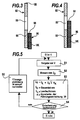
- the display field 84 indicates Reference values RW, represented for example by a reference value bar 86, a desired range of values 88, all of which are desired Value range corresponding values of the pushing force VK an essentially should deliver optimal processing results. Furthermore, the Reference value bar still has a lower undesired value range 90, which is below the desired value range 88 and an upper one unwanted value range 92, which is above the desired value range 88 lies.
- the reference value bar 86 with the desired value range 88 and the Both undesired value ranges 90 and 92 are by preliminary tests to be determined according to the processing parameters available for these and before processing the material bar 32 either the controller 30 can be entered or called in the controller 30.
- the geometry of the guide element 36 and the material of the guide jaws 60 preferably becomes a machining parameter set according to the present invention BPS with the primary for the reference value bar defining parameters and then everyone tries Processing parameter set BPS a specific reference value bar 86 assigned.
- machining parameter sets BPS to set up in the only diameter and material of the respective material bar 32 is received, so that after knowing the diameter and material of the processing material rod 32 of the processing parameter set PBS known and on the basis thereof the reference value bar 86 can be determined.
- the machining parameter sets BPS 1... N and the associated reference value bars 86 1-N are preferably stored in a memory 94, which is assigned to the controller 30, and by entering the diameter and material of the specific material bar 32 as the machining parameter set BPS X via an input field 95 the controller 30 is able to determine the corresponding reference value bar 86 X.
- a measured value bar 96 is displayed in the display field 84, the end 98 represents the actually measured value of the feed force VK.
- the operator knows that the actuating device 70 can be adjusted further, that the feed force VK increases.
- the adjusting force VK can be adjusted by adjusting the setting element 82 increase and a new measurement results, as shown in Fig. 4, then for example, that the end 98 of the measured value bar 96 in the desired Range of values 88.
- the operator can assume that the Guide element 36 for processing the specific material bar 32 is optimally set.
- the advance force VK is determined by Measuring the total current for the sterndrive 22 using the current detection device 80th
- the pushing force VK that is required to pass through the material bar 32 to push the guide element 36 acting on it with the radial force R is not directly proportional to that from the current detector 80 measured total current, but in this total current there are also additional forces that are needed to reduce friction to overcome the movement of the work spindle 12 in the Z direction.
- the feed force VK can then be more precise determine if initially using the current sensing device 80 So-called no-load current IL is measured, which is then used to operate the Sterndrive 22 is required when the material bar 32 is not interacting stands with the guide member 36.
- the guide element 36 for example by delivering the Guide jaws 60, brought into the operative position, so that the guide jaws 60th act with the radial force R on the outer surface 68 of the material rod 32 and then the total current IG is measured with the current detection device, which is required to drive the work spindle 12 in with the sterndrive 22 To move the Z direction when the guide element 36 is effective.
- the feed current IV corresponding to the feed force VK actually corresponds the difference between the total current IG minus the no-load current IL. This allows the display of the pushing force VK through the measuring bar 96 specify that the measured value bar 96 does not correspond to the Total current IG to operate the sterndrive, but according to that Value of the feed current IV determined and shown in the display field 84.
- FIG. 5 A flow chart in such a manual adjustment of the Guide device 34 is shown in FIG. 5.
- the preload force V is given as the initial value with which the setting process starts with a first step S1 and then takes place in one second step S2 a measurement of the total current IG through the guide element 36 of the guide device 34 guided material rod 32.
- the idle current IL is usually known for the respective lathe, so that the pushing force VK are determined in a next step S3 can.
- a next decision step S4 takes place using of the reference value bar 86 and comparison thereof with the measured value bar 96 on the display panel 84 the decision whether the pushing force in desired range of values 88 or not.
- step S5 the guide device 34 via the adjusting element 82 and then takes place measuring the total current again in step S2 and determining the feed force in step S3 with subsequent decision step S4.
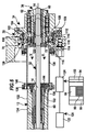
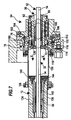
- a second embodiment of a lathe according to the invention shown in Figs. 6 and 7, are those parts that correspond to those of the first embodiment are identical, provided with the same reference numerals, so that with regard to the description thereof the full content of the Comments on the first embodiment are referred to can.
- the adjusting device 70 is not manually operated, but hydraulically.
- the adjusting piston 102 is arranged so that it has an annular Head 108 a rotary bearing 110, preferably an outer bearing ring 112 of the same, acted upon, for example, opposite an inner bearing ring 114 the outer bearing ring 112 is rotatably supported by rolling elements 116.
- the inner bearing ring 114 then in turn carries one opposite Guide tube 62 slidably mounted in the direction of the spindle axis 14 Pressure sleeve 118, on which the adjusting sleeve 72 rests.
- the inlet channels 106 are connected to a hydraulic supply 120, which a pressure generating unit 122 and a control valve 124 with which the pressure of the supply channels 106 supplied Hydraulic medium is adjustable via the controller 30.
- control valve 124 is designed so that it through a specific one that can be predetermined by the controller 30 by means of a control parameter Set pressure P in the cylinder chamber 104, with which then the actuating piston 102 acts on the pressure sleeve 118 via the rotary bearing 110, this pressure P then corresponding to the geometry of the actuating piston 102 leads to a preload force V.
- the pressure sleeve 118 is constantly by a resilient Element 126 acts, which on the one hand in an end region 128 of the guide tube 62 is supported and on the other hand on the pressure sleeve 118 acts in such a way that it counteracts the direction of the biasing force V is moved towards the guide tube 62, unless it is via the actuating piston 102 a force is generated which counteracts that of the resilient element 126 and overcompensated, the preload force V then that of the actuating piston 102 generated force minus the force of the spring elastic Element 126 corresponds.
- the pressure sleeve 118 is indeed in the direction of the spindle axis 14 slidably, but non-rotatably coupled to the guide tube 62 and also with a connecting sleeve 130 rotatably coupled, which starts out extends from the pressure sleeve 118 in the direction of the work spindle 12 and is also non-rotatably connected to it.
- an outer surface 132 of a spindle tube 134 with at least one Flattened 136 provided so that the spindle tube 134 a in cross section Spindle axis 14 is cylindrical, but not rotationally symmetrical Has outer contour.
- the connecting ring 38 slides on the outer surface 132 of the Spindle tube from a front end 140 toward a rear End of the same, as can be seen in the comparison between FIGS. 6 and 7.
- the material rod 32 is fixed in the work spindle 12 by a in the spindle tube 134 arranged collet 142 with jaws 144, which in known manner by moving in the direction of the spindle axis 14 can be placed on the outer surface 68 of the material rod 32.
- the controller 30 is still used to set an optimal feed force VK assigned a pressure control device 150 for the pressure P, with which the Control valve 124 can be actuated via a valve control 152, as in FIG. 8 shown.
- N correlated reference values RW 1 ... N in the memory 94 in the same manner as in the first embodiment with processing parameter sets BPS 1 ... stored for the feed force VK so that upon entering the processing parameters, the controller 30 automatically the appropriate reference values RW for retrieve the pushing force and provide it to the pressure control device 150, as shown in FIG. 9.
- An initial parameter is preferably coupled to the reference values RW AP, which can be predetermined for the pressure control 150, so in a first Step S1 shown in FIG. 10 corresponds to step S1 of the first embodiment corresponds, the control valve 124 an initial pressure for the hydraulic medium sets with which the actuating piston 102 on the pressure sleeve 118 and finally acts on the guide jaws 60, so that this with a corresponding radial force R on the outer surface 68 of the material rod 32 Act.
- step S2 This is followed in a second step S2 by moving the Working spindle 12 in the Z direction and measurement of the total current IG and then in a third step S3 the determination of the feed force VK in the Controller 30 and finally in a step S4 by controller 30 Comparison of the feed force VK with that stored in the memory 94 Reference values RW, for example, also by comparing the pushing force VK with a reference value range determined as optimal.
- the setting process is then either ended or the specification of a new pressure via the pressure control device 150 in a step S5 and then again the measurement subsequently of the total current IG in step S2, the determination of the feed force VK in step S3 and the comparison with the reference values RW in step S4, see above long until the pushing force VK in that in the memory 152 for the special
- the desired value range is as shown in FIG. 10 shown.
- the setting of the feed force VK - as shown in FIG. 11 - In that a radial force is caused by the initial parameter AP R is initially set, which is a feed force VK below the desired reference value range. Then takes place at the end of a setting cycle EZ, formed by steps S2 to S5, an increase in pressure P and thus an increase in the radial force R, which in turn leads to a Increasing the feed force VK leads until the setting cycle in Step S4 is interrupted because it is determined that the feed force VK is within the desired reference range.
- the controller 30 To be able to end the setting process, the controller 30 must be able to to reselect the amount of change in pressure P in each setting cycle.
- step S5a Pressure change done a determination of the size of the to be performed is carried out in step S5a Pressure change done.
- step S4 the difference is already in step S4 between the feed force VK and the desired reference value range the size is determined and then based on this difference in step S5a the change in pressure P is calculated, which is then set in step S5b becomes.
- control valve 124 is only is designed as a pressure control valve, d. H. as a valve, which if a Control signal sets a pressure proportional to this control signal and holds, this can be a change, for example an increase in the pushing force VK, due to external factors, do not prevent, so that for example when inserting a new material bar, which is slightly has larger rod diameter, a new determination of Advancing force VK according to the procedure described advantageous is.
- controller 30 both an adjustment process automatically depending on the event and / or time initiated to adjust the feed force.
- Examples of such events are those which cause the controller 30 to do so can initiate an adjustment process for the feed force VK, a change of parts, d. H. such a displacement of the material bar that after Parting a finished part, another part is processed or also a change of processing, d. H. that after a certain machining cycle, which, for example, heats the material bar As a result, the feed force VK can be adjusted again.
- the setting of the pushing force VK can vary Dimensions of the material bars 32 of a batch, different diameters having sections of the material bars 32 or different thermal states of the material bars 32 always account worn and the subsequent processing always takes place under optimized conditions with regard to the support of the material rod 32 in the guide element 36.
- Another possibility is, initiated by the controller 30, after predeterminable time intervals to adjust the feed force VK, to also, for example, thermal changes in the lathe, which can lead to a change in the pushing force VK, To take into account.
- Time intervals to reset the feed force VK for example thermal changes in the lathe resulting in a change in can lead to tolerances in the area of the guide device 34, To take into account.
- the radial force R is set in a simplified form, and not about the pushing force VK.
- the reference variable for the Adjustment of the guide device 34 is not directly one with the radial force R related size, but the thrust VK, in which in addition to the radial force R, the coefficient of friction between the material bar 32 and the guide jaws 60.
- the feed force VK should be chosen so that the radial force R is as large as possible, but on the other hand the pushing force is just under one Value should be from which the feed of the material rod 32 relative to the guide element 36 in the Z direction affects the work result however
- the use of the feed force VK as a reference variable for the setting the radial force R is advantageous because, depending on the size of the coefficient of friction between the material bar 32 and the guide jaws 60 the maximum possible radial force R is set, which, however, are not so large may that the frictional force is so great that an impairment of the Machining quality due to the impairment of the displacement of the Material rod 32 takes place in the Z direction.
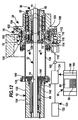
- the current detection device is therefore omitted, on the other hand, as shown in Fig. 12, is between the control valve 124 and the cylinder chamber 104 a pressure measuring device 160 with a Associated pressure sensor 162, with which the pressure P of the hydraulic medium is detectable. Because this pressure P of the hydraulic medium is proportional to the radial force R, the radial force R can be controlled precisely by the pressure P. establish.
- the pressure P serves as a reference variable for setting the radial force R so that, as shown in Fig. 13, the control loop an exact pressure setting for the cylinder chamber 104 delivers, with the determination of the radial force R actually from the pressure sensor 162 measured pressure P in the same way as in the previous embodiments there is the possibility of corresponding processing parameters a reference value range for the pressure P in the cylinder chamber 104 to specify and then with the control valve 124 exactly on this To regulate pressure P.
- the radial support is Material rod 32 can be predetermined with high precision by means of the guide element 60, so that especially when the radial is as precise as possible Support is required, the setting of the guide device 34 according the third embodiment can be done.
- a lathe according to the invention shown in Fig. 14 sits in contrast to the previous ones Embodiments of the spindle housing 16 stationary on the machine frame 10th
- the guide device 34 is arranged on a Z-slide 18 ', which along a Z-guide 20 ′ along that over the workpiece spindle 12 protruding material rod 32 is movable so that the material rod 32nd can be supported at any point by the guide element 36 to with the to be able to precisely process the respective tool 50a.
- a sterndrive 22 ′ is provided, which in the same way as the sterndrive 22 is controllable, its current through the current detection device 80 is detectable.
- the tool carrier 42 not only on the X-slide 52, but the X-guide 54 is in turn seated as a Z-slide 174 a Z guide 176 and is also via a Z drive 178 Control 30 controllable.
- the guide device 34 is preferably designed either as in FIG Connection with the first or the second embodiment described.
- the guide device 34 can be operated in the same way take place as in connection with the first, second or third embodiment described, which in the second and third embodiments connecting sleeve 130 is not present and always a displacement of the guide device instead of the workpiece spindle 12 34 takes place relative to the material rod 32, the whole of which, about project the workpiece spindle 12 in the direction of the tool carrier 42 Length represents the workpiece.
- the fourth embodiment is designed in the same way, as in connection with the preceding exemplary embodiments described so that with regard to the other elements and the functional description reference is made in full to these exemplary embodiments becomes.
Landscapes
- Engineering & Computer Science (AREA)
- Mechanical Engineering (AREA)
- Turning (AREA)
- Machine Tool Units (AREA)
Abstract
Description
Die Erfindung betrifft eine Drehmaschine umfassend ein Maschinengestell, eine am Maschinengestell angeordnete und um eine Spindelachse drehbare Werkstückspindel mit einer Aufnahme für ein Werkstück, mindestens einen Werkzeugträger mit mindestens einem Werkzeug zur Bearbeitung des Werkstücks, eine Führungseinrichtung zur radialen Abstützung des Werkstücks mittels eines Führungselements, welches hierzu mit einer durch eine Stelleinrichtung einstellbaren Radialkraft auf eine Außenfläche des Werkstücks wirkt, wobei die Führungseinrichtung und das Werkstück bei der Bearbeitung desselben relativ zueinander in Richtung der Spindelachse bewegbar sind.The invention relates to a lathe comprising a machine frame, a Workpiece spindle arranged on the machine frame and rotatable about a spindle axis with a holder for a workpiece, at least one tool holder with at least one tool for machining the workpiece, a guide device for radial support of the workpiece of a guide element, which for this purpose with an actuator adjustable radial force acts on an outer surface of the workpiece, the Guide device and the workpiece when machining the same relative are movable relative to each other in the direction of the spindle axis.
Derartige Drehmaschinen sind aus dem Stand der Technik bekannt. Dabei besteht stets das Problem, das Führungselement der Führungseinrichtung mit einer geeigneten Radialkraft einzustellen. Die Einstellung der Radialkraft ist insofern kritisch, als einerseits eine möglichst große Radialkraft eine möglichst gute radiale Abstützung und somit eine möglichst hohe Präzision der Führung in radialer Richtung gewährleistet sein soll, andererseits leidet die Qualität der Bearbeitung, insbesondere die Qualität der Bearbeitung in Richtung der Spindelachse, dann, wenn die Radialkraft ein bestimmtes Maß überschreitet, welches dazu führt, daß die Relativverschiebbarkeit zwischen Werkstück und Führungselement in Richtung der Spindelachse zu schwergängig wird und somit unvorhersehbare "Klemmeffekte" oder "Ruckeffekte" auftreten. Such lathes are known from the prior art. there there is always the problem of having the guide element of the guide device a suitable radial force. The setting of the radial force is critical in so far as on the one hand the greatest possible radial force one as possible good radial support and therefore the highest possible precision of the guidance should be guaranteed in the radial direction, on the other hand, the quality of the Machining, especially the quality of machining towards the Spindle axis, if the radial force exceeds a certain dimension, which leads to the fact that the relative displaceability between workpiece and Guide element in the direction of the spindle axis becomes too stiff and thus unpredictable "pinch effects" or "jerk effects" occur.
Der Erfindung liegt daher die Aufgabe zugrunde, eine Drehmaschine der gattungsgemäßen Art derart zu verbessern, daß die Führungseinrichtung mit möglichst einfachen Maßnahmen möglichst optimal einstellbar ist.The invention is therefore based on the object of a lathe Generic type to improve such that the guide device with measures that are as simple as possible can be optimally adjusted.
Diese Aufgabe wird bei einer Drehmaschine der eingangs beschriebenen Art erfindungsgemäß dadurch gelöst, daß die Drehmaschine mit einer Erfassungseinrichtung für eine Vorschiebekraft, welche erforderlich ist, um das Werkstück und das Führungselement in Richtung der Spindelachse relativ zueinander zu verschieben, versehen ist.This task is carried out in a lathe of the type described above solved according to the invention in that the lathe with a detection device for a feed force that is required to the workpiece and the guide element relative to one another in the direction of the spindle axis move, is provided.
Der Vorteil der erfindungsgemäßen Lösung ist darin zu sehen, daß durch die Erfassung der Vorschiebekraft eine Möglichkeit besteht, die Einstellung des Führungselements, insbesondere die eingestellte Radialkraft, reproduzierbar zu gestalten und gegebenenfalls auch auf einen reproduzierbaren Wert ein- und nachzustellen.The advantage of the solution according to the invention can be seen in the fact that Detection of the pushing force there is a possibility of adjusting the Guide element, in particular the set radial force, reproducible design and, if necessary, also to a reproducible value readjust.
Dabei liefert erfindungsgemäß die Vorschiebekraft ein Maß für die Güte der Einstellung der Führungseinrichtung.According to the invention, the feed force provides a measure of the quality of the Management facility adjustment.
Die Erfassungseinrichtung für die Vorschiebekraft kann dabei in unterschiedlichster Art und Weise wirksam sein.The detection device for the pushing force can be in the most varied of ways Way to be effective.
Beispielsweise wäre es denkbar, die Erfassungseinrichtung unmittelbar im Bereich der Arbeitsspindel oder des Führungselements vorzusehen.For example, it would be conceivable to mount the detection device directly in the Provide area of the work spindle or the guide element.
Besonders einfach ist es jedoch, wenn die Erfassungseinrichtung einem die Relativbewegung zwischen dem Werkstück und dem Führungselement bewirkenden Vorschubantrieb zugeordnet ist. However, it is particularly simple if the detection device detects the Relative movement between the workpiece and the guide element effecting feed drive is assigned.
Eine derartige Zuordnung der Erfassungseinrichtung schafft die Möglichkeit, in einfacher Weise eine die Vorschiebekraft zwischen Werkstück und Führungselement repräsentierende Kraft zu erfassen.Such an assignment of the detection device creates the possibility in a simple way of the feed force between the workpiece and the guide element representative force.
Besonders günstig ist es, wenn die Erfassungseinrichtung die von dem Vorschubantrieb erzeugte Vorschiebekraft erfaßt.It is particularly favorable if the detection device detects that of the Feed drive generated feed force detected.
Diese Vorschiebekraft ist dabei nicht unbedingt direkt proportional zu der Vorschiebekraft, die erforderlich ist, um das Werkstück in Richtung der Spindelachse relativ zum Führungselement zu verschieben. Diese Vorschiebekraft läßt sich jedoch in einfacher Weise, beispielsweise durch Korrekturgrößen, so modifizieren, daß die modifizierte Vorschiebekraft näherungsweise proportional zu der gewünschten Vorschiebekraft zum Verschieben des Werkstücks relativ zum Führungselement ist.This pushing force is not necessarily directly proportional to the pushing force, which is required to move the workpiece in the direction of the spindle axis to move relative to the guide element. This feed force leaves however, in a simple manner, for example by means of correction variables modify that the modified feed force is approximately proportional relative to the desired feed force for moving the workpiece to the guide element.
Beispielsweise wird die erfaßte Vorschiebekraft dadurch korrigiert, daß von dieser die Kräfte subtrahiert werden, die erforderlich sind, um alle mit dem Vorschubantrieb gekoppelten Einrichtungen, wie zum Beispiel die Spindel oder den Reitstock, zu verschieben, ohne Reibung zwischen dem Werkstück und dem Führungselement herrscht, so daß die dadurch ermittelte modifizierte Vorschiebekraft im wesentlichen der durch die Reibung zwischen Werkstück und Führungselement bedingten Vorschiebekraft entspricht.For example, the detected pushing force is corrected by this subtracts the forces that are required to all with the Feed drive coupled devices, such as the spindle or the tailstock to move without friction between the workpiece and the guide element prevails, so that the modified one determined thereby Feeding force essentially that of the friction between the workpiece and guide element conditional pushing force corresponds.
In besonders einfacher Weise läßt sich die Vorschiebekraft dann erfassen, wenn die Erfassungseinrichtung die von dem Vorschubantrieb erzeugte Vorschiebekraft erfaßt. The pushing force can then be recorded in a particularly simple manner, if the detection device generates the one generated by the feed drive Feed force recorded.
Beispielsweise ist in diesem Fall von der tatsächlich gemessenen Vorschiebekraft eine die Reibung in der Vorschubführung repräsentierende Kraft zu subtrahieren.For example, in this case, the actually measured pushing force a force representing the friction in the feed guide subtract.
Besonders einfach läßt sich die Vorschiebekraft bei einem Vorschubantrieb dann erfassen, wenn die Erfassungseinrichtung das Drehmoment des Vorschubantriebs erfaßt.The feed force is particularly simple in the case of a feed drive then detect when the detection device, the torque of the feed drive detected.
Eine derartige Drehmomenterfassung ist beispielsweise mit üblichen Drehmomentsensoren realisierbar.Torque detection of this type is conventional, for example Torque sensors can be implemented.
Noch einfacher ist es jedoch, wenn der Vorschubantrieb ein elektrischer Vorschubantrieb ist und die Erfassungseinrichtung die Stromaufnahme des elektrischen Vorschubantriebs umfaßt, da die Stromaufnahme direkt proportional zu der von dem Vorschubantrieb erzeugten Kraft ist.However, it is even easier if the feed drive is an electric feed drive and the detection device is the current consumption of the electrical Feed drive includes, since the current consumption is directly proportional to the force generated by the feed drive.
Um nun einer Bedienungsperson der Drehmaschine die Einstellung der Führungseinrichtung, insbesondere der Radialkraft des Führungselements, zu erleichtern, ist es besonders günstig, wenn eine Anzeigeeinrichtung zum Anzeigen der Vorschiebekraft vorgesehen ist, da mit einer derartigen Anzeigeeinrichtung in einfacher Weise eine Information des Benutzers über die ermittelte Vorschiebekraft möglich ist.In order for an operator of the lathe to adjust the Guide device, in particular the radial force of the guide element facilitate, it is particularly favorable if a display device for Providing the pushing force is provided because with such a display device information of the user in a simple manner about the determined pushing force is possible.
Die Anzeige kann dabei in unterschiedlichster Art und Weise erfolgen. Beispielsweise wäre eine akustische Anzeige durch die Anzeigeeinrichtung denkbar. The display can be done in many different ways. For example an acoustic display by the display device would be conceivable.
Um dem Bediener jedoch die Möglichkeit zu geben, die Vorschiebekraft einerseits schnell und andererseits möglichst präzise zu erfassen, ist vorzugsweise vorgesehen, daß die Anzeigeeinrichtung die Vorschiebekraft visuell anzeigt.In order to give the operator the possibility, however, of the pushing force on the one hand It is preferable to record quickly and, on the other hand, as precisely as possible provided that the display device visually displays the feed force.
Eine derartige visuelle Anzeige könnte beispielsweise in Zahlenwerten erfolgen. Noch besser ist es jedoch, wenn die Anzeigeeinrichtung die Vorschiebekraft in Form eines Grafikdiagramms anzeigt.Such a visual display could, for example, take the form of numerical values. However, it is even better if the display device has the feed force in Displays the shape of a graphic chart.
Um nun dem Bediener der Drehmaschine die Möglichkeit zu geben, die ermittelte Vorschiebekraft hinsichtlich einer optimalen Einstellung der Führungseinrichtung bewerten zu können, ist vorzugsweise vorgesehen, daß die Anzeigeeinrichtung zusätzlich zur Vorschiebekraft mindestens einen Referenzwert anzeigt, wobei es besonders zweckmäßig ist, wenn der Referenzwert und die Vorschiebekraft gleichzeitig angezeigt werden, so daß durch unmittelbaren Vergleich beider Werte der Bedienungsperson die Qualität der Einstellung der Führungseinrichtung in besonders einfacher Weise vermittelt werden kann.To give the operator of the lathe the opportunity to determined pushing force with regard to an optimal setting of the To be able to evaluate the guide device is preferably provided that the display device in addition to the pushing force at least one Indicates reference value, it being particularly useful if the The reference value and the pushing force are displayed simultaneously, so that quality by directly comparing both values of the operator conveyed the setting of the guide device in a particularly simple manner can be.
Um einen Vergleich der Vorschiebekraft mit dem Referenzwert möglichst einfach zu gestalten, ist vorzugsweise vorgesehen, daß die Anzeigeeinrichtung den Referenzwert und die Vorschiebekraft in demselben Skalen-Maßstab anzeigt.To make a comparison of the feed force with the reference value as simple as possible to design, it is preferably provided that the display device the reference value and the pushing force on the same scale displays.
Auch bei der Anzeige des Referenzwerts hat es sich als vorteilhaft erwiesen, wenn die Anzeigeeinrichtung den mindestens einen Referenzwert visuell, insbesondere in Form eines Grafikdiagramms, anzeigt. When displaying the reference value, it has also proven to be advantageous if the display device visually, in particular the at least one reference value in the form of a graphic diagram.
Da ein einzelner Referenzwert eine optimale Einstellung der Führungseinrichtung nicht leicht erkennbar macht, ist vorzugsweise vorgesehen, daß die Anzeigeeinrichtung den mindestens einen Referenzwert in Form eines Wertebereichs anzeigt. Durch Angabe eines Wertebereichs läßt sich für eine Bedienungsperson schnell und mit ausreichender Präzision die Qualität der Einstellung des Führungselements der Führungseinrichtung erfassen.Since a single reference value an optimal setting of the guide device not easily recognizable, it is preferably provided that the Display device the at least one reference value in the form of a value range displays. By specifying a range of values for a Operator quickly and with sufficient precision the quality of the Detect the setting of the guide element of the guide device.
Besonders günstig ist es, wenn die Anzeigeeinrichtung die Referenzwerte durch einen erwünschten Wertebereich und unerwünschte Wertebereiche anzeigt, so daß für eine Bedienungsperson ein schnell erfaßbarer Vergleich vorgenommen werden kann.It is particularly favorable if the display device contains the reference values by a desired range of values and undesired ranges of values displays, so that for an operator a quickly understandable comparison can be made.
Prinzipiell wäre es denkbar, für jeden Fall entweder einen Referenzwert zu ermitteln oder für alle Fälle einen einzigen Referenzwert als Anhaltspunkt für die Qualität der Einstellung der Führungseinrichtung heranzuziehen. Um jedoch das Führungselement möglichst für den jeweiligen Fall differenziert und andererseits dadurch auch möglichst optimiert einstellen zu können, ist vorzugsweise vorgesehen, daß die Anzeigeeinrichtung den mindestens einen Referenzwert in Abhängigkeit von einem Bearbeitungsparametersatz, umfassend mindestens einen Parameter, ermittelt.In principle, it would be conceivable to either assign a reference value for each case or use a single reference value as a reference for to use the quality of the management's attitude. However, to the guide element differentiates as possible for the respective case and on the other hand, to be able to adjust it as optimally as possible preferably provided that the display device the at least one Reference value depending on a processing parameter set, comprising determined at least one parameter.
Damit besteht die Möglichkeit, fallspezifisch den Referenzwert zu ermitteln und somit dem Benutzer eine optimierte Vorgehensweise nahezulegen.This makes it possible to determine the reference value on a case-by-case basis thus suggesting an optimized procedure to the user.
Um den Referenzwert in Abhängigkeit von dem Bearbeitungsparametersatz jederzeit zur Verfügung stellen zu können, ist vorzugsweise vorgesehen, daß der Bearbeitungsparametersatz und der dazugehörige mindestens eine Referenzwert in einem der Anzeigeeinrichtung zugeordneten Speicher gespeichert sind. Dies erlaubt es, bei Vorliegen der Bearbeitungsparameter in einfacher Weise den Referenzwert aufzurufen.By the reference value depending on the machining parameter set To be able to make available at any time is preferably provided that the processing parameter set and the associated at least one Reference value in a memory assigned to the display device are saved. This allows, if the machining parameters are available in simply call up the reference value.
Besonders günstig läßt sich der Referenzwert dann bestimmen, wenn der Anzeigeeinrichtung eine Eingabeeinrichtung zur Eingabe der Parameter des Bearbeitungsparametersatzes zugeordnet ist, so daß die Bedienungsperson lediglich die Aufgabe hat, bei der jeweiligen Bearbeitung den mindestens einen Parameter des Bearbeitungsparametersatzes zu erfassen und einzugeben, um dann sofort den Referenzwert für eine optimale Vorschiebekraft zur Verfügung zu haben.The reference value can be determined particularly favorably if the Display device an input device for entering the parameters of the Processing parameter set is assigned so that the operator only has the task of at least one in the respective processing To record and enter parameters of the machining parameter set in order to then the reference value for an optimal feed force is immediately available to have.
Prinzipiell wäre es ausreichend, die Stelleinrichtung so auszubilden, daß diese durch unmittelbare Einstellung an der Führungseinrichtung für die gewünschte Radialkraft sorgt.In principle, it would be sufficient to design the actuating device so that it by direct adjustment to the guide device for the desired one Radial force ensures.
Um die Einstellung der Radialkraft jedoch bedienungsfreundlich zu gestalten, ist vorzugsweise vorgesehen, daß die Stelleinrichtung zur Einstellung der Radialkraft durch einen Stellantrieb einstellbar ist.However, to make the setting of the radial force user-friendly, it is preferably provided that the adjusting device for adjusting the Radial force is adjustable by an actuator.
Ein derartiger Stellantrieb könnte so ausgebildet sein, daß er eine Art "ferngesteuerte Einstellung" der Stelleinrichtung zuläßt.Such an actuator could be designed so that it is a kind "Remote controlled setting" of the control device allows.
Eine besonders günstige Lösung sieht jedoch vor, daß der Stellantrieb durch eine Steuereinrichtung ansteuerbar und somit einstellbar ist. Damit besteht über die Steuereinrichtung die Möglichkeit, die Radialkraft einzustellen. A particularly inexpensive solution, however, provides that the actuator by a control device can be controlled and thus adjusted. So that exists the possibility of adjusting the radial force via the control device.
Der Stellantrieb könnte dabei ein elektrischer Antrieb sein. Als besonders geeignet hat es sich erwiesen, wenn der Stellantrieb durch ein unter Druck stehendes Medium betreibbar ist.The actuator could be an electric drive. As special It has proven suitable if the actuator is under pressure standing medium is operable.
Besonders günstig ist es dabei, wenn der Stellantrieb durch Vorgabe des Drucks des Mediums mittels einer von der Steuereinrichtung ansteuerbaren Druckeinstelleinrichtung ansteuerbar ist.It is particularly advantageous if the actuator is set by the Pressure of the medium by means of a controllable by the control device Pressure setting device can be controlled.
Die eingangs genannte Aufgabe wird darüber hinaus auch noch bei einer Drehmaschine der eingangs beschriebenen Art erfindungsgemäß dadurch gelöst, daß eine Radialkraft, mit welcher das Führungselement auf eine Außenseite des Werkstücks wirkt, mittels einer der Führungseinrichtung zugeordneten Steuereinrichtung durch Vergleich einer Führungsgröße mit einem einem mindestens einen Parameter umfassenden Bearbeitungsparametersatz zugeordneten Referenzwert einstellbar ist.The task mentioned at the beginning is also used for a Lathe of the type described in the introduction thereby according to the invention solved that a radial force with which the guide element on a Outside of the workpiece acts by means of one of the guide devices assigned control device by comparing a reference variable with a processing parameter set comprising at least one parameter assigned reference value is adjustable.
Um in einfacher Weise die Führungsgröße zur Einstellung der Radialkraft ermitteln zu können, ist vorzugsweise vorgesehen, daß die Führungsgröße durch eine Erfassungseinrichtung erfaßbar ist.To easily set the command variable for setting the radial force To be able to determine, it is preferably provided that the command variable can be detected by a detection device.
Die Führungsgröße kann dabei unterschiedlich gewählt werden. Besonders günstig ist es, wenn die Führungsgröße eine im Führungselement wirksame Kraft ist, die grundsätzlich an unterschiedlichsten Stellen des Führungselements gemessen werden könnte.The command variable can be chosen differently. Especially It is favorable if the command variable is effective in the guide element Force is basically at the most different places of the guide element could be measured.
Eine günstige Lösung sieht vor, daß die Führungsgröße eine der Radialkraft entsprechende Kraft, beispielsweise eine durch die Radialkraft ausgelöste Reaktionskraft im Führungselement ist, die durch die Erfassungseinrichtung gemessen wird. A cheap solution provides that the command variable is one of the radial force corresponding force, for example a radial force Reactive force in the guide element is caused by the detection device is measured.
Eine besonders einfache Lösung sieht vor, daß die Führungsgröße eine im Stellantrieb wirksame Kraft ist, da sich im Stellantrieb Kräfte besonders einfach erfassen lassen.A particularly simple solution provides that the command variable is an im Actuator effective force is special because there are forces in the actuator just let it be recorded.
Besonders zweckmäßig ist es dabei, wenn die Führungsgröße der im Stellantrieb wirksame Druck des Mediums ist.It is particularly useful if the command variable in the Actuator is effective pressure of the medium.
Alternativ oder ergänzend hierzu sieht eine weitere Lösung vor, daß die Führungsgröße die bei wirksamer Radialkraft zur Relativbewegung zwischen Führungselement und Werkstück erforderliche Vorschiebekraft ist.Alternatively or in addition to this, a further solution provides that the Command variable which, with effective radial force, for the relative movement between Guide element and workpiece is required pushing force.
Die Verwendung der Vorschiebekraft als Führungsgröße hat den Vorteil, daß die Vorschiebekraft nicht nur von der Radialkraft abhängt, sondern gleichzeitig in die Vorschiebekraft auch noch der Reibungskoeffizient zwischen dem Werkstück und dem Führungselement eingeht, der ebenfalls für die Beurteilung des Werts einer sinnvollen Radialkraft erforderlich ist, da der Reibungskoeffizient für die Reibungskraft verantwortlich ist, die dann, wenn sie zu groß ist, die eingangs beschriebenen Präzisionsprobleme bei der Bearbeitung des Werkstücks schafft.The use of the feed force as a reference variable has the advantage that the feed force depends not only on the radial force, but at the same time the coefficient of friction between the workpiece is also included in the feed force and the management element, which is also used for the assessment of the Value of a reasonable radial force is required because of the coefficient of friction is responsible for the frictional force, which if it is too large, the Precision problems in the machining of the workpiece described at the beginning creates.
Aus diesem Grund ist die Vorschiebekraft ein unmittelbares Maß für die Reibungskraft zwischen Werkstück und Führungselement, die letztlich für die Qualität der Bearbeitung entscheidend ist. For this reason, the pushing force is an immediate measure of the Frictional force between the workpiece and the guide element, which is ultimately for the Machining quality is crucial.
Hinsichtlich der Frage, ob ständig oder in Intervallen ein Einstellvorgang für die Radialkraft erfolgt, wurden bislang keine näheren Angaben gemacht. So wäre es beispielsweise denkbar, bei jeder Vorschubbewegung in Richtung der Spindelachse oder auch fortlaufend einen Einstellvorgang für die Radialkraft ablaufen zu lassen.With regard to the question of whether a setting process for the No radial details have been given so far. That would be it is conceivable, for example, with each feed movement in the direction of Spindle axis or continuously an adjustment process for the radial force to expire.
Als besonders vorteilhaft hat es sich jedoch erwiesen, wenn die Steuerung nach einer Aktivierung einen Einstellvorgang für die Radialkraft durchführt, d. h. selbsttätig die Radialkraft einstellt, wobei gemäß dieser Lösung eine ausdrückliche Aktivierung des Einstellvorgangs für die Radialkraft erforderlich ist.However, it has proven to be particularly advantageous if the control performs an adjustment process for the radial force after activation, d. H. automatically sets the radial force, whereby according to this solution explicit activation of the setting process for the radial force required is.
Damit besteht die Möglichkeit, stets innerhalb eines abgeschlossenen Einstellvorgangs die Radialkraft einzustellen.This gives you the option of always within a completed setting process adjust the radial force.
Besonders vorteilhaft ist es dabei, wenn die Steuerung nach Beendigung eines Einstellvorgangs die bei diesem ermittelte Einstellung bis zum nächsten Einstellvorgang aufrecht erhält. Dies hat den Vorteil, daß nicht stets die Einstellung der Radialkraft gewechselt wird, sondern zwischen zwei verschiedenen Einstellvorgängen jeweils die Einstellung gemäß dem vorangegangenen Einstellvorgang erhalten bleibt.It is particularly advantageous if the control after a Setting process the setting determined with this until the next setting process maintains. This has the advantage that not always the setting the radial force is changed, but between two different ones Adjustment processes the setting according to the previous adjustment process preserved.
Ferner ist es zweckmäßig, wenn die Steuereinrichtung nach Durchführung eines Einstellvorgangs den nächsten Einstellvorgang nur nach erneuter Aktivierung durchführt, d. h. nicht selbsttätig weiterarbeitet, sondern nach Beendigung des Einstellvorgangs keine Änderung der Einstellung mehr vornimmt. It is also useful if the control device after implementation of an adjustment process the next adjustment process only after renewed Performs activation, d. H. not continue to work automatically, but after Completion of the setting process no longer changes the setting.
Hinsichtlich der Art der Aktivierung der Steuereinrichtung sind die unterschiedlichsten Lösungsmöglichkeiten denkbar.The most varied of types of activation of the control device Possible solutions conceivable.
Eine vorteilhafte Lösung sieht vor, daß die Steuereinrichtung ereignisabhängig aktivierbar ist, d. h., daß bestimmte Ereignisse im Verlauf eines Arbeitens mit der Drehmaschine zur Aktivierung der Steuereinrichtung für die Einstellung der Radialkraft herangezogen werden.An advantageous solution provides that the control device is event-dependent can be activated, d. that is, certain events in the course of working with the lathe to activate the control device for setting the Radial force can be used.
Beispielsweise ist eine derartige ereignisabhängige Aktivierung der Steuereinrichtung dann möglich, wenn die Steuereinrichtung durch ausgewählte Bearbeitungsschritte der Werkstückbearbeitung aktivierbar ist, d. h. beispielsweise nach dem jeweiligen Bearbeiten eines Werkstückabschnitts eine Aktivierung der Steuereinrichtung erfolgt.Such an event-dependent activation of the control device is, for example possible if the control device is selected by Machining steps of workpiece machining can be activated, d. H. for example after each machining of a workpiece section The control device is activated.
Eine andere Lösung sieht vor, daß die Steuereinrichtung durch Werkstücküberwachungsvorgänge aktivierbar ist, d. h., daß beispielsweise entweder bei Fertigstellung eines vollständig bearbeiteten Teils oder bei einer Vermessung bestimmter Bearbeitungsschritte, insbesondere entsprechend dem Meßergebnis, eine Aktivierung der Steuereinrichtung erfolgt.Another solution provides that the control device through workpiece monitoring processes can be activated, d. that is, for example, either at Completion of a fully machined part or during a survey certain processing steps, especially according to the measurement result, the control device is activated.
Eine andere bevorzugte Lösung sieht vor, daß die Steuereinrichtung bei Arbeitsbeginn aktivierbar ist.Another preferred solution provides that the control device at Start of work can be activated.
Eine andere Möglichkeit, die Steuereinrichtung zu aktivieren, sieht vor, daß diese zeitabhängig aktivierbar ist, d. h., daß eine Aktivierung der Steuereinrichtung nach gewissen Zeitabläufen erfolgt.Another possibility of activating the control device provides that this can be activated depending on the time, d. that is, activation of the controller takes place after certain times.
Beispielsweise läßt sich dies dadurch realisieren, daß die Steuereinrichtung nach festgelegten Laufzeitintervallen der Drehmaschine aktivierbar ist. For example, this can be achieved in that the control device can be activated according to fixed runtime intervals of the lathe.
Hinsichtlich der Art des Einstellvorgangs wurden im Zusammenhang der bisherigen Erläuterung der einzelnen Ausführungsbeispiele keine näheren Angaben gemacht. So könnte ein Einstellvorgang ein ständiges Einstellen der Radialkraft zur Folge haben, das dann zum Referenzwert hin konvergiert.Regarding the type of setting process, the previous No detailed explanation of the individual exemplary embodiments Information provided. So an adjustment process could be a constant adjustment of the Radial force, which then converges towards the reference value.
Besonders vorteilhaft läßt sich jedoch ein Einstellvorgang realisieren, wenn dieser zyklisch erfolgt und mindestens einen Einstellzyklus umfaßt.However, an adjustment process can be realized particularly advantageously if this takes place cyclically and comprises at least one setting cycle.
Vorzugsweise ist vorgesehen, daß während eines Einstellvorgangs so viele Einstellzyklen erfolgen, bis die Führungsgröße innerhalb eines erwünschten Referenzwertebereichs liegt.It is preferably provided that so many during a setting process Adjustment cycles take place until the command variable is within a desired one Reference value range is.
Besonders günstig ist es dabei, wenn die Einstellzyklen so aufeinanderfolgend ablaufen, daß in jedem Einstellzyklus eine Verstellung der Radialkraft um eine bestimmte Schrittweite erfolgt, wobei vorzugsweise die Schrittweite von Einstellzyklus zu Einstellzyklus geringer wird, um damit eine Annäherung an den Referenzwert zu erreichen.It is particularly advantageous if the setting cycles are so consecutive run that an adjustment of the radial force by one in each adjustment cycle certain step size takes place, preferably the step size of setting cycle to the setting cycle becomes smaller in order to approximate the To achieve the reference value.
Beispielsweise ergibt sich dabei die erste Schrittweite aus der Differenz zwischen der tatsächlich ermittelten Führungsgröße und dem Referenzwert und nachfolgend werden diese Differenzen reduziert.For example, the first step size results from the difference between the reference variable actually determined and the reference value and subsequently these differences are reduced.
Hinsichtlich der jeweiligen Ermittlung der Referenzwerte durch einen mindestens einen Parameter umfassenden Bearbeitungsparametersatz wurden bislang keine näheren Angaben gemacht.With regard to the respective determination of the reference values by a machining parameter set comprising at least one parameter No details have been given so far.
So sieht ein besonders vorteilhaftes Ausführungsbeispiel vor, daß der Bearbeitungsparametersatz Materialinformation zum Werkstück umfaßt. A particularly advantageous exemplary embodiment provides that the Machining parameter set includes material information on the workpiece.
Alternativ oder ergänzend ist es auch denkbar, daß der Bearbeitungsparametersatz Geometrieinformation zum unbearbeiteten Werkstück umfaßt.Alternatively or in addition, it is also conceivable that the processing parameter set Includes geometry information on the unmachined workpiece.
Alternativ oder ergänzend ist es ferner denkbar, daß der Bearbeitungsparametersatz Oberflächeninformation zum unbearbeiteten Werkstück umfaßt.Alternatively or additionally, it is also conceivable that the processing parameter set Includes surface information on the unprocessed workpiece.
Weiterhin ist alternativ oder ergänzend vorgesehen, daß der Bearbeitungsparametersatz Bearbeitungsinformation umfaßt.Furthermore, it is alternatively or additionally provided that the processing parameter set Processing information includes.
Alternativ oder ergänzend ist es ferner zweckmäßig, wenn der Bearbeitungsparametersatz Geometrieinformation zum Führungselement umfaßt.Alternatively or additionally, it is also expedient if the processing parameter set Geometry information includes the guide element.
Eine andere alternativ oder ergänzende Lösung sieht vor, daß der Bearbeitungsparametersatz Information zum jeweiligen Führungselement umfaßt.Another alternative or supplementary solution provides that the processing parameter set Includes information about the respective guide element.
Hinsichtlich der Ausbildung der Stelleinrichtung im einzelnen wurden im Zusammenhang mit der bisherigen Erläuterung der einzelnen Ausführungsbeispiele keine näheren Angaben gemacht. So sieht eine besonders günstige Lösung vor, daß die Stelleinrichtung einen mit dem am Werkstück anliegenden Führungselement mitrotierenden Teil und einen sich an einem Gehäuse der Führungseinrichtung abstützenden stationären Teil umfaßt.With regard to the training of the actuating device in detail Connection with the previous explanation of the individual exemplary embodiments no details given. So looks a particularly cheap one Solution before that the actuating device with one of the workpiece Guide element co-rotating part and one on a housing of Guide device supporting stationary part comprises.
Besonders günstig läßt sich die Stelleinrichtung dann mit einem Stellantrieb realisieren, wenn der Stellantrieb in dem stationären Teil der Stelleinrichtung angeordnet ist, da dann der Stellantrieb nicht mitrotieren muß und somit die Versorgung desselben und Verbindung desselben mit der Steuerung konstruktiv besonders günstig realisiert werden kann. The actuating device can then be particularly favorable with an actuator realize when the actuator is in the stationary part of the actuator is arranged, since then the actuator does not have to rotate and thus the Supply of the same and connection of the same with the control constructively can be realized particularly cheap.
Eine Kopplung des stationären Teils und des mitrotierenden Teils der Stelleinrichtung erfolgt vorzugsweise durch ein Drehlager, so daß beispielsweise die vom Stellantrieb erzeugte Kraft in einfacher Weise auf den mitrotierenden Teil der Stelleinrichtung übertragen werden kann.A coupling of the stationary part and the rotating part of the actuating device is preferably carried out by a pivot bearing, so that, for example Force generated by the actuator in a simple manner on the rotating part the actuator can be transferred.
Hinsichtlich der Ausbildung des Stellantriebs sind mehrere Möglichkeiten denkbar. Die konstruktiv einfachste Realisierung, insbesondere dann, wenn der Stellantrieb im stationären Teil der Stelleinrichtung angeordnet ist, sieht vor, daß der Stellantrieb einen durch das Medium beaufschlagbaren Stellkolben umfaßt.With regard to the design of the actuator, several options are conceivable. The structurally simplest implementation, especially if the Actuator is arranged in the stationary part of the actuating device, that the actuator has an actuating piston which can be acted upon by the medium includes.
Darüber hinaus wird die erfindungsgemäße Aufgabe auch durch ein Verfahren zum Betreiben einer Drehmaschine, umfassende eine um eine Spindelachse drehbare Werkstückspindel mit einer Aufnahme für ein Werkstück, mindestens einen Werkzeugträger mit mindestens einem Werkzeug zur Bearbeitung des Werkstücks, eine Führungseinrichtung zur radialen Abstützung des Werkstücks mittels eines Führungselements, welches hierzu mit einer durch eine Stelleinrichtung einstellbaren Radialkraft auf eine Außenfläche des Werkstücks wirkt, wobei die Führungseinrichtung und das Werkstück bei der Bearbeitung desselben relativ zueinander in Richtung der Spindelachse bewegt werden, und erfindungsgemäß eine Radialkraft, mit welcher das Führungselement auf eine Außenseite des Werkstücks wirkt durch Vergleich einer Führungsgröße mit einem einem mindestens einen Parameter umfassenden Bearbeitungsparametersatz zugeordneten Referenzwert eingestellt wird.In addition, the object of the invention is also achieved by a method for operating a lathe, comprising one around a spindle axis rotatable workpiece spindle with a holder for a workpiece, at least a tool holder with at least one tool for machining the Workpiece, a guide device for radial support of the workpiece by means of a guide element, which for this purpose with an actuator adjustable radial force acts on an outer surface of the workpiece, the guide device and the workpiece being machined are moved relative to each other in the direction of the spindle axis, and according to the invention a radial force with which the guide element on a The outside of the workpiece is involved by comparing a reference variable a processing parameter set comprising at least one parameter assigned reference value is set.
Der Vorteil dieses Verfahrens ergibt sich in gleicher Weise wie bei der erfindungsgemäßen Lösung. The advantage of this method is the same as for the solution according to the invention.
Bezüglich weiterer vorteilhafter Ausgestaltungen des erfindungsgemäßen Verfahrens wird auf die voranstehenden Ausführungen zur erfindungsgemäßen Vorrichtung Bezug genommen.With regard to further advantageous refinements of the invention The method is based on the above explanations for the invention Device referred.
Die erfindungsgemäße Führungseinrichtung kann für jede Art der Bearbeitung eingesetzt werden, bei welcher eine Abstützung des Werkstücks in der Nähe des das Werkstück bearbeitenden Werkzeugs erwünscht oder erforderlich ist.The guide device according to the invention can be used for any type of processing are used, in which a support of the workpiece nearby of the tool machining the workpiece is desired or required.
Beispielsweise ist eine derartige Führungseinrichtung als Langdrehführungsbuchse ausgebildet.Such a guide device is, for example, a long turning guide bushing educated.
Eine andere Möglichkeit sieht vor, die Führungseinrichtung als Lünette auszubilden.Another possibility provides for the guide device to be designed as a bezel.
Weitere Merkmale und Vorteile der Erfindung sind Gegenstand der nachfolgenden Beschreibung sowie der zeichnerischen Darstellung einiger Ausführungsbeispiele. In der Zeichnung zeigen:
- Fig. 1
- eine schematische Frontansicht eines ersten Ausführungsbeispiels einer erfindungsgemäßen Drehmaschine;
- Fig. 2
- eine vergrößerte Schnittdarstellung durch eine Führungseinrichtung beim ersten Ausführungsbeispiel der erfindungsgemäßen Drehmaschine;
- Fig. 3
- eine schematische Darstellung einer Anzeige einer Vorschiebekraft in Relation zu Referenzwerten bei Nichterreichen erwünschter Referenzwerte;
- Fig. 4
- eine Darstellung der Vorschiebekraft in Relation zu Referenzwerten ähnlich Fig. 3 bei Erreichen erwünschter Referenzwerte;
- Fig. 5
- ein Ablaufschema bei einer Einstellung der Führungseinrichtung;
- Fig. 6
- einen vergrößerten Schnitt durch Werkstückspindel und Führungseinrichtung eines zweiten Ausführungsbeispiels einer erfindungsgemäßen Drehmaschine;
- Fig. 7
- einen Schnitt ähnlich Fig. 6 bei in Richtung der Führungseinrichtung verschobener Werkstückspindel;
- Fig. 8
- eine schematische Darstellung einzelner Komponenten eines Regelkreises zur selbsttätigen Einstellung der Führungseinrichtung bei dem zweiten Ausführungsbeispiel;
- Fig. 9
- ein Blockdiagramm einzelner Funktionskomponenten der Steuereinrichtung des zweiten Ausführungsbeispiels;
- Fig. 10
- ein Ablaufschema der Einstellung der Führungseinrichtung beim zweiten Ausführungsbeispiel der erfindungsgemäßen Drehmaschine;
- Fig. 11
- eine schematische Darstellung der jeweils eingestellten Werte bei einer Einstellung der Führungseinrichtung entsprechend dem Ablaufschema in Fig. 9;
- Fig. 12
- eine Darstellung ähnlich Fig. 6 eines dritten Ausführungsbeispiels der erfindungsgemäßen Drehmaschine;
- Fig. 13
- eine Darstellung ähnlich Fig. 8 zur Veranschaulichung eines Regelkreises bei der Einstellung der Führungseinrichtung entsprechend dem dritten Ausführungsbeispiel und
- Fig. 14
- eine Darstellung ähnlich Fig. 1 eines vierten Ausführungsbeispiels der erfindungsgemäßen Drehmaschine.
- Fig. 1
- is a schematic front view of a first embodiment of a lathe according to the invention;
- Fig. 2
- an enlarged sectional view through a guide device in the first embodiment of the lathe according to the invention;
- Fig. 3
- a schematic representation of a display of a pushing force in relation to reference values when desired reference values are not reached;
- Fig. 4
- a representation of the pushing force in relation to reference values similar to Figure 3 when reaching desired reference values.
- Fig. 5
- a flow chart for a setting of the guide device;
- Fig. 6
- an enlarged section through the workpiece spindle and guide device of a second embodiment of a lathe according to the invention;
- Fig. 7
- a section similar to Figure 6 with the workpiece spindle displaced in the direction of the guide device;
- Fig. 8
- a schematic representation of individual components of a control loop for automatic adjustment of the guide device in the second embodiment;
- Fig. 9
- a block diagram of individual functional components of the control device of the second embodiment;
- Fig. 10
- a flow chart of the setting of the guide device in the second embodiment of the lathe according to the invention;
- Fig. 11
- a schematic representation of the respectively set values when the guide device is adjusted according to the flow diagram in FIG. 9;
- Fig. 12
- a representation similar to Figure 6 of a third embodiment of the lathe according to the invention.
- Fig. 13
- a representation similar to FIG. 8 to illustrate a control loop when adjusting the guide device according to the third embodiment and
- Fig. 14
- a representation similar to FIG. 1 of a fourth embodiment of the lathe according to the invention.
Ein schematisch in Fig. 1 dargestelltes Ausführungsbeispiel einer erfindungsgemäßen
Drehmaschine umfaßt ein Maschinengestell 10, auf welchem eine
Werkstückspindel 12 angeordnet ist, die um eine Spindelachse 14 drehbar in
einem Spindelgehäuse 16 gelagert ist.An embodiment of an inventive embodiment shown schematically in FIG. 1
Lathe comprises a
Das Spindelgehäuse 16 sitzt seinerseits auf einem Z-Schlitten 18, welcher in
einer parallel zur Spindelachse 14 verlaufenden Z-Richtung auf einer Z-Führung
20 verfahrbar gelagert ist, wobei zum Antrieb des Z-Schlittens 18 ein
Z-Antrieb 22 vorgesehen ist, welcher durch eine Steuerung 30 der Drehmaschine
steuerbar ist.The
In der Arbeitsspindel 16 ist eine Aufnahme für eine ein Werkstück darstellende
Materialstange 32 vorgesehen, welche die Arbeitsspindel 12 in Richtung der
Spindelachse 14 durchsetzt und über die Arbeitsspindel 12 hinausgehend
durch eine beispielsweise als Langdrehführungsbüchse ausgebildete Führungseinrichtung
34 geführt ist, welche mit einem Führungselement 36 die Materialstange
32 unmittelbar angrenzend an einen Arbeitsraum 38 radial zur
Spindelachse 14 abstützt, so daß eine stabile Bearbeitung eines über das
Führungselement 36 in den Arbeitsraum 38 überstehenden Abschnitts 40 der
Materialstange 32 im Arbeitsraum 38 möglich ist, wobei aus diesem Abschnitt
40 dann durch Bearbeitung mehrere Teile entstehen können.In the
Zur Bearbeitung des Werkstücks 32 ist in dem Arbeitsraum 38 ein als Ganzes
mit 42 bezeichneter Werkzeugträger vorgesehen, welcher beispielsweise als
Werkzeugrevolver mit einem Revolvergehäuse 44 und einem Revolverkopf 46
ausgebildet ist, wobei der Revolverkopf 46 um eine Revolverachse 48 gegenüber
dem Revolvergehäuse 44 drehbar ist, um jeweils eines von einer Vielzahl
von am Revolverkopf 46 gehaltenen Werkzeugen 50 in eine Arbeitsstellung zur
Bearbeitung des Werkstücks 40 zu bringen.For machining the
Der Werkzeugrevolver 42 ist dabei seinerseits zumindest auf einem quer zur
Spindelachse 32 verfahrbaren sogenannten X-Schlitten 52 angeordnet, der
seinerseits auf einer X-Führung 54 sitzt, die am Maschinengestell 10 gehalten
ist und durch einen X-Antrieb 56 antreibbar.The
Die Relativverschiebung zwischen dem jeweils in Arbeitsstellung befindlichen
Werkzeug 50A und dem Werkstück 40 erfolgt einerseits in X-Richtung durch
Verschieben des X-Schlittens 52 relativ zur X-Führung 54 mittels des durch die
Steuerung 30 antreibbaren und steuerbaren X-Antriebs 56 sowie in Z-Richtung
durch Verschieben des Spindelgehäuses 16 der Arbeitsspindel 12 in Z-Richtung
durch Bewegen des Z-Schlittens 18 relativ zur Z-Führung 20 mittels des Z-Antriebs
22, angetrieben und gesteuert durch die Steuerung 30, während die
Langdrehführungsbüchse 34 stationär auf dem Maschinengestell 10 montiert
ist, so daß deren Führungselement 36 lediglich um die Spindelachse 14 drehbar
ist, während die Materialstange 32 je nach erforderlicher Z-Position des
Abschnitts 40 relativ zum in Arbeitsstellung stehenden Werkzeug 50A durch
das Führungselement 36 hindurchgeschoben wird.The relative shift between the one in the working
Im einzelnen umfaßt das Führungselement 36 der Langdrehführungsbüchse
34, wie in Fig. 2 dargestellt, Führungsbacken 60, die in einem Führungsrohr 62
in Richtung der Spindelachse 14 verschiebbar gelagert sind und ihrerseits mit
einem Außenkonus 64 an einem Innenkonus 66 des Führungsrohrs 62
anliegen, so daß durch axiale Verschiebung in Richtung der Spindelachse 14,
beispielsweise in Richtung der Arbeitsspindel 12 die Führungsbacken 60 mehr
oder weniger stark in radialer Richtung zur Spindelachse 14 an einer Außenfläche
68 der Materialstange 32 anlegbar sind.In particular, the
Die Verschiebung der Führungsbacken 60 zum radialen Anlegen derselben an
der Außenfläche 68 erfolgt durch eine als Ganzes mit 70 bezeichnete Stelleinrichtung,
die in Fig. 2 lediglich schematisch dargestellt ist. Die Stelleinrichtung
70 ist dabei so ausgebildet, daß sie eine Einstellhülse 72 beaufschlagt, welche
mit den Führungsbacken 60, beispielsweise über eine Gewindeverbindung 74
einstellbar, verbunden ist und somit eine Voreinstellung der Position der
Führungsbacken 60 erlaubt.The displacement of the
Ferner stützt sich die Stelleinrichtung 70 andererseits entweder an dem mit
Drehlagern 76 drehbar in einem Gehäuse 78 der Langdrehführungsbüchse 34
gehaltenen Führungsrohr 62 ab oder unmittelbar an dem Gehäuse 74 der
Langdrehführungsbüchse 34. Furthermore, the
Mit der Stelleinrichtung 70 ist für eine exakte Führung des Werkstücks 40 bei
der Bearbeitung desselben eine ständig wirkende Vorspannkraft V erzeugbar,
welche auf die Einstellhülse 72 wirkt und diese beispielsweise in einer Richtung
von dem Führungsrohr 62 weg beaufschlagt, um die Führungsbacken 60 mit
einer radial zur Spindelachse 14 verlaufenden Radialkraft R an der Außenseite
68 der Materialstange 32 anzulegen und somit diese radial zur Spindelachse 14
präzise zu halten, wobei die Führungsbacken 60 und das Führungsrohr 62 aufgrund
der Drehlager 76 die Möglichkeit haben, in dem Gehäuse 78 der
Langdrehführungsbüchse 34 gemeinsam mit der Materialstange 32 um die
Spindelachse 14 zu rotieren, und zwar in dem Maße in dem durch die Arbeitsspindel
12 eine Drehung der Materialstange 32 erfolgt.The
Die Präzision der Führung der Materialstange 32 in Richtung radial zur Spindelachse
14 durch die Führungsbacken 60 bei der Bearbeitung des Werkstücks 40
hängt von der Radialkraft R ab, d. h., daß bei großer Radialkraft R eine hohe
Präzision der Positionierung des Werkstücks 40 radial zur Spindelachse 14
erreichbar ist, während die Präzision bei geringerer Radialkraft R geringer ist.The precision of guiding the
Andererseits ist jedoch die Verschiebbarkeit der Materialstange 32 relativ zu
den Führungsbacken 60 des Führungselements 36 bei großer Radialkraft R
stärker beeinträchtigt als bei geringer Radialkraft R, insbesondere leidet die
präzise Verschiebbarkeit der Materialstange 32 relativ zu den Führungsbacken
60 unter einer zu großen Radialkraft R, da der stets bei beginnender Verschiebung
der Materialstange 32 relativ zu den Führungsbacken 60 erforderlich
Übergang von der Haftreibung zur Gleitreibung bei hoher Radialkraft zu einem
ruckartigen Verschieben der Materialstange 32 relativ zu den Führungsbacken
führt und somit die Präzision der Positionierung der Materialstange 32 in
Z-Richtung beeinträchtigt wird, worunter wieder die Teilegenauigkeit aufgrund
unpräziser Positionierung des Abschnitts 40 der Materialstange 32 in
Z-Richtung leidet.On the other hand, the displaceability of the
Die Qualität der Bearbeitung des Werkstücks 40 erfordert es daher, die Radialkraft
so groß wie möglich zu wählen, um eine möglichst präzise Führung der
Materialstange 32 radial zur Spindelachse 14 zu erreichen, andererseits aber
die Radialkraft R nicht so groß zu wählen, daß die Qualität der Führung der
Materialstange 32 in Z-Richtung, insbesondere beim Bewegen der Materialstange
32 relativ zum Führungselement 36, beeinträchtigt wird, welche für die
Maßhaltigkeit der Bearbeitung in Z-Richtung maßgebend ist.The quality of the machining of the
Insgesamt ist somit die Radikalkraft so groß zu wählen, daß die Maßhaltigkeit in radialer Richtung ausreicht und die erforderliche Maßhaltigkeit in Z-Richtung erreichbar ist.Overall, the radical force should be chosen so large that the dimensional accuracy sufficient in the radial direction and the required dimensional accuracy in the Z direction is achievable.
Die Verschiebbarkeit in Z-Richtung hängt somit nicht nur von der Radialkraft
R, sondern auch von den Dimensionen der Materialstange 32, der Oberflächenbeschaffenheit
derselben, dem Material derselben sowie von der Oberflächenbeschaffenheit
und Materialbeschaffenheit der Führungsbacken 60 ab.The displaceability in the Z direction does not only depend on the radial force
R, but also on the dimensions of the
Zur Einstellung einer geeigneten Radialkraft R ist es erforderlich, diese zu erfassen.To set a suitable radial force R, it is necessary to to capture.
Bei dem ersten erfindungsgemäßen Ausführungsbeispiel erfolgt nun die
Ermittlung der geeigneten Radialkraft R nicht unmittelbar durch Bestimmung
derselben, sondern durch Bestimmung einer Vorschiebekraft VK, welche
erforderlich ist, um die Materialstange 32 durch die mit der Radialkraft R an
der Außenfläche 68 der Materialstange 32 anliegenden Führungsbacken 60
hindurchzuschieben.In the first exemplary embodiment according to the invention, the
Determination of the suitable radial force R not directly by determination
the same, but by determining a thrust force VK, which
is necessary to the
Diese Vorschiebekraft VK wird von der Steuerung 30 vorzugsweise dadurch
erfaßt, daß diese den beim Verschieben der Arbeitsspindel 12 in Z-Richtung bei
das Führungselement 36 durchsetzender Materialstange 32 und die Radialkraft
R bewirkenden Führungsbacken 60 erforderlichen Strom für den Z-Antrieb 22
erfaßt. Der Strom ist dabei proportional zum Drehmoment des als Servomotor
ausgebildeten Z-Antriebs 22 und das Drehmoment ist seinerseits wiederum
proportional zur Vorschiebekraft VK.This feed force VK is preferably controlled by the
Vorzugsweise erfolgt, wie in Fig. 1 dargestellt, die Strommessung durch eine
Stromerfassungseinrichtung 80, welche Bestandteil der Steuerung 30 ist.As shown in FIG. 1, the current measurement is preferably carried out by a
Im einfachsten Fall ist, wie in Fig. 2 dargestellt, die Stelleinrichtung mit einem
manuell betätigbaren Einstellelement 82 versehen, so daß dadurch die Vorspannkraft
V und somit auch die Radialkraft R, mit welcher die Führungsbacken
60 auf die Materialstange 32 wirken, einstellbar ist.In the simplest case, as shown in Fig. 2, the actuating device with a
manually operable adjusting
Die Vorschiebekraft VK läßt sich durch Verschieben der Arbeitsspindel 12 in
Z-Richtung in der beschriebenen Art und Weise mit der Stromerfassungseinrichtung
80 erfassen und beispielsweise mittels der Steuerung 30 in einem
Anzeigefeld 84 darstellen.The feed force VK can be adjusted by moving the
Um der Bedienungsperson die Möglichkeit zu geben, den im Anzeigefeld 84
dargestellten Wert der Vorschiebekraft VK bewerten zu können und entscheiden
zu können, ob der Wert der Vorschiebekraft VK für die Bearbeitung
der Materialstange geeignet ist oder nicht, gibt das Anzeigefeld 84 durch
Referenzwerte RW, beispielsweise dargestellt durch einen Referenzwertebalken
86, einen erwünschten Wertebereich 88 vor, wobei alle diesem erwünschten
Wertebereich entsprechenden Werte der Vorschiebekraft VK ein im wesentlichen
optimales Bearbeitungsergebnis liefern sollten. Ferner gibt der
Referenzwertebalken noch einen unteren unerwünschten Wertebereich 90 an,
der unterhalb des erwünschten Wertebereichs 88 liegt sowie einen oberen
unerwünschten Wertebereich 92 an, der oberhalb des erwünschten Wertebereichs
88 liegt.In order to give the operator the opportunity to display 84
to be able to evaluate and decide the value of the pushing force VK shown
to be able to determine whether the value of the feed force VK for machining
the material bar is suitable or not, the
Der Referenzwertebalken 86 mit dem erwünschten Wertebereich 88 und den
beiden unerwünschten Wertebereichen 90 und 92 ist dabei durch Vorversuche
entsprechend von bei diesen vorliegenden Bearbeitungsparametern festzulegen
und vor der Bearbeitung der Materialstange 32 entweder der Steuerung
30 eingebbar oder in der Steuerung 30 aufrufbar.The
Da die für die Bearbeitung der Materialstange optimal geeignete Vorschiebekraft
VK vom Material der Materialstange 32, deren Oberflächenbeschaffenheit
und deren Geometrie, insbesondere der Größe, abhängig ist, und außerdem
auch noch von der Art der vorgesehenen Bearbeitung der Materialstange 32,
der Geometrie des Führungselements 36 sowie dem Material der Führungsbacken
60, wird vorzugsweise gemäß der vorliegenden Erfindung ein Bearbeitungsparametersatz
BPS mit den primär für den Referenzwertebalken
bestimmenden Parametern definiert und dann wird durch Verversuche jedem
Bearbeitungsparametersatz BPS ein bestimmter Referenzwertebalken 86
zugeordnet. Because the feed force that is optimally suitable for processing the material bar
VK from the material of the
Im einfachsten Fall kann es ausreichen, Bearbeitungsparametersätze BPS
aufzustellen, in die nur Durchmesser und Material der jeweiligen Materialstange
32 eingeht, so daß nach Kenntnis von Durchmesser und Material der zu
bearbeitenden Materialstange 32 der Bearbeitungsparametersatz PBS bekannt
ist und anhand desselben der diesem zugeordnete Referenzwertebalken 86
ermittelbar ist.In the simplest case, it can be sufficient to use machining parameter sets BPS
to set up in the only diameter and material of the
Vorzugsweise sind die Bearbeitungsparametersätze BPS1...N und die zugeordneten
Referenzwertebalken 861-N in einem Speicher 94, der der Steuerung
30 zugeordnet ist, gespeichert und durch Eingabe von Durchmesser und
Material der spezifischen Materialstange 32 als Bearbeitungsparametersatz
BPSX über ein Eingabefeld 95 ist die Steuerung 30 in der Lage, den entsprechenden
Referenzwertebalken 86X zu ermitteln.The machining parameter sets BPS 1... N and the associated reference value bars 86 1-N are preferably stored in a
Bei Bearbeitung einer spezifischen Materialstange 32 wird nun der für diese
Materialstange 32 ermittelte Referenzwertebalken 86 im Anzeigefeld 84 angezeigt.When processing a
Gleichzeitig wird neben dem Referenzwertebalken 86 in demselben Skalenmaßstab
ein Meßwertebalken 96 im Anzeigefeld 84 angezeigt, dessen Ende 98
den tatsächlich gemessenen Wert der Vorschiebekraft VK repräsentiert.At the same time, next to the
Damit kann die Bedienungsperson in einfacher Weise erkennen, ob die Vorschiebekraft VK bei geeigneten Werten liegt oder nicht.So that the operator can easily recognize whether the Feed force VK is at suitable values or not.
Liegt beispielsweise das Ende 98 des Meßwertebalkens 96 in Höhe des unteren
unerwünschten Bereichs 90, wie in Fig. 3 dargestellt, so weiß die Bedienungsperson,
daß die Stelleinrichtung 70 noch weiter dahingehend zu verstellen ist,
daß die Vorschiebekraft VK ansteigt. For example, the
Durch Verstellen des Einstellelements 82 läßt sich die Vorschiebekraft VK
steigern und eine erneute Messung ergibt, wie in Fig. 4 dargestellt, dann
beispielsweise, daß das Ende 98 des Meßwertebalkens 96 in dem erwünschten
Wertebereich 88 liegt.The adjusting force VK can be adjusted by adjusting the setting
In diesem Fall kann die Bedienungsperson davon ausgehen, daß das
Führungselement 36 für die Bearbeitung der spezifischen Materialstange 32
optimal eingestellt ist.In this case, the operator can assume that the
Die Bestimmung der Vorschiebekraft VK erfolgt im einfachsten Fall durch
Messen des Gesamtstroms für den Z-Antrieb 22 mittels der Stromerfassungseinrichtung
80.In the simplest case, the advance force VK is determined by
Measuring the total current for the
Die Vorschiebekraft VK, die erforderlich ist, um die Materialstange 32 durch
das mit der Radialkraft R auf diese wirkende Führungselement 36 hindurchzuschieben,
ist jedoch nicht direkt proportional dem von der Stromerfassungseinrichtung
80 gemessenen Gesamtstrom, sondern in diesen Gesamtstrom
gehen auch noch zusätzliche Kräfte ein, die benötigt werden, um Reibung bei
der Bewegung der Arbeitsspindel 12 in Z-Richtung zu überwinden.The pushing force VK that is required to pass through the
Aus diesem Grund läßt sich die Vorschiebekraft VK noch präziser dann
bestimmen, wenn zunächst mit der Stromerfassungseinrichtung 80 ein
sogenannter Leerlaufstrom IL gemessen wird, der dann zum Betreiben des
Z-Antriebs 22 erforderlich ist, wenn die Materialstange 32 nicht in Wechselwirkung
mit dem Führungselement 36 steht. For this reason, the feed force VK can then be more precise
determine if initially using the
Anschließend wird das Führungselement 36, beispielsweise durch Zustellen der
Führungsbacken 60, in Wirkstellung gebracht, so daß die Führungsbacken 60
mit der Radialkraft R auf die Außenfläche 68 der Materialstange 32 wirken und
dann wird der Gesamtstrom IG mit der Stromerfassungseinrichtung gemessen,
welcher erforderlich ist, um mit dem Z-Antrieb 22 die Arbeitsspindel 12 in
Z-Richtung bei wirksamem Führungselement 36 zu verschieben.Then the
Der tatsächlich der Vorschiebekraft VK entsprechende Vorschubstrom IV entspricht
dabei der Differenz des Gesamtstroms IG abzüglich des Leerlaufstroms
IL. Damit läßt sich die Anzeige der Vorschiebekraft VK durch den Meßbalken
96 dadurch präzisieren, daß der Meßwertebalken 96 nicht entsprechend dem
Gesamtstrom IG zum Betreiben des Z-Antriebs, sondern entsprechend dem
Wert des Vorschubstroms IV ermittelt und im Anzeigefeld 84 dargestellt wird.The feed current IV corresponding to the feed force VK actually corresponds
the difference between the total current IG minus the no-load current
IL. This allows the display of the pushing force VK through the measuring
Ein Ablaufdiagramm bei einer derartigen manuellen Nachstellung der
Führungseinrichtung 34 ist in Fig. 5 dargestellt.A flow chart in such a manual adjustment of the
Beispielsweise wird nach einem manuellen Start des Einstellvorgangs zunächst
ein entweder fest eingestellter oder auch eventuell bereits durch den Bearbeitungsparametersatz
definierter oder einfach des bisher verwendete Wert
der Vorspannkraft V als Anfangswert vorgegeben, mit welchem der Einstellvorgang
mit einem ersten Schritt S1 beginnt und danach erfolgt in einem
zweiten Schritt S2 ein Messen des Gesamtstroms IG bei durch das Führungselement
36 der Führungseinrichtung 34 geführter Materialstange 32.For example, after a manual start of the setting process
a set either permanently or possibly already through the processing parameter set
defined or simply the previously used value
the preload force V is given as the initial value with which the setting process
starts with a first step S1 and then takes place in one
second step S2 a measurement of the total current IG through the
Üblicherweise ist der Leerlaufstrom IL für die jeweilige Drehmaschine bekannt, so daß in einem nächsten Schritt S3 die Vorschiebekraft VK ermittelt werden kann. The idle current IL is usually known for the respective lathe, so that the pushing force VK are determined in a next step S3 can.
In einem nächsten Entscheidungsschritt S4 erfolgt nun unter Heranziehung
des Referenzwertebalkens 86 und Vergleich desselben mit dem Meßwertebalken
96 auf dem Anzeigefeld 84 die Entscheidung, ob die Vorschiebekraft im
erwünschten Wertebereich 88 liegt oder nicht.In a next decision step S4 takes place using
of the
Ist dies nicht der Fall, so erfolgt in einem Schritt S5 ein manuelles Nachstellen
der Führungseinrichtung 34 über das Einstellelement 82 und dann erfolgt ein
erneutes Messen des Gesamtstroms im Schritt S2 und die Ermittlung der Vorschiebekraft
in Schritt S3 mit nachfolgendem Entscheidungsschritt S4.If this is not the case, manual adjustment is carried out in a step S5
the
Dieser Vorgang wird so lange zyklisch durchgeführt, bis das Ende 98 des
Meßwertebalkens 96 einen Wert der Vorschiebekraft VK anzeigt, der im
erwünschten Wertebereich 88 des Referenzwertebalkens 86 liegt. Damit ist der
Einstellvorgang beendet.This process is carried out cyclically until the
Bei einem zweiten Ausführungsbeispiel einer erfindungsgemäßen Drehmaschine, dargestellt in Fig. 6 und 7, sind diejenigen Teile, die mit denen des ersten Ausführungsbeispiels identisch sind, mit denselben Bezugszeichen versehen, so daß hinsichtlich der Beschreibung derselben vollinhaltlich auf die Ausführungen zum ersten Ausführungsbeispiel Bezug genommen werden kann.In a second embodiment of a lathe according to the invention, shown in Figs. 6 and 7, are those parts that correspond to those of the the first embodiment are identical, provided with the same reference numerals, so that with regard to the description thereof the full content of the Comments on the first embodiment are referred to can.
Im Gegensatz zum ersten Ausführungsbeispiel ist die Stelleinrichtung 70 nicht
manuell betätigbar, sondern hydraulisch. In contrast to the first exemplary embodiment, the adjusting
Hierzu ist in der Stelleinrichtung 70 ein als Ganzes mit 100 bezeichneter
hydraulischer Stellantrieb vorgesehen, der einen im Gehäuse 78 der
Führungseinrichtung 34 abgedichtet gelagerten ringförmig ausgebildeten
Stellkolben 102 umfaßt, welcher durch einer Zylinderkammer 104 über
Zulaufkanäle 106 im Gehäuse 78 zugeführtes Hydraulikmedium betätigbar ist.For this purpose, one is designated as a whole by 100 in the adjusting
Der Stellkolben 102 ist dabei so angeordnet, daß er mit einem ringförmigen
Kopf 108 ein Drehlager 110, vorzugsweise einen äußeren Lagerring 112 desselben,
beaufschlagt, während beispielsweise ein innerer Lagerring 114 gegenüber
dem äußeren Lagerring 112 durch Wälzkörper 116 drehbar gelagert ist.The
Der innere Lagerring 114 trägt dann seinerseits eine gegenüber dem
Führungsrohr 62 in Richtung der Spindelachse 14 verschiebbar gelagerte
Druckhülse 118, auf welcher die Einstellhülse 72 aufliegt.The
Mit der Druckhülse 118 besteht nun die Möglichkeit, die Einstellhülse 72 mit
der Vorspannkraft V zu beaufschlagen, und zwar im mit dem Führungsrohr 62
mitrotierenden System, während der Stellkolben 102 von der im rotierenden
System mit dem Führungsrohr 62 mitrotierenden Druckhülse 118 durch das
Drehlager 110 rotatorisch entkoppelt ist und somit der Stellkolben 102 nicht
rotierend im Gehäuse 78 der Führungseinrichtung angeordnet sein kann und
lediglich eine Bewegung parallel zur Spindelachse 14 ausführt.With the
Ferner sind die Zulaufkanäle 106 mit einer Hydraulikversorgung 120 verbunden,
welche eine Druckerzeugungseinheit 122 und ein Steuerventil 124
umfaßt, mit welchem der Druck des den Zulaufkanälen 106 zugeführten
Hydraulikmediums über die Steuerung 30 einstellbar ist. In addition, the
Vorzugsweise ist dabei das Steuerventil 124 so ausgebildet, daß es durch
einen bestimmten, von der Steuerung 30 durch einen Steuerparameter vorgebbaren
Druck P in der Zylinderkammer 104 einzustellen, mit welchem dann
der Stellkolben 102 über das Drehlager 110 die Druckhülse 118 beaufschlagt,
wobei dieser Druck P entsprechend der Geometrie des Stellkolbens 102 dann
zu einer Vorspannkraft V führt.Preferably, the
Um sicherzustellen, daß bei Reduzierung des Drucks in der Zylinderkammer
104 die Vorspannkraft V und insbesondere auch die Radialkraft R dann entsprechend
abnehmen, ist die Druckhülse 118 ständig durch ein federelastisches
Element 126 beaufschlagt, welches einerseits in einem Endbereich
128 des Führungsrohrs 62 abgestützt ist und andererseits auf die Druckhülse
118 dergestalt wirkt, daß diese entgegen der Richtung der Vorspannkraft V
zum Führungsrohr 62 hin bewegt wird, sofern nicht über den Stellkolben 102
eine Kraft erzeugt wird, die der des federelastischen Elements 126 entgegenwirkt
und überkompensiert, wobei die Vorspannkraft V dann der vom Stellkolben
102 erzeugten Kraft abzüglich der Kraftwirkung des federelastischen
Elements 126 entspricht.To ensure that when reducing the pressure in the
Darüber hinaus ist die Druckhülse 118 zwar in Richtung der Spindelachse 14
verschieblich, jedoch drehfest mit dem Führungsrohr 62 gekoppelt und außerdem
mit einer Verbindungshülse 130 drehfest gekoppelt, welche sich ausgehend
von der Druckhülse 118 in Richtung der Arbeitsspindel 12 erstreckt
und mit dieser ebenfalls drehfest verbunden ist.In addition, the
Hierzu ist eine Außenfläche 132 eines Spindelrohrs 134 mit mindestens einer
Abflachung 136 versehen, so daß das Spindelrohr 134 eine im Querschnitt zur
Spindelachse 14 zwar zylindrisch verlaufende, jedoch nicht rotationssymmetrische
Außenkontur aufweist. For this purpose, an
Ein auf dieser Außenfläche 132 zumindest im Bereich der Abflachung 136 und
dieser gegenüberliegend anliegender Verbindungsring 138 ist somit auf der
Außenfläche 132 des Spindelrohrs 134 in Richtung der Spindelachse 14 verschiebbar,
jedoch nicht relativ zum Spindelrohr 134 drehbar. Mit diesem Verbindungsring
138 ist die Verbindungshülse 130 fest verbunden und somit
erfolgt eine drehfeste Verbindung zwischen dem Spindelrohr 134 über den
Verbindungsring 138, die Verbindungshülse 130 und die Druckhülse 118 mit
dem Führungsrohr 62, so daß sich dieses unabhängig von der Frage, ob die
Materialstange 32 durch die Führungsbacken 60 eingespannt ist oder nicht,
drehgekoppelt mit dem Spindelrohr 134 um die Spindelachse 14 dreht.One on this
Andererseits besteht die Möglichkeit, durch Vorschub in Z-Richtung das
Spindelrohr 134 in die Verbindungshülse 130 in Richtung des Führungselements
36 einzuschieben, um den Vorschub der Materialstange 32 durch das
Führungselement 36 hindurch in den Arbeitsraum 38 realisieren zu können.On the other hand, it is possible to do this by feeding in the Z
In diesem Fall gleitet der Verbindungsring 38 auf der Außenfläche 132 des
Spindelrohrs von einem vorderen Ende 140 weg in Richtung eines hinteren
Endes derselben, wie im Vergleich zwischen Fig. 6 und Fig. 7 erkennbar ist.In this case, the connecting
Die Fixierung der Materialstange 32 in der Arbeitsspindel 12 erfolgt durch eine
im Spindelrohr 134 angeordnete Spannzange 142 mit Spannbacken 144, die in
bekannter Art und Weise durch Verschieben in Richtung der Spindelachse 14
an der Außenfläche 68 der Materialstange 32 anlegbar sind. The
Zur Einstellung einer optimalen Vorschiebekraft VK ist der Steuerung 30 noch
eine Drucksteuereinrichtung 150 für den Druck P zugeordnet, mit welcher das
Steuerventil 124 über eine Ventilansteuerung 152 betätigbar ist, wie in Fig. 8
dargestellt.The
Ferner sind in dem Speicher 94 in gleicher Weise wie beim ersten Ausführungsbeispiel
mit Bearbeitungsparametersätzen BPS1...N korrelierte
Referenzwerte RW1...N für die Vorschiebekraft VK abgespeichert, so daß bei
Eingabe der Bearbeitungsparameter die Steuerung 30 selbsttätig die
geeigneten Referenzwerte RW für die Vorschiebekraft abrufen und der Drucksteuereinrichtung
150 zur Verfügung stellen kann, wie in Fig. 9 dargestellt.Further, N correlated reference values RW 1 ... N in the
Gekoppelt mit den Referenzwerten RW ist vorzugsweise ein Anfangsparameter
AP, welcher der Druckansteuerung 150 vorgebbar ist, damit in einem ersten
Schritt S1, dargestellt in Fig. 10, der dem Schritt S1 des ersten Ausführungsbeispiels
entspricht, das Steuerventil 124 einen Anfangsdruck für das Hydraulikmedium
einstellt, mit welchem dann der Stellkolben 102 auf die Druckhülse
118 und schließlich auf die Führungsbacken 60 wirkt, so daß diese mit einer
entsprechenden Radialkraft R auf die Außenfläche 68 der Materialstange 32
wirken.An initial parameter is preferably coupled to the reference values RW
AP, which can be predetermined for the
Nachfolgend erfolgt in einem zweiten Schritt S2 durch Verschieben der
Arbeitsspindel 12 in Z-Richtung und Messung des Gesamtstroms IG und dann
in einem dritten Schritt S3 die Ermittlung der Vorschiebekraft VK in der
Steuerung 30 und schließlich in einem Schritt S4 durch die Steuerung 30 ein
Vergleich der Vorschiebekraft VK mit den in dem Speicher 94 abgelegten
Referenzwerten RW beispielsweise ebenfalls durch Vergleich der Vorschiebekraft
VK mit einem als optimal bestimmten Referenzwertebereich. This is followed in a second step S2 by moving the
Entsprechend diesem Vergleich erfolgt dann entweder die Beendigung des Einstellvorgangs
oder die Vorgabe eines neuen Drucks über die Drucksteuereinrichtung
150 in einem Schritt S5 und dann nachfolgend erneut die Messung
des Gesamtstroms IG im Schritt S2, die Bestimmung der Vorschiebekraft VK
im Schritt S3 und der Vergleich mit den Referenzwerten RW im Schritt S4, so
lange bis die Vorschiebekraft VK in dem in dem Speicher 152 für die spezielle
Materialstange niedergelegten erwünschten Wertebereich liegt, wie in Fig. 10
dargestellt.According to this comparison, the setting process is then either ended
or the specification of a new pressure via the
Beispielsweise kann das Einstellen der Vorschiebekraft VK - wie in Fig. 11 dargestellt - dadurch erfolgen, daß durch den Anfangsparameter AP eine Radialkraft R zunächst eingestellt wird, die eine Vorschiebekraft VK unterhalb des erwünschten Referenzwertebereichs liegt. Dann erfolgt am Ende eines Einstellzyklus EZ, gebildet durch die Schritte S2 bis S5, eine Erhöhung des Drucks P und somit eine Vergrößerung der Radialkraft R, die wiederum zu einer Erhöhung der Vorschiebekraft VK führt, so lange bis der Einstellzyklus in Schritt S4 unterbrochen wird, da festgestellt wird, daß die Vorschiebekraft VK innerhalb des erwünschten Referenzwertebereichs liegt.For example, the setting of the feed force VK - as shown in FIG. 11 - In that a radial force is caused by the initial parameter AP R is initially set, which is a feed force VK below the desired reference value range. Then takes place at the end of a setting cycle EZ, formed by steps S2 to S5, an increase in pressure P and thus an increase in the radial force R, which in turn leads to a Increasing the feed force VK leads until the setting cycle in Step S4 is interrupted because it is determined that the feed force VK is within the desired reference range.
Um möglichst effizient mit möglichst geringer Anzahl von Einstellzyklen EZ den
Einstellvorgang beenden zu können, muß die Steuerung 30 in der Lage sein,
die Größe der Änderung des Drucks P in jedem Einstellzyklus neu zu wählen.To EZ as efficiently as possible with the smallest possible number of setting cycles
To be able to end the setting process, the
Hierzu wird im Schritt S5a eine Ermittlung der Größe der vorzunehmenden Änderung des Drucks durchgeführt. For this purpose, a determination of the size of the to be performed is carried out in step S5a Pressure change done.
Dies ist beispielsweise dadurch möglich, daß im Schritt S4 bereits die Differenz zwischen der Vorschiebekraft VK und dem gewünschten Referenzwertebereich ermittelt wird und auf der Basis dieser Differenz dann im Schritt S5a die Größe der Änderung des Drucks P berechnet wird, die dann im Schritt S5b eingestellt wird.This is possible, for example, in that the difference is already in step S4 between the feed force VK and the desired reference value range the size is determined and then based on this difference in step S5a the change in pressure P is calculated, which is then set in step S5b becomes.
Es ist aber auch denkbar, bei jedem Einstellvorgang mit dem ersten Einstellzyklus beginnend jedem Einstellzyklus einen Änderungsbetrag fest vorzugeben, der vorzugsweise von Einstellzyklus EZ zu Einstellzyklus EZ kleiner wird.However, it is also conceivable for the first adjustment cycle in each adjustment process to specify a change amount starting with each adjustment cycle, which is preferably smaller from setting cycle EZ to setting cycle EZ becomes.
Besonders günstig ist es, wenn bei dem zweiten Ausführungsbeispiel nicht nur
in dem Speicher 94 als Bearbeitungsparametersatz BPS Daten zu Materialien
und Durchmesser der Materialstangen, sondern auch verschiedener Führungseinrichtungen
ablegbar sind, so daß zur jeweiligen Paarung von Führungseinrichtung
34 und Materialstange 32 ein gewünschter Referenzwertebereich
RW für die Vorschiebekraft VK zur Verfügung steht.It is particularly favorable if not only in the second embodiment
in the
Obwohl bei dem zweiten Ausführungsbeispiel ist das Steuerventil 124 lediglich
als Druckregelventil ausgebildet ist, d. h. als Ventil, welches bei Vorgabe eines
Steuersignals einen in diesem Steuersignal proportionalen Druck einstellt und
hält, kann dieses eine Veränderung, beispielsweise Vergrößerung der Vorschiebekraft
VK, bedingt durch äußere Einflußgrößen, nicht verhindern, so daß
beispielsweise beim Einsetzen einer neuen Materialstange, die einen geringfügig
größeren Stangendurchmesser aufweist, eine erneute Bestimmung der
Vorschiebekraft VK entsprechend der beschriebenen Vorgehensweise vorteilhaft
ist. Although in the second embodiment, the
Aus diesem Grund ist vorzugsweise vorgesehen, daß die Steuerung 30 sowohl
ereignisabhängig und/oder auch zeitabhängig selbsttätig einen Einstellvorgang
zur Einstellung der Vorschiebekraft initiiert.For this reason, it is preferably provided that the
Beispielsweise sind derartige Ereignisse, welche die Steuerung 30 dazu veranlassen
können, einen Einstellvorgang für die Vorschiebekraft VK zu initiieren,
ein Teilewechsel, d. h. ein derartiges Verschieben der Materialstange, daß nach
Abstechen eines fertig bearbeiteten Teils ein weiteres Teil bearbeitet wird oder
auch ein Bearbeitungswechsel, d. h. daß nach einem bestimmten Bearbeitungszyklus,
welcher beispielsweise eine Erwärmung der Materialstange zur
Folge haben kann, eine erneute Einstellung der Vorschiebekraft VK erfolgt.Examples of such events are those which cause the
Mit dieser entsprechend bestimmten Ereignissen initiierten stets erneut
erfolgenden Einstellung der Vorschiebekraft VK kann unterschiedlichen
Dimensionen der Materialstangen 32 einer Charge, unterschiedliche Durchmesser
aufweisenden Abschnitten der Materialstangen 32 oder auch unterschiedlichen
thermischen Zuständen der Materialstangen 32 stets Rechnung
getragen werden und die nachfolgende Bearbeitung erfolgt stets unter
optimierten Bedingungen hinsichtlich der Abstützung der Materialstange 32 in
dem Führungselement 36.With this corresponding certain events always initiated again
The setting of the pushing force VK can vary
Dimensions of the material bars 32 of a batch, different diameters
having sections of the material bars 32 or different
thermal states of the material bars 32 always account
worn and the subsequent processing always takes place under
optimized conditions with regard to the support of the
Eine andere Möglichkeit besteht darin, initiiert durch die Steuerung 30, nach
vorgebbaren Zeitabständen eine Einstellung der Vorschiebekraft VK durchzuführen,
um auch beispielsweise thermischen Veränderungen der Drehmaschine,
die zu einer Änderung der Vorschiebekraft VK führen können,
Rechnung zu tragen. Another possibility is, initiated by the
Beispielsweise ist es denkbar, bei Beginn einer Bearbeitung einer Serie von
Materialstangen 32 mit der erfindungsgemäßen Drehmaschine nach festgelegten
Zeitintervallen die Vorschiebekraft VK neu einzustellen, um beispielsweise
thermischen Veränderungen der Drehmaschine, die zu einer Änderung in
den Toleranzen im Bereich der Führungseinrichtung 34 führen können,
Rechnung zu tragen.For example, it is conceivable to start processing a series of
Material bars 32 according to the lathe according to the invention
Time intervals to reset the feed force VK, for example
thermal changes in the lathe resulting in a change in
can lead to tolerances in the area of the
Bei einem dritten Ausführungsbeispiel einer erfindungsgemäßen Drehmaschine erfolgt die Einstellung der Radialkraft R in vereinfachter Form, und zwar nicht über die Vorschiebekraft VK.In a third embodiment of a lathe according to the invention the radial force R is set in a simplified form, and not about the pushing force VK.
Bei dem ersten und zweiten Ausführungsbeispiel ist die Führungsgröße für die
Einstellung der Führungseinrichtung 34 nicht unmittelbar eine mit der Radialkraft
R zusammenhängende Größe, sondern die Vorschiebekraft VK, in welche
zusätzlich zur Radialkraft R der Reibungskoeffizient zwischen der Materialstange
32 und den Führungsbacken 60 eingeht.In the first and second exemplary embodiments, the reference variable for the
Adjustment of the
Dies führt dazu, daß bei Einstellung der Führungseinrichtung 34 auf der Basis
der Vorschiebekraft VK als Führungsgröße die Radialkraft R unterschiedlich
groß sein kann, sofern der Reibungskoeffizient sich entweder innerhalb derselben
Materialstange oder beispielsweise auch von Materialstange zu
Materialstange verändert, so daß daraus zwangsläufig auch eine unterschiedlich
gute radiale Abstützung der Materialstange 32 aufgrund der
variierenden Radialkraft R resultiert.This leads to the fact that when the
In allen denen Fällen, in denen die Radialkraft R möglichst groß sein soll und
einerseits die Vorschiebekraft VK so gewählt werden sollte, daß die Radialkraft
R möglichst groß ist, andererseits aber die Vorschiebekraft knapp unter einem
Wert liegen sollte, ab welchem der Vorschub der Materialstange 32 relativ zu
dem Führungselement 36 in Z-Richtung das Arbeitsergebnis beeinträchtigt, ist
jedoch das Heranziehen der Vorschiebekraft VK als Führungsgröße für die Einstellung
der Radialkraft R vorteilhaft, da je nach Größe des Reibungskoeffizienten
zwischen der Materialstange 32 und den Führungsbacken 60 die
maximal mögliche Radialkraft R eingestellt wird, die jedoch nicht so groß sein
darf, daß die Reibungskraft so groß ist, daß eine Beeinträchtigung der
Bearbeitungsqualität aufgrund der Beeinträchtung der Verschiebung der
Materialstange 32 in Z-Richtung erfolgt.In all those cases in which the radial force R should be as large as possible and
on the one hand, the feed force VK should be chosen so that the radial force
R is as large as possible, but on the other hand the pushing force is just under one
Value should be from which the feed of the
Bei dem dritten Ausführungsbeispiel, welches auf dem Aufbau gemäß dem
zweiten Ausführungsbeispiel basiert, entfällt daher die Stromerfassungseinrichtung,
dagegen ist, wie in Fig. 12 dargestellt, zwischen dem Steuerventil
124 und der Zylinderkammer 104 eine Druckmeßeinrichtung 160 mit einem
Drucksensor 162 zugeordnet, mit welcher der Druck P des Hydraulikmediums
erfaßbar ist. Da dieser Druck P des Hydraulikmediums proportional zur Radialkraft
R ist, läßt sich über eine exakte Regelung des Drucks P die Radialkraft R
festlegen.In the third embodiment, which is based on the structure according to
based on the second exemplary embodiment, the current detection device is therefore omitted,
on the other hand, as shown in Fig. 12, is between the
Somit dient bei dem dritten Ausführungsbeispiel der Druck P als Führungsgröße
für die Einstellung der Radialkraft R, so daß, wie in Fig. 13 dargestellt,
der Regelkreis eine exakte Druckeinstellung für die Zylinderkammer 104
liefert, wobei zur Ermittlung der Radialkraft R der tatsächlich vom Drucksensor
162 gemessene Druck P in gleicher Weise wie bei den vorangehenden Ausführungsbeispielen
die Möglichkeit besteht, entsprechenden Bearbeitungsparametern
einen Referenzwertebereich für den Druck P in der Zylinderkammer
104 vorzugeben und dann mit dem Steuerventil 124 exakt auf diesen
Druck P zu regeln. Thus, in the third exemplary embodiment, the pressure P serves as a reference variable
for setting the radial force R so that, as shown in Fig. 13,
the control loop an exact pressure setting for the
Da der Druck P in der Zylinderkammer 104 direkt proportional zur Radialkraft
R ist, kann der Reibungskoeffizient zwischen den jeweiligen Materialstangen 32
und den Führungsbacken 60 nur rechnerisch berücksichtigt werden, so daß die
benötigte Vorschiebekraft VK entsprechend der Streubreite im Reibungskoeffizienten
um den rechnerisch berücksichtigten Reibungskoeffizienten
zwischen der Materialstange 32 und den Führungsbacken 60 schwankt.Because the pressure P in the
Allerdings ist bei diesem Ausführungsbeispiel die radiale Abstützung der
Materialstange 32 mittels des Führungselements 60 mit hoher Präzision vorgebbar,
so daß insbesondere dann, wenn eine möglichst präzise radiale
Abstützung erforderlich ist, die Einstellung der Führungseinrichtung 34 gemäß
dem dritten Ausführungsbeispiel erfolgen kann.However, in this embodiment, the radial support is
Es ist aber auch denkbar, bei einer Drehmaschine sowohl eine Einstellung
gemäß dem zweiten Ausführungsbeispiel oder dem dritten Ausführungsbeispiel
oder eine Kombination derselben vorzusehen, um eine möglichst optimale
Führung der Materialstange 32 in der Führungseinrichtung 34 zu erzielen.However, it is also conceivable to use both settings on a lathe
according to the second embodiment or the third embodiment
or a combination thereof to provide the best possible
To achieve guidance of the
Bei einem vierten Ausführungsbeispiel einer erfindungsgemäßen Drehmaschine,
dargestellt in Fig. 14 sitzt im Gegensatz zu den vorangegangenen
Ausführungsbeispielen das Spindelgehäuse 16 stationär auf dem Maschinengestell
10.In a fourth embodiment of a lathe according to the invention,
shown in Fig. 14 sits in contrast to the previous ones
Embodiments of the
Dagegen ist die Führungseinrichtung 34 auf einem Z-Schlitten 18' angeordnet,
welcher längs einer Z-Führung 20' längs der über die Werkstückspindel 12
überstehenden Materialstange 32 verfahrbar ist, so daß die Materialstange 32
an beliebiger Stelle durch das Führungselement 36 abstützbar ist, um mit dem
jeweiligen Werkzeug 50a präzise bearbeiten zu können. In contrast, the
Zum Verschieben der Führungseinrichtung 34 mittels des Z-Schlittens 18' ist
ein Z-Antrieb 22' vorgesehen, welcher in gleicher Weise wie der Z-Antrieb 22
ansteuerbar ist, wobei dessen Strom durch die Stromerfassungseinrichtung 80
erfaßbar ist.To move the
Ferner sitzt bei dem vierten Ausführungsbeispiel der erfindungsgemäßen
Drehmaschine der Werkzeugträger 42 nicht nur auf dem X-Schlitten 52,
sondern die X-Führung 54 sitzt ihrerseits wiederum als Z-Schlitten 174 auf
einer Z-Führung 176 und ist durch einen Z-Antrieb 178 ebenfalls über die
Steuerung 30 ansteuerbar.Furthermore sits in the fourth embodiment of the invention
Lathe the
Vorzugsweise ist die Führungseinrichtung 34 entweder so ausgebildet, wie im
Zusammenhang mit dem ersten oder dem zweiten Ausführungsbeispiel
beschrieben.The
Ferner kann ein Betreiben der Führungseinrichtung 34 in gleicher Weise
erfolgen, wie im Zusammenhang mit dem ersten, zweiten oder dritten Ausführungsbeispiel
beschrieben, wobei die beim zweiten und dritten Ausführungsbeispiel
dargestellte Verbindungshülse 130 nicht vorhanden ist und
stets anstelle der Werkstückspindel 12 ein Verschieben der Führungseinrichtung
34 relativ zur Materialstange 32 erfolgt, die in ihrer ganzen, über
die Werkstückspindel 12 in Richtung des Werkzeugträgers 42 überstehenden
Länge das Werkstück darstellt.Furthermore, the
Im übrigen ist das vierte Ausführungsbeispiel in gleicher Weise ausgebildet, wie im Zusammenhang mit den voranstehenden Ausführungsbeispielen beschrieben, so daß hinsichtlich der weiteren Elemente und der Funktionsbeschreibung auf diese Ausführungsbeispiele vollinhaltlich Bezug genommen wird.Otherwise, the fourth embodiment is designed in the same way, as in connection with the preceding exemplary embodiments described so that with regard to the other elements and the functional description reference is made in full to these exemplary embodiments becomes.
Claims (50)
ein Maschinengestell (10), eine am Maschinengestell (10) angeordnete und um eine Spindelachse (14) drehbare Werkstückspindel (12) mit einer Aufnahme für ein Werkstück (32), mindestens einen Werkzeugträger (42) mit mindestens einem Werkzeug (50) zur Bearbeitung des Werkstücks (32), eine Führungseinrichtung (34) zur radialen Abstützung des Werkstücks (32) mittels eines Führungselements (36), welches hierzu mit einer durch eine Stelleinrichtung (70) einstellbaren Radialkraft (R) auf eine Außenfläche (68) des Werkstücks (32) wirkt, wobei die Führungseinrichtung (34) und das Werkstück (32) bei der Bearbeitung desselben relativ zueinander in Richtung der Spindelachse (14) bewegbar sind,
dadurch gekennzeichnet, daß die Drehmaschine mit einer Erfassungseinrichtung (80) für eine Vorschiebekraft (VK), welche erforderlich ist, um das Werkstück (32) und das Führungselement (36) in Richtung der Spindelachse (14) relativ zueinander zu verschieben, versehen ist.Comprehensive lathe
a machine frame (10), a workpiece spindle (12) arranged on the machine frame (10) and rotatable about a spindle axis (14) with a receptacle for a workpiece (32), at least one tool carrier (42) with at least one tool (50) for machining of the workpiece (32), a guide device (34) for radially supporting the workpiece (32) by means of a guide element (36), which for this purpose is exerted on an outer surface (68) of the workpiece (R) with a radial force (R) which can be adjusted by an adjusting device (70). 32), the guide device (34) and the workpiece (32) being movable relative to one another in the direction of the spindle axis (14) during machining thereof,
characterized in that the lathe is provided with a detection device (80) for a feed force (VK) which is required to move the workpiece (32) and the guide element (36) in the direction of the spindle axis (14) relative to one another.
eine um eine Spindelachse (14) drehbare Werkstückspindel (12) mit einer Aufnahme für ein Werkstück (32), mindestens einen Werkzeugträger (42) mit mindestens einem Werkzeug (50) zur Bearbeitung des Werkstücks (32), eine Führungseinrichtung (34) zur radialen Abstützung des Werkstücks (32) mittels eines Führungselements (36), welches hierzu mit einer durch eine Stelleinrichtung (70) einstellbaren Radialkraft (R) auf eine Außenfläche (68) des Werkstücks (32) wirkt, wobei die Führungseinrichtung (34) und das Werkstück (32) bei der Bearbeitung desselben relativ zueinander in Richtung der Spindelachse (14) bewegt werden, dadurch gekennzeichnet, daß eine Radialkraft (R), mit welcher das Führungselement (36) auf eine Außenseite (68) des Werkstücks (32) wirkt, durch Vergleich einer Führungsgröße (VK, P) mit einem einem mindestens einen Parameter umfassenden Bearbeitungsparametersatz (BPS) zugeordneten Referenzwert (RW) eingestellt wird.A method of operating a lathe comprising
a workpiece spindle (12) rotatable about a spindle axis (14) with a receptacle for a workpiece (32), at least one tool carrier (42) with at least one tool (50) for machining the workpiece (32), a guide device (34) for radial Support of the workpiece (32) by means of a guide element (36), which for this purpose acts on an outer surface (68) of the workpiece (32) with a radial force (R) which can be set by an adjusting device (70), the guide device (34) and the workpiece (32) are moved relative to one another in the direction of the spindle axis (14) during machining, characterized in that a radial force (R) with which the guide element (36) acts on an outside (68) of the workpiece (32) Comparison of a reference variable (VK, P) with a reference value (RW) assigned to a machining parameter set (BPS) comprising at least one parameter.
Applications Claiming Priority (2)
| Application Number | Priority Date | Filing Date | Title |
|---|---|---|---|
| DE10138942A DE10138942A1 (en) | 2001-08-02 | 2001-08-02 | lathe |
| DE10138942 | 2001-08-02 |
Publications (3)
| Publication Number | Publication Date |
|---|---|
| EP1281473A2 true EP1281473A2 (en) | 2003-02-05 |
| EP1281473A3 EP1281473A3 (en) | 2004-10-06 |
| EP1281473B1 EP1281473B1 (en) | 2006-01-18 |
Family
ID=7694797
Family Applications (1)
| Application Number | Title | Priority Date | Filing Date |
|---|---|---|---|
| EP02016078A Expired - Lifetime EP1281473B1 (en) | 2001-08-02 | 2002-07-19 | Lathe with workpiece spindle and raidally supporting workpiece guide |
Country Status (3)
| Country | Link |
|---|---|
| EP (1) | EP1281473B1 (en) |
| AT (1) | ATE315978T1 (en) |
| DE (2) | DE10138942A1 (en) |
Cited By (6)
| Publication number | Priority date | Publication date | Assignee | Title |
|---|---|---|---|---|
| WO2010040680A3 (en) * | 2008-10-07 | 2010-10-07 | Traub Drehmaschinen Gmbh & Co. Kg | Lathe |
| US20150090084A1 (en) * | 2012-03-30 | 2015-04-02 | Citizen Holdings Co., Ltd. | Processing machine |
| US20170274457A1 (en) * | 2015-02-09 | 2017-09-28 | Star Micronics Co., Ltd. | Machine tool |
| WO2019052694A1 (en) * | 2017-09-14 | 2019-03-21 | Index-Werke Gmbh & Co. Kg Hahn & Tessky | MULTISPINDLE LATHE |
| WO2019179546A1 (en) * | 2018-03-23 | 2019-09-26 | Jbs System Gmbh | Guide bushing, machine tool with guide bushing, and method for operating such a machine tool |
| CN114578755B (en) * | 2022-03-03 | 2024-04-02 | 东莞市正森精密零件有限公司 | Numerical control machining device with automatic cutter feeding compensation function |
Families Citing this family (3)
| Publication number | Priority date | Publication date | Assignee | Title |
|---|---|---|---|---|
| DE102017105872B4 (en) | 2017-03-20 | 2025-05-08 | JBS-System GmbH | Guide bush, machine tool with guide bush and method for operating such a machine tool |
| DE102018131145A1 (en) * | 2018-12-06 | 2020-06-10 | Mathias Baumgartner | Digitally controlled flexible guide bush |
| DE102023121847B4 (en) | 2023-08-16 | 2025-06-12 | Unterschütz Sondermaschinenbau GmbH | Bar guide and rotary peeler for continuously cast and extruded round bars and round bolts |
Family Cites Families (3)
| Publication number | Priority date | Publication date | Assignee | Title |
|---|---|---|---|---|
| US3039341A (en) * | 1959-08-24 | 1962-06-19 | Thompson Ramo Wooldridge Inc | Follow rest |
| GB1236207A (en) * | 1967-09-11 | 1971-06-23 | Joseph Kladich | Self-centring steady rest |
| DE4103552A1 (en) * | 1991-02-06 | 1992-08-13 | Index Werke Kg Hahn & Tessky | Bar lathe with adjustable dia. guide bush - has slit guide bush which is closed onto bar by pressure of adjusting ring on tapered end section |
-
2001
- 2001-08-02 DE DE10138942A patent/DE10138942A1/en not_active Ceased
-
2002
- 2002-07-19 DE DE50205627T patent/DE50205627D1/en not_active Expired - Lifetime
- 2002-07-19 EP EP02016078A patent/EP1281473B1/en not_active Expired - Lifetime
- 2002-07-19 AT AT02016078T patent/ATE315978T1/en not_active IP Right Cessation
Cited By (9)
| Publication number | Priority date | Publication date | Assignee | Title |
|---|---|---|---|---|
| WO2010040680A3 (en) * | 2008-10-07 | 2010-10-07 | Traub Drehmaschinen Gmbh & Co. Kg | Lathe |
| US9511460B2 (en) | 2008-10-07 | 2016-12-06 | Traub Drehmaschinen Gmbh & Co. Kg | Lathe |
| US20150090084A1 (en) * | 2012-03-30 | 2015-04-02 | Citizen Holdings Co., Ltd. | Processing machine |
| US9592556B2 (en) * | 2012-03-30 | 2017-03-14 | Citizen Machinery Co., Ltd. | Processing machine |
| US20170274457A1 (en) * | 2015-02-09 | 2017-09-28 | Star Micronics Co., Ltd. | Machine tool |
| US10335860B2 (en) * | 2015-02-09 | 2019-07-02 | Star Micronics Co., Ltd. | Machine tool |
| WO2019052694A1 (en) * | 2017-09-14 | 2019-03-21 | Index-Werke Gmbh & Co. Kg Hahn & Tessky | MULTISPINDLE LATHE |
| WO2019179546A1 (en) * | 2018-03-23 | 2019-09-26 | Jbs System Gmbh | Guide bushing, machine tool with guide bushing, and method for operating such a machine tool |
| CN114578755B (en) * | 2022-03-03 | 2024-04-02 | 东莞市正森精密零件有限公司 | Numerical control machining device with automatic cutter feeding compensation function |
Also Published As
| Publication number | Publication date |
|---|---|
| EP1281473A3 (en) | 2004-10-06 |
| EP1281473B1 (en) | 2006-01-18 |
| ATE315978T1 (en) | 2006-02-15 |
| DE10138942A1 (en) | 2003-02-27 |
| DE50205627D1 (en) | 2006-04-06 |
Similar Documents
| Publication | Publication Date | Title |
|---|---|---|
| DE69305768T2 (en) | Machine tool | |
| DE2824266C2 (en) | Copy device for deburring workpieces | |
| DE102009007437B4 (en) | Tailstock control device | |
| DE3218083C2 (en) | Device for generating a setting torque, in particular for adjusting the position of the jaws of a chuck or the clamping force exerted by them | |
| CH678031A5 (en) | ||
| DE4036283C2 (en) | Method and device for controlling cylinder grinding machines | |
| DE3421193A1 (en) | METHOD FOR ADJUSTING A HONING TOOL AND DEVICE FOR CARRYING OUT THE METHOD | |
| DE102011081122B4 (en) | Clamping device for a spindle of a machine tool for machining rotationally symmetrical workpieces | |
| EP1281473B1 (en) | Lathe with workpiece spindle and raidally supporting workpiece guide | |
| DE2856339C2 (en) | Device for the continuous, automatic infeed of steady rest jaws for holding a workpiece on a cylindrical grinding machine | |
| DE68902953T2 (en) | DRILLING MACHINE, ESPECIALLY FOR PROGRAMMABLE MACHINE. | |
| EP3681673B1 (en) | Method and device for fine machining cylindrical workpiece surfaces | |
| DE3345414C1 (en) | Device for swivelling a tool-holding fixture, in particular an angular milling head, at the free (bottom) end of a milling-spindle slide | |
| DE2537630C2 (en) | Adaptive control for a grinding machine | |
| DE3734734C2 (en) | ||
| DE19845284B4 (en) | Conicity correction device for a grinding machine | |
| DE2728258B2 (en) | Pendulum cutter head for turning bores | |
| DE102016123726B4 (en) | Machine tool with turning tool with a function for fixing a workpiece | |
| DE3410369C2 (en) | ||
| WO2020011541A1 (en) | Honing method and machine tool for contour honing | |
| EP0160935B1 (en) | Tool disposition | |
| EP0575657B2 (en) | Method and machine for finishing a bore in workpieces | |
| CH692382A5 (en) | Profile rolling machine with motor frame. | |
| EP0259508B1 (en) | Method and device for rolling work pieces of ductile material | |
| DE4121186C1 (en) | Internal machining of hollow rolling mills - with chuck rotating work-piece and cutting tools on ends of rotating shaft |
Legal Events
| Date | Code | Title | Description |
|---|---|---|---|
| PUAI | Public reference made under article 153(3) epc to a published international application that has entered the european phase |
Free format text: ORIGINAL CODE: 0009012 |
|
| AK | Designated contracting states |
Designated state(s): AT BE BG CH CY CZ DE DK EE ES FI FR GB GR IE IT LI LU MC NL PT SE SK TR |
|
| AX | Request for extension of the european patent |
Extension state: AL LT LV MK RO SI |
|
| PUAL | Search report despatched |
Free format text: ORIGINAL CODE: 0009013 |
|
| AK | Designated contracting states |
Kind code of ref document: A3 Designated state(s): AT BE BG CH CY CZ DE DK EE ES FI FR GB GR IE IT LI LU MC NL PT SE SK TR |
|
| AX | Request for extension of the european patent |
Extension state: AL LT LV MK RO SI |
|
| RIC1 | Information provided on ipc code assigned before grant |
Ipc: 7B 23Q 15/013 A Ipc: 7B 23Q 1/76 B |
|
| 17P | Request for examination filed |
Effective date: 20050111 |
|
| AKX | Designation fees paid |
Designated state(s): CH CZ DE FR IT LI |
|
| GRAP | Despatch of communication of intention to grant a patent |
Free format text: ORIGINAL CODE: EPIDOSNIGR1 |
|
| RBV | Designated contracting states (corrected) |
Designated state(s): AT BE BG CH CY CZ DE DK EE ES FI FR GB GR IE IT LI LU MC NL PT SE SK TR |
|
| GRAS | Grant fee paid |
Free format text: ORIGINAL CODE: EPIDOSNIGR3 |
|
| GRAA | (expected) grant |
Free format text: ORIGINAL CODE: 0009210 |
|
| AK | Designated contracting states |
Kind code of ref document: B1 Designated state(s): AT BE BG CH CY CZ DE DK EE ES FI FR GB GR IE IT LI LU MC NL PT SE SK TR |
|
| PG25 | Lapsed in a contracting state [announced via postgrant information from national office to epo] |
Ref country code: IT Free format text: LAPSE BECAUSE OF FAILURE TO SUBMIT A TRANSLATION OF THE DESCRIPTION OR TO PAY THE FEE WITHIN THE PRESCRIBED TIME-LIMIT;WARNING: LAPSES OF ITALIAN PATENTS WITH EFFECTIVE DATE BEFORE 2007 MAY HAVE OCCURRED AT ANY TIME BEFORE 2007. THE CORRECT EFFECTIVE DATE MAY BE DIFFERENT FROM THE ONE RECORDED. Effective date: 20060118 Ref country code: SK Free format text: LAPSE BECAUSE OF FAILURE TO SUBMIT A TRANSLATION OF THE DESCRIPTION OR TO PAY THE FEE WITHIN THE PRESCRIBED TIME-LIMIT Effective date: 20060118 Ref country code: IE Free format text: LAPSE BECAUSE OF FAILURE TO SUBMIT A TRANSLATION OF THE DESCRIPTION OR TO PAY THE FEE WITHIN THE PRESCRIBED TIME-LIMIT Effective date: 20060118 Ref country code: NL Free format text: LAPSE BECAUSE OF FAILURE TO SUBMIT A TRANSLATION OF THE DESCRIPTION OR TO PAY THE FEE WITHIN THE PRESCRIBED TIME-LIMIT Effective date: 20060118 Ref country code: GB Free format text: LAPSE BECAUSE OF FAILURE TO SUBMIT A TRANSLATION OF THE DESCRIPTION OR TO PAY THE FEE WITHIN THE PRESCRIBED TIME-LIMIT Effective date: 20060118 Ref country code: FI Free format text: LAPSE BECAUSE OF FAILURE TO SUBMIT A TRANSLATION OF THE DESCRIPTION OR TO PAY THE FEE WITHIN THE PRESCRIBED TIME-LIMIT Effective date: 20060118 |
|
| REG | Reference to a national code |
Ref country code: GB Ref legal event code: FG4D Free format text: NOT ENGLISH |
|
| REG | Reference to a national code |
Ref country code: CH Ref legal event code: EP |
|
| REG | Reference to a national code |
Ref country code: IE Ref legal event code: FG4D Free format text: LANGUAGE OF EP DOCUMENT: GERMAN |
|
| RAP2 | Party data changed (patent owner data changed or rights of a patent transferred) |
Owner name: TRAUB DREHMASCHINEN GMBH & CO. KG |
|
| REG | Reference to a national code |
Ref country code: CH Ref legal event code: NV Representative=s name: KIRKER & CIE SA |
|
| REF | Corresponds to: |
Ref document number: 50205627 Country of ref document: DE Date of ref document: 20060406 Kind code of ref document: P |
|
| PG25 | Lapsed in a contracting state [announced via postgrant information from national office to epo] |
Ref country code: BG Free format text: LAPSE BECAUSE OF FAILURE TO SUBMIT A TRANSLATION OF THE DESCRIPTION OR TO PAY THE FEE WITHIN THE PRESCRIBED TIME-LIMIT Effective date: 20060418 Ref country code: SE Free format text: LAPSE BECAUSE OF FAILURE TO SUBMIT A TRANSLATION OF THE DESCRIPTION OR TO PAY THE FEE WITHIN THE PRESCRIBED TIME-LIMIT Effective date: 20060418 Ref country code: DK Free format text: LAPSE BECAUSE OF FAILURE TO SUBMIT A TRANSLATION OF THE DESCRIPTION OR TO PAY THE FEE WITHIN THE PRESCRIBED TIME-LIMIT Effective date: 20060418 |
|
| PG25 | Lapsed in a contracting state [announced via postgrant information from national office to epo] |
Ref country code: ES Free format text: LAPSE BECAUSE OF FAILURE TO SUBMIT A TRANSLATION OF THE DESCRIPTION OR TO PAY THE FEE WITHIN THE PRESCRIBED TIME-LIMIT Effective date: 20060429 |
|
| NLT2 | Nl: modifications (of names), taken from the european patent patent bulletin |
Owner name: TRAUB DREHMASCHINEN GMBH & CO. KG Effective date: 20060315 |
|
| PG25 | Lapsed in a contracting state [announced via postgrant information from national office to epo] |
Ref country code: PT Free format text: LAPSE BECAUSE OF FAILURE TO SUBMIT A TRANSLATION OF THE DESCRIPTION OR TO PAY THE FEE WITHIN THE PRESCRIBED TIME-LIMIT Effective date: 20060619 |
|
| NLV1 | Nl: lapsed or annulled due to failure to fulfill the requirements of art. 29p and 29m of the patents act | ||
| PG25 | Lapsed in a contracting state [announced via postgrant information from national office to epo] |
Ref country code: BE Free format text: LAPSE BECAUSE OF NON-PAYMENT OF DUE FEES Effective date: 20060731 Ref country code: MC Free format text: LAPSE BECAUSE OF NON-PAYMENT OF DUE FEES Effective date: 20060731 |
|
| GBV | Gb: ep patent (uk) treated as always having been void in accordance with gb section 77(7)/1977 [no translation filed] |
Effective date: 20060118 |
|
| REG | Reference to a national code |
Ref country code: IE Ref legal event code: FD4D |
|
| ET | Fr: translation filed | ||
| PLBE | No opposition filed within time limit |
Free format text: ORIGINAL CODE: 0009261 |
|
| STAA | Information on the status of an ep patent application or granted ep patent |
Free format text: STATUS: NO OPPOSITION FILED WITHIN TIME LIMIT |
|
| 26N | No opposition filed |
Effective date: 20061019 |
|
| PG25 | Lapsed in a contracting state [announced via postgrant information from national office to epo] |
Ref country code: AT Free format text: LAPSE BECAUSE OF NON-PAYMENT OF DUE FEES Effective date: 20060719 |
|
| BERE | Be: lapsed |
Owner name: TRAUB DREHMASCHINEN G.M.B.H. Effective date: 20060731 |
|
| PG25 | Lapsed in a contracting state [announced via postgrant information from national office to epo] |
Ref country code: CZ Free format text: LAPSE BECAUSE OF FAILURE TO SUBMIT A TRANSLATION OF THE DESCRIPTION OR TO PAY THE FEE WITHIN THE PRESCRIBED TIME-LIMIT Effective date: 20060118 Ref country code: GR Free format text: LAPSE BECAUSE OF FAILURE TO SUBMIT A TRANSLATION OF THE DESCRIPTION OR TO PAY THE FEE WITHIN THE PRESCRIBED TIME-LIMIT Effective date: 20060419 |
|
| PG25 | Lapsed in a contracting state [announced via postgrant information from national office to epo] |
Ref country code: EE Free format text: LAPSE BECAUSE OF FAILURE TO SUBMIT A TRANSLATION OF THE DESCRIPTION OR TO PAY THE FEE WITHIN THE PRESCRIBED TIME-LIMIT Effective date: 20060118 |
|
| PG25 | Lapsed in a contracting state [announced via postgrant information from national office to epo] |
Ref country code: LU Free format text: LAPSE BECAUSE OF NON-PAYMENT OF DUE FEES Effective date: 20060719 Ref country code: TR Free format text: LAPSE BECAUSE OF FAILURE TO SUBMIT A TRANSLATION OF THE DESCRIPTION OR TO PAY THE FEE WITHIN THE PRESCRIBED TIME-LIMIT Effective date: 20060118 |
|
| PG25 | Lapsed in a contracting state [announced via postgrant information from national office to epo] |
Ref country code: CY Free format text: LAPSE BECAUSE OF FAILURE TO SUBMIT A TRANSLATION OF THE DESCRIPTION OR TO PAY THE FEE WITHIN THE PRESCRIBED TIME-LIMIT Effective date: 20060118 |
|
| PGFP | Annual fee paid to national office [announced via postgrant information from national office to epo] |
Ref country code: DE Payment date: 20130828 Year of fee payment: 12 Ref country code: CH Payment date: 20130712 Year of fee payment: 12 |
|
| PGFP | Annual fee paid to national office [announced via postgrant information from national office to epo] |
Ref country code: FR Payment date: 20130724 Year of fee payment: 12 |
|
| REG | Reference to a national code |
Ref country code: DE Ref legal event code: R119 Ref document number: 50205627 Country of ref document: DE |
|
| REG | Reference to a national code |
Ref country code: CH Ref legal event code: PL |
|
| REG | Reference to a national code |
Ref country code: FR Ref legal event code: ST Effective date: 20150331 |
|
| PG25 | Lapsed in a contracting state [announced via postgrant information from national office to epo] |
Ref country code: LI Free format text: LAPSE BECAUSE OF NON-PAYMENT OF DUE FEES Effective date: 20140731 Ref country code: CH Free format text: LAPSE BECAUSE OF NON-PAYMENT OF DUE FEES Effective date: 20140731 Ref country code: DE Free format text: LAPSE BECAUSE OF NON-PAYMENT OF DUE FEES Effective date: 20150203 |
|
| REG | Reference to a national code |
Ref country code: DE Ref legal event code: R119 Ref document number: 50205627 Country of ref document: DE Effective date: 20150203 |
|
| PG25 | Lapsed in a contracting state [announced via postgrant information from national office to epo] |
Ref country code: FR Free format text: LAPSE BECAUSE OF NON-PAYMENT OF DUE FEES Effective date: 20140731 |