EP1281479B1 - Elément de serrage avec coulisseaux à actionnement hydraulique - Google Patents
Elément de serrage avec coulisseaux à actionnement hydraulique Download PDFInfo
- Publication number
- EP1281479B1 EP1281479B1 EP02102029.2A EP02102029A EP1281479B1 EP 1281479 B1 EP1281479 B1 EP 1281479B1 EP 02102029 A EP02102029 A EP 02102029A EP 1281479 B1 EP1281479 B1 EP 1281479B1
- Authority
- EP
- European Patent Office
- Prior art keywords
- slides
- workpiece
- clamping
- housing
- piston
- Prior art date
- Legal status (The legal status is an assumption and is not a legal conclusion. Google has not performed a legal analysis and makes no representation as to the accuracy of the status listed.)
- Expired - Lifetime
Links
- 230000001447 compensatory effect Effects 0.000 description 1
- 230000000694 effects Effects 0.000 description 1
- 238000000034 method Methods 0.000 description 1
- 230000003319 supportive effect Effects 0.000 description 1
Images

Classifications
-
- B—PERFORMING OPERATIONS; TRANSPORTING
- B25—HAND TOOLS; PORTABLE POWER-DRIVEN TOOLS; MANIPULATORS
- B25B—TOOLS OR BENCH DEVICES NOT OTHERWISE PROVIDED FOR, FOR FASTENING, CONNECTING, DISENGAGING OR HOLDING
- B25B1/00—Vices
- B25B1/06—Arrangements for positively actuating jaws
- B25B1/18—Arrangements for positively actuating jaws motor driven, e.g. with fluid drive, with or without provision for manual actuation
-
- B—PERFORMING OPERATIONS; TRANSPORTING
- B25—HAND TOOLS; PORTABLE POWER-DRIVEN TOOLS; MANIPULATORS
- B25B—TOOLS OR BENCH DEVICES NOT OTHERWISE PROVIDED FOR, FOR FASTENING, CONNECTING, DISENGAGING OR HOLDING
- B25B5/00—Clamps
- B25B5/06—Arrangements for positively actuating jaws
- B25B5/061—Arrangements for positively actuating jaws with fluid drive
Definitions
- the invention relates to a clamping element for clamping workpieces, which are already accommodated in their position and positioned where a supportive receptacle is required at any point, with the aid of jaws which are mounted on the workpiece approachable and fixable and mounted on two parallel slide , which are slidably guided in guideways.
- Such a clamping element is made DE 201 00 104 U1 known.
- clamping elements For clamping workpieces clamping elements are used, which fix the workpiece positioned. Labile and longer workpieces require further clamping units, by means of which they are definitely supported at all critical points. These clamping elements must be applied to the workpiece, after this is already fixed in its position. The introduction of such clamping units must be done so that the workpiece at the points where the clamping units come to rest, is not distorted or deformed. This high demands are placed on such clamping elements.
- Clamping elements are usually operated hydraulically.
- the hydraulic pressure is introduced so that the clamping element moves its clamping jaws toward or away from each other.
- Inconsistencies in the hydraulics or in the friction surfaces, which affect the moving parts, can easily lead to tension of the workpieces.
- unstable points on a wide range of workpieces should be stabilized with one element.
- the invention is thus a clamping element with two flexible movable, parallel sliders on which the jaws are placed.
- the clamping jaws are positionally flexible in the manner of tongs to the workpiece.
- two equally large opposing contact forces act on two opposite points on the workpiece.
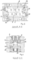
- the slide 2 u. 3 are provided in the lower region of their contact surfaces with a dovetail-shaped recess 6.
- the jaws 7 u. 8 attached on the sliders 2 u. 3, the jaws 7 u. 8 attached. These clamping jaws are interchangeable and thus adaptable to the respective workpiece. They can be fixed by means of screws 13 and 10 nuts.
- the slide 2 u. 3 are hydraulically driven, via the plunger 9 u. 10 for clamping and by means of plunger 11 u. 12 to relax.
- the plunger 9 u. 10 are in the piston plates 15; 16 arranged so that the force emanating from them directly on the end faces 17; 18, the slider 2; 3 is initiated in this.
- the line of action of the plunger 9, 10 for the slides 2, 3 lies in the guide surfaces within the recesses 4, 5. It is thus a pure longitudinal force introduced without lateral moments, thereby the friction force in the guide surfaces is significantly reduced.
- the slides run smoothly and evenly in their guide surfaces and transmit the force directly to the clamping point 19 and the workpiece 20 without deforming them.
- the result is the workpiece 20 equal oppositely directed forces according to the principle action equal reaction.
- the resulting load moment - clamping force x lever arm a - is determined by the guide surfaces within the recess 4; 5 recorded, wherein the recess 4; 5 corresponds with their guide surfaces in about the case length. These relatively large guide surfaces help to keep the friction forces as low as possible.
- a piston 22 is provided for fixing below the recess 4; This piston 22 is driven separately. It is provided at its head end with a dovetail-shaped wedge piece 23, which is fitted exactly in a recessed in the slide 2, 3 recess 6, in such a way that in the relaxed state, the slide 2; 3 slide past the wedge piece 23 without contact. The slide is guided at its contact surfaces in the recesses 6. The piston 22 is acted upon via the hydraulic connection 25. Its return takes place by means of associated plate springs 24. The provision can be made hydraulically if necessary.
- the piston 22 is acted upon by hydraulic connection 25.
- This piston is pulled down into the housing 1.
- the trained as a wedge piece 23 head is pulled down in the recess 6 and this presses on the side surfaces of the recess 6.
- the clamping element is set so that it remains independent of external forces as well as pressure drop in the hydraulic in its position and thus acts self-locking, this is effected by the configuration of the wedge piece 23.
Landscapes
- Engineering & Computer Science (AREA)
- Mechanical Engineering (AREA)
- Jigs For Machine Tools (AREA)
Claims (4)
- Élément de serrage à serrer des pièces (20), qui sont reçus déjà en leur position positionnée et dans lesquelles une reprise appuyant est requise à n'importe quels endroits, comprenant un carter (1) et des mâchoires de serrage (7, 8) qui sont aptes à être approché à ladite pièce (20) et fixé et qui sont également placées sur deux curseurs (2 ; 3) guidés en parallèle, qui sont guidés de manière glissante dans des voies de guidage,
caractérisé en cea) que lesdites voies de guidage sont encastrées dans des évidements (4 ; 5) dudit carter (1),b) que l'introduction de la force pour le mouvement desdits curseurs se fait via des pistons plongeurs (9 ; 10), qui agissent sur lesdites faces (17 ; 18) desdits curseurs en constituant ainsi un court levier entre l'introduction de la force et le point d'effet de la force,c) que lesdits pistons plongeurs (9 ; 10) sont disposés dans les plaques de piston (15 ; 16) dudit carter (1) et soumis à l'application via le même connecteur hydraulique,d) qu'un piston (22) est inséré dans ledit carter (1) au-dessous desdits curseurs (2 ; 3), qui agit en sens orthogonal par rapport au niveau desdits curseurs,e) que lesdits curseurs (2 ; 3) sont dotés d'un évidement (6) respectif, qui s'étend en coin,f) que ledit piston (22) este pourvu d'une pièce en coin (23) à sa tête, qui est guidé de façon glissante dans ledit évidement (6) desdits curseurs,g) qu'en état serré, lesdits curseurs (2 ;3) sont apte à être arrêté par leurs mâchoires de serrage (7 ; 8) portant contre ladite pièce, par application d'une pression audit piston (22), en tirant ledit piston en bas dans ledit carter (1) et ainsi tirant ladite pièce en coin (23) par sa tête dans lesdits évidements (6), en écartant lesdits curseurs et en pressant les curseurs dans les surfaces de guidage (27 ; 28) desdits évidements 4 ; 5). - Élément de serrage selon la revendication 1, caractérisé en ce que lesdits curseurs (2 ; 3) sont dotés des mâchoires de serrage (7 ; 8) échangeables et place ables.
- Élément de serrage selon la revendication 1 ou 2, caractérisé en ce que ladite pièce en coin (23) est configurée d'une telle façon, que lesdits curseurs (2 ; 3) soient arrêtés de manière autobloquante après le serrage.
- Élément de serrage selon une quelconque des revendications 1 à 3, caractérisé en ce que lesdits curseurs (2 ; 3) avec leurs mâchoires de serrage (7 ; 8) sont aptes à être approché à ladite pièce par une force agissante uniformément sur les curseurs, en laissant une force uniforme agir des deux côtes sur ladite pièce, à cette force arrêtant ladite pièce en sa position inchangée.
Applications Claiming Priority (2)
| Application Number | Priority Date | Filing Date | Title |
|---|---|---|---|
| DE10137686 | 2001-08-01 | ||
| DE10137686A DE10137686A1 (de) | 2001-08-01 | 2001-08-01 | Spannelement |
Publications (3)
| Publication Number | Publication Date |
|---|---|
| EP1281479A2 EP1281479A2 (fr) | 2003-02-05 |
| EP1281479A3 EP1281479A3 (fr) | 2009-03-18 |
| EP1281479B1 true EP1281479B1 (fr) | 2016-09-07 |
Family
ID=7693991
Family Applications (1)
| Application Number | Title | Priority Date | Filing Date |
|---|---|---|---|
| EP02102029.2A Expired - Lifetime EP1281479B1 (fr) | 2001-08-01 | 2002-07-11 | Elément de serrage avec coulisseaux à actionnement hydraulique |
Country Status (3)
| Country | Link |
|---|---|
| US (1) | US6832755B2 (fr) |
| EP (1) | EP1281479B1 (fr) |
| DE (1) | DE10137686A1 (fr) |
Families Citing this family (8)
| Publication number | Priority date | Publication date | Assignee | Title |
|---|---|---|---|---|
| DE10137686A1 (de) * | 2001-08-01 | 2003-02-13 | Rudolf Kohlert | Spannelement |
| CN102848265A (zh) * | 2012-10-09 | 2013-01-02 | 江苏润孚机械轧辊制造有限公司 | 铣床万能支架 |
| CN102975054A (zh) * | 2013-01-04 | 2013-03-20 | 江苏天宏自动化科技有限公司 | 一种锅式定位压紧机构 |
| CN107471231B (zh) * | 2017-08-02 | 2024-02-13 | 宁夏巨能机器人股份有限公司 | 一种用于夹取异形工件的机器人手爪装置 |
| DE202020000509U1 (de) | 2020-02-07 | 2020-03-12 | Christof Steubing | Spann-, Greif-, Positionier- und Haltevorrichtung |
| US11759914B2 (en) | 2020-08-06 | 2023-09-19 | Mate Precision Technologies Inc. | Vise assembly |
| WO2022032148A1 (fr) | 2020-08-06 | 2022-02-10 | Mate Precision Technologies Inc. | Ensemble base d'usinage |
| CN114714390A (zh) * | 2022-04-27 | 2022-07-08 | 斯派科智能科技(东莞)有限公司 | 气动夹爪 |
Family Cites Families (11)
| Publication number | Priority date | Publication date | Assignee | Title |
|---|---|---|---|---|
| US1736363A (en) * | 1927-11-05 | 1929-11-19 | Tabor Mfg Co | Molding-machine clamp |
| US1812959A (en) * | 1928-07-23 | 1931-07-07 | Whitehead & Kales Co | Apparatus for making wheel spiders |
| US2679177A (en) * | 1953-05-13 | 1954-05-25 | Gepfert Franklin Gahl | Precision vise of the double-acting type |
| US4257513A (en) * | 1979-04-26 | 1981-03-24 | Siarto Machine And Tool Co., Inc. | Machine tool |
| US4865375A (en) * | 1988-05-31 | 1989-09-12 | Amp Incorporated | Gripper head |
| JPH0624574Y2 (ja) * | 1988-11-09 | 1994-06-29 | 日本精工株式会社 | クランプ装置付リニアガイド装置 |
| DE19650431B4 (de) * | 1996-12-05 | 2004-04-08 | Schunk Gmbh & Co. Kg Fabrik Für Spann- Und Greifwerkzeuge | Greifvorrichtung |
| DE19902596A1 (de) * | 1999-01-23 | 2000-08-24 | Kirsching Franz | Integrierte Klemmung für Linearführungen |
| IT1314646B1 (it) * | 2000-02-11 | 2002-12-31 | Gimatic Spa | Sistema di guida delle griffe in pinze azionate da un fluido. |
| DE20100104U1 (de) * | 2001-01-04 | 2001-04-05 | Graf, Stephan, Dipl.-Ing. (FH), 79106 Freiburg | Parallelgreifer mit entkoppelten Greiferbacken |
| DE10137686A1 (de) * | 2001-08-01 | 2003-02-13 | Rudolf Kohlert | Spannelement |
-
2001
- 2001-08-01 DE DE10137686A patent/DE10137686A1/de not_active Ceased
-
2002
- 2002-07-11 EP EP02102029.2A patent/EP1281479B1/fr not_active Expired - Lifetime
- 2002-07-22 US US10/200,873 patent/US6832755B2/en not_active Expired - Lifetime
Also Published As
| Publication number | Publication date |
|---|---|
| US20030025260A1 (en) | 2003-02-06 |
| DE10137686A1 (de) | 2003-02-13 |
| EP1281479A3 (fr) | 2009-03-18 |
| US6832755B2 (en) | 2004-12-21 |
| EP1281479A2 (fr) | 2003-02-05 |
Similar Documents
| Publication | Publication Date | Title |
|---|---|---|
| EP0936366B1 (fr) | Frein pour guidage linéaire | |
| CH654779A5 (de) | Pneumatisch angetriebene spannvorrichtung. | |
| EP3569354B1 (fr) | Dispositif de fixation de pièces à usiner et installation d'usinage | |
| EP0388721B1 (fr) | Presse avec cadre d'outil insérable dans la presse | |
| DE9218907U1 (de) | Formspannbacken zum Einspannen von Werkstücken | |
| EP1281479B1 (fr) | Elément de serrage avec coulisseaux à actionnement hydraulique | |
| DE3436075C1 (de) | Vorrichtung zur Ioesbaren Verbindung von Greiferschienenteilen der Greiferschienen in einer Transfer-Presse | |
| DE1459339A1 (de) | Kniehebelpresse | |
| DE102011115326B4 (de) | Positioniereinrichtung für eine Presseinrichtung und Presseinrichtung | |
| EP1824641B1 (fr) | Element de serrage de pieces, notamment un etau | |
| DE2605085B2 (de) | Vorrichtung zur Verhütung der Beschädigung von Werkzeug und Werkstück an einer hydraulisch oder pneumatisch betätigten Stanzpresse | |
| EP2783795B1 (fr) | Mâchoire de serrage | |
| DE3221834C2 (de) | Schienenzange | |
| DD244710B1 (de) | Greiferschienenwechsel- und positioniereinrichtung fuer den automatischen werkzeugwechsel an pressen, insbesondere transferpressen | |
| DE19858837B4 (de) | Presse zum Innenhochdruckumformen | |
| DE29918229U1 (de) | Probenhalter zum Spannen von Werkstücken | |
| DE19717467A1 (de) | Spannstock | |
| DE102010038812B4 (de) | Presse zur Herstellung laminierter Bauteile größerer Länge | |
| DE10135281A1 (de) | Spannelement zum positionsflexiblen Spannen von Werkstücken | |
| DE19645627C5 (de) | Hydraulische Presse | |
| DE3020545A1 (de) | Vorrichtung zum einbringen von loechern in einem bauelement | |
| EP0612386B1 (fr) | Vanne d'arret | |
| DE3039906C2 (de) | Pneumatisch angetriebene Spannvorrichtung, insbesondere Maschinenschraubstock | |
| DE866461C (de) | Kniehebelpresse | |
| EP1044758A2 (fr) | Elément de support pour la fixation de pièces de travail |
Legal Events
| Date | Code | Title | Description |
|---|---|---|---|
| PUAI | Public reference made under article 153(3) epc to a published international application that has entered the european phase |
Free format text: ORIGINAL CODE: 0009012 |
|
| AK | Designated contracting states |
Designated state(s): AT BE BG CH CY CZ DE DK EE ES FI FR GB GR IE IT LI LU MC NL PT SE SK TR |
|
| AX | Request for extension of the european patent |
Extension state: AL LT LV MK RO SI |
|
| RAP1 | Party data changed (applicant data changed or rights of an application transferred) |
Owner name: LUDWIG EHRHARDT GMBH |
|
| PUAL | Search report despatched |
Free format text: ORIGINAL CODE: 0009013 |
|
| AK | Designated contracting states |
Kind code of ref document: A3 Designated state(s): AT BE BG CH CY CZ DE DK EE ES FI FR GB GR IE IT LI LU MC NL PT SE SK TR |
|
| AX | Request for extension of the european patent |
Extension state: AL LT LV MK RO SI |
|
| 17P | Request for examination filed |
Effective date: 20090918 |
|
| AKX | Designation fees paid |
Designated state(s): AT CH DE FR GB LI |
|
| 17Q | First examination report despatched |
Effective date: 20091221 |
|
| GRAP | Despatch of communication of intention to grant a patent |
Free format text: ORIGINAL CODE: EPIDOSNIGR1 |
|
| RIC1 | Information provided on ipc code assigned before grant |
Ipc: B25B 5/06 20060101ALI20160113BHEP Ipc: B25B 1/18 20060101AFI20160113BHEP |
|
| INTG | Intention to grant announced |
Effective date: 20160127 |
|
| GRAS | Grant fee paid |
Free format text: ORIGINAL CODE: EPIDOSNIGR3 |
|
| GRAA | (expected) grant |
Free format text: ORIGINAL CODE: 0009210 |
|
| AK | Designated contracting states |
Kind code of ref document: B1 Designated state(s): AT CH DE FR GB LI |
|
| REG | Reference to a national code |
Ref country code: GB Ref legal event code: FG4D Free format text: NOT ENGLISH |
|
| REG | Reference to a national code |
Ref country code: CH Ref legal event code: EP |
|
| REG | Reference to a national code |
Ref country code: DE Ref legal event code: R096 Ref document number: 50216176 Country of ref document: DE |
|
| REG | Reference to a national code |
Ref country code: AT Ref legal event code: REF Ref document number: 826412 Country of ref document: AT Kind code of ref document: T Effective date: 20161015 |
|
| REG | Reference to a national code |
Ref country code: CH Ref legal event code: NV Representative=s name: ROSENICH PAUL; KUENSCH JOACHIM PATENTBUERO PAU, LI |
|
| REG | Reference to a national code |
Ref country code: DE Ref legal event code: R097 Ref document number: 50216176 Country of ref document: DE |
|
| PLBE | No opposition filed within time limit |
Free format text: ORIGINAL CODE: 0009261 |
|
| STAA | Information on the status of an ep patent application or granted ep patent |
Free format text: STATUS: NO OPPOSITION FILED WITHIN TIME LIMIT |
|
| REG | Reference to a national code |
Ref country code: FR Ref legal event code: PLFP Year of fee payment: 16 |
|
| 26N | No opposition filed |
Effective date: 20170608 |
|
| REG | Reference to a national code |
Ref country code: FR Ref legal event code: PLFP Year of fee payment: 17 |
|
| PGFP | Annual fee paid to national office [announced via postgrant information from national office to epo] |
Ref country code: CH Payment date: 20190725 Year of fee payment: 18 |
|
| REG | Reference to a national code |
Ref country code: CH Ref legal event code: PCAR Free format text: NEW ADDRESS: ROTENBODENSTRASSE 12, 9497 TRIESENBERG (LI) |
|
| REG | Reference to a national code |
Ref country code: CH Ref legal event code: PL |
|
| PG25 | Lapsed in a contracting state [announced via postgrant information from national office to epo] |
Ref country code: CH Free format text: LAPSE BECAUSE OF NON-PAYMENT OF DUE FEES Effective date: 20200731 Ref country code: LI Free format text: LAPSE BECAUSE OF NON-PAYMENT OF DUE FEES Effective date: 20200731 |
|
| REG | Reference to a national code |
Ref country code: DE Ref legal event code: R082 Ref document number: 50216176 Country of ref document: DE Representative=s name: TAPPE, UDO, DIPL.-PHYS. DR.RER.NAT., DE |
|
| PGFP | Annual fee paid to national office [announced via postgrant information from national office to epo] |
Ref country code: AT Payment date: 20210720 Year of fee payment: 20 Ref country code: FR Payment date: 20210722 Year of fee payment: 20 |
|
| PGFP | Annual fee paid to national office [announced via postgrant information from national office to epo] |
Ref country code: DE Payment date: 20210731 Year of fee payment: 20 Ref country code: GB Payment date: 20210722 Year of fee payment: 20 |
|
| REG | Reference to a national code |
Ref country code: DE Ref legal event code: R071 Ref document number: 50216176 Country of ref document: DE |
|
| REG | Reference to a national code |
Ref country code: GB Ref legal event code: PE20 Expiry date: 20220710 |
|
| REG | Reference to a national code |
Ref country code: AT Ref legal event code: MK07 Ref document number: 826412 Country of ref document: AT Kind code of ref document: T Effective date: 20220711 |
|
| PG25 | Lapsed in a contracting state [announced via postgrant information from national office to epo] |
Ref country code: GB Free format text: LAPSE BECAUSE OF EXPIRATION OF PROTECTION Effective date: 20220710 |