EP1281493B1 - Vorrichtung zur automatischen Herstellung einer Öffnung oder eines Hohlraumes in der Wand eines keramischen Produkts während des Formens in eine Form - Google Patents
Vorrichtung zur automatischen Herstellung einer Öffnung oder eines Hohlraumes in der Wand eines keramischen Produkts während des Formens in eine Form Download PDFInfo
- Publication number
- EP1281493B1 EP1281493B1 EP01830519A EP01830519A EP1281493B1 EP 1281493 B1 EP1281493 B1 EP 1281493B1 EP 01830519 A EP01830519 A EP 01830519A EP 01830519 A EP01830519 A EP 01830519A EP 1281493 B1 EP1281493 B1 EP 1281493B1
- Authority
- EP
- European Patent Office
- Prior art keywords
- punch
- cover
- cavity
- casing
- moulding
- Prior art date
- Legal status (The legal status is an assumption and is not a legal conclusion. Google has not performed a legal analysis and makes no representation as to the accuracy of the status listed.)
- Expired - Lifetime
Links
Images
Classifications
-
- B—PERFORMING OPERATIONS; TRANSPORTING
- B28—WORKING CEMENT, CLAY, OR STONE
- B28B—SHAPING CLAY OR OTHER CERAMIC COMPOSITIONS; SHAPING SLAG; SHAPING MIXTURES CONTAINING CEMENTITIOUS MATERIAL, e.g. PLASTER
- B28B1/00—Producing shaped prefabricated articles from the material
- B28B1/26—Producing shaped prefabricated articles from the material by slip-casting, i.e. by casting a suspension or dispersion of the material in a liquid-absorbent or porous mould, the liquid being allowed to soak into or pass through the walls of the mould; Moulds therefor ; specially for manufacturing articles starting from a ceramic slip; Moulds therefor
- B28B1/261—Moulds therefor
-
- B—PERFORMING OPERATIONS; TRANSPORTING
- B28—WORKING CEMENT, CLAY, OR STONE
- B28B—SHAPING CLAY OR OTHER CERAMIC COMPOSITIONS; SHAPING SLAG; SHAPING MIXTURES CONTAINING CEMENTITIOUS MATERIAL, e.g. PLASTER
- B28B7/00—Moulds; Cores; Mandrels
- B28B7/16—Moulds for making shaped articles with cavities or holes open to the surface, e.g. with blind holes
Definitions
- the present invention relates to a device for automatically producing an opening or cavity in the side of a ceramic product during moulding in a mould, known, for instance, from JP-A-05 285 920.
- a technique for forming sanitaryware conventionally includes casting of the slip in chalk moulds, that is to say, moulds in which the absorbency of the chalk is used to dehydrate the ceramic slip during moulding.
- this moulding technique advantageously allows a significant reduction in cycle times and an important increase in the life of the moulds, which can be subjected to several tens of thousands of moulding cycles.
- a first problem relates to keeping the ceramic slip pressurised during item moulding.
- the fluid slip inserted in the mould by pressure casting, tends to easily fill the spaces between the mobile parts of the devices, required by the functional movements of the devices, meaning that the use of complex sealing systems which are not easily implemented is essential.
- a second problem relates to the size of these devices inside the mould. Their arrangement in the moulds is often not compatible with the circuits which carry the fluids essential to implementation of the moulding cycle through the mould and which allow correct mould operation.
- the aim of the present invention is to provide a solution to all of the problems in the prior art using a device for producing an opening or cavity in the side of a ceramic product during product moulding in a mould, the mould having a moulding cavity delimited by a moulding surface with a window, the device comprising a punch joined on the window in such a way that it projects into or, vice versa, is retracted from the moulding cavity.
- the device is characterised in that the punch is deformable with variations in its rigidity.
- the device also comprises punch shape variation differential constriction means and actuator means for punch deformation which, in the active condition, are designed to change the shape of the punch by counteracting the opposite reaction of the constriction means.
- the constriction means and actuator means produce a controlled, anisotropic deformation of the punch designed to make the punch project into the moulding cavity.
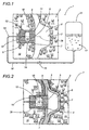
- the numeral 1 denotes as a whole a device for producing an opening 4 or cavity in the side of a ceramic product 2 during moulding in a mould 3.
- the device 1 basically comprises: a punch 5 for forming the opening 4 or cavity, designed to be suitably deformable, with a variable increase in rigidity; actuator means 33 for deforming the punch 5; and constriction means 14 and 8 for constraining the free deformation of the punch 5 - following application of the load of the actuator means 33 - counteracting it in a differential fashion, so that the deformation is suitably anisotropic and controlled.
- the punch 5 is joined to a window 11 made in a moulding surface 7 surrounding a moulding cavity 6 in the mould 3 and, thanks to the above-mentioned deformation capacity, can project into the moulding cavity 6 of the mould 3 or vice versa, it can be retracted from the moulding cavity 6, below or behind the moulding surface 7: this punch 5 projection-and retraction is suitably synchronised with the ceramic product 2 moulding process.
- the punch 5 comprises an expandable cover 12 whose shape may change, housed in a seat 14 in the body 15 of the mould 3 and having an internal cavity 13 which can hold a fluid substance 17 which makes the cover 12 deformable due to the body mobility of and/or any pressurisation applied to the fluid substance 17 in the cavity 13 from outside.
- the cover 12 may be made in the form of a membrane which expands due to a difference in the pressure acting between the fluid substance 17 contained in the cavities 13 and the outside environment.
- the membrane which forms the cover 12 may be made using an elastomeric material able to withstand significant expansion due to the difference in pressure between the cavity 13 and the outside, or it may be made of a material which is not elastic, or an elastic material which expands only slightly under the action of the pressure load.
- the cover 12 may have an entire range of intermediate elasticity values, which may be obtained not only with a suitable choice of material for the membrane, but also by integrating the membrane with a framework 36.
- the framework 36 which may be incorporated, for example, in the membrane structure during the formative process, can be made in various ways, one being the insertion of a sheet of fabric or mesh in the body of material which is the cover 12.
- the sheet of fabric or, even better the mesh are shaped in such a way as to provide local resistances which vary from one zone of the cover 12 to another, not only is it possible to regulate the degree of elasticity of the cover 12 as a whole, but it is also possible to regulate the elasticity of the cover 12 from one zone to another, allowing the cover 12 to produce a preset anisotropic deformation which is differentiated from one zone to another.
- the cover 12 may be made in various ways, representing embodiments which are provided by way of example, without limiting the scope of the invention.
- the cover 12 may have a single connection configuration, that is to say, with a single lobe.
- it has a multi-lobe configuration, with a plurality of projections 32 angled towards the moulding cavity 6 of the mould 3 and which can be connected to a matching plurality of windows 11 collectively attached to a single cavity 13, or to a plurality of individual cavities, not illustrated in the accompanying drawings.
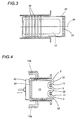
- Figure 4 also illustrates an alternative embodiment with a cover 12a with variable cross-section.
- the punch 5 may be fitted with a casing 16 covering at least part of the cover 12 itself.
- the casing 16 of suitable thickness, may be integrated in a single body with the cover 12.
- the cover 12 and casing 16 together form a preferred embodiment of the punch 5 as a whole.
- the cover 12 alone may act as the punch 5, as indicated in the description below.
- the casing 16 and/or cover 12 are preferably made of an elastomeric material.
- a silicone rubber with the following characteristics: great elasticity, great resistance to abrasion, with Poisson coefficient 0.5 and linear elastic behaviour within a wide range of loads, is preferred for the application in question.
- Figure 1 illustrates an open cavity 13, intercommunicating with the outside and designed to exchange the fluid substance 17 needed for punch 5 operation with it.
- punch 5 operation is achieved using a closed cavity 13, therefore, operating without exchanging the mass of fluid substance 17 with the outside.
- the fluid substances 17, which can be used in the punch 5 cavity 13, may be numerous and varied. It is possible to use a gaseous fluid which can be compressed, such as air, gas, steam, etc. or even a liquid which cannot be compressed, such as oil and water, or a gelatinous fluid, more or less viscous, or even loose solid substances, provided that they run smoothly, as do some finely separated solid powders.
- a gaseous fluid which can be compressed such as air, gas, steam, etc. or even a liquid which cannot be compressed, such as oil and water, or a gelatinous fluid, more or less viscous, or even loose solid substances, provided that they run smoothly, as do some finely separated solid powders.
- the punch 5 shape variation differential constriction means consist of a seat 14 in the body 15 of the mould 3, in which the punch 5 is housed.
- the seat 14 has rigid walls formed by a tubular body 39, open at one end, and a base wall 10, closing the opposite end of the tubular body 39.
- the seat 14 is located on the opposite side of one of the mould 3 moulding surfaces 7 to the side on which the moulding cavity 6 is located.
- the seat is joined to the moulding surface 7 at a window 11 made in the surface, whose shape matches the shape of the opening 4 or cavity which is to be made in the side of the ceramic product 2 being made.
- the tubular body 39 of the seat 14 has a circular cylindrical shape.
- the seat 14 may have various shapes, that is to say, it may be a circular cylinder, an elliptical cylinder, or prismatic, or even prismatic with a star-shaped base.
- cover 12 shape variation differential constriction means may consist, alternatively, but also in addition to the seat 14, of a cage or a case 8 which encompasses the punch 5 cover 12, or the casing 16, along at least part of its side surface.
- the cage or case 8 is designed to counteract the corresponding transversal expansion of the cover 12 - however it is obtained - when suitably deformed, leaving the punch 5 free to expand along its axial direction 29 so that it can exit the window 11.
- the cage or case 8 may have many shapes. One of them, illustrated in Figure 3 by way of example and without limiting the scope of the invention, includes one or more rings 30 located on the punch 5, around the casing 16, so as to circumscribe at least part of the side surface of the punch 5.
- the cage 8 may be made of an antifriction material, such as tetrafluoropolyethylene, so that it does not prevent the cover 12 shape changes along its axial direction 29; or it may consist of rings 30, with a circular cross-section, which may move independently of one another, designed to substitute sliding friction with rolling friction.
- the latter characteristic is particularly advantageous when the rings 30 interact, on one hand with the side surface of the punch 5, and on the other hand with the rigid wall 9 of the tubular body 39 of the seat 14, whose rubbing may in the long-term wear the side surface of the punch 5.
- the cover 12 shape variation differential constriction means 8 may consist, in addition to or alternatively to the embodiment just described, of the same structure as the cover 12 or casing 16 when they are designed so that they are capable of the above-mentioned anisotropic deformation.
- the projections 32 on the cover 12, with or without the casing 16 may be made in such a way that they are more deformable than the remaining part of the cover 12 inside the seat 14.
- the constriction means evidently represented by the greater inelasticity of the part of the cover 12 without the projections 32, allow the cover 12 to be deformed more longitudinally to its axial direction 29 and confine all or most of the deformation to the projections 32 themselves, which can be projected though the relative windows 11 into the forming cavity 6, or removed from the moulding cavity 6, depending on the requirements of the moment relative to the ceramic product 2 moulding cycle.
- the actuator means 33 which activate the punch 5 deformation are made in different shapes, partly linked to the nature of the fluid substance 17 used, and whether or not the cover 12 internal cavity 13 is designed to exchange the mass of fluid substance 17 with the environment outside the punch 5.
- the actuator means 33 comprise: a delivery pipe 18 communicating with the cover 12 internal cavity 13; and pressurised fluid generator means 21, connected to the delivery pipe 18.
- Cover 12 internal pressurisation changes the shape of the cover until it interacts with the rigid walls 9 and 10 of the tubular body 39, allowing the punch 5 to exit the window 11 and project into the moulding cavity 6.
- Cover 12 internal pressurisation may be obtained either using a fluid substance which cannot be compressed, as illustrated in Figure 1, or with a fluid substance which can be compressed.
- the actuator means 33 may be made in such a way as to deform the punch 5 by pressurising the fluid substance 17 inside with a deforming action applied mechanically from the outside.
- Figure 4 shows how, by crushing or squeezing the cover 12, at part of its side surface and directed from the outside inwards, it is possible to achieve a controlled pressurisation of the fluid mass 17 contained in the cavity 13, suitably deforming the remaining parts of the punch 5, and allowing the punch to project into the moulding cavity 6 and be held there rigidly enough to bear the mechanical actions of the slip during moulding of the ceramic product 2.
- the use of a gelatinous or powdery fluid substance 17 inside the cover 12 cavity 13 is preferred.
- the crushing action may be produced in a variety of ways, for example using a mechanical or hydraulic piston 40 connected to the cover 12 at the base 10 of the seat 14.
- the device 1 also comprises means for free or forced punch 5 retraction under the moulding surface 7, designed to depress the cover 12 and to draw the punch 5 back into the tubular seat 14, in the absence of pressure in the cover 12 internal cavity 13, however this may be produced.
- the retraction means may consist of the elasticity of the material used to make the punch 5.
- the spontaneous elastic contraction of the material used to make the cover 12 and/or the casing 16 integral with it, following depressurisation of the cover 12 internal cavity 13, may be sufficient to draw the punch 5 back into its seat 14 when necessary.
- the retraction means are designed for forced punch 5 retraction below the moulding surface 7, such a solution is easily obtained by connecting the device 1 to vacuum generator means (not illustrated in the accompanying drawings, being of the conventional type) which create a vacuum in the punch 5 cavity 13 sufficient to draw the punch 5 back into the seat 14, when necessary due to the functional requirements of the mould 3 operating cycle.
- device 1 operation may be briefly described by observing that suitable pressurisation of the cover 12 internal cavity 13 allows the punch 5 to be deformed in such a way as to give it suitable rigidity, making it gradually exit its seat 14 by a preset and controlled distance from the moulding surface 7 (compare Figures 1 and 2 in particular) and correlated to the thickness of the side of the product 2.
- the punch 5 With the punch 5 in these conditions, the material used to make the ceramic product 2, that is to say, the "slip" is fed into the moulding cavity 6. After a time suitable for moulding the side of the product 2 being made and allowing sufficient hardening (in accordance with know methods, which do not fall within the scope of the present invention, and therefore, are omitted), the punch 5 is drawn back into its seat 14, so that, with the moulding already complete, it allows the product 2 to be removed in any direction, that is to say, even across the direction of movement of the punch 5 in or from its seat 14.
- the punch 5 described above acts in conjunction with the wall of the seat 14 of the mould 3 which houses it in the mass of material, with circumferential interference, whose intensity may be dosed in any way by adjusting the more or less intense pressurisation of the punch 5 internal cavity 13. It is, therefore, possible to achieve a strong seal between the punch 5 casing 16 which is elastic, or at least deformable, and the rigid wall of the seat 14 which opposes the punch 5 circumferential expansion. This seal guarantees that during slip pressure moulding, the slip does not infiltrate the seat 14 housing the punch 5 between the casing 16 and the rigid countering wall 9 or 10.
- the punch 5 helps to make the above-mentioned seal even more effective.
- the intensity of this interference increases with an increase in the pressure of the slip against the punch 5. If the fluid substance 17 is of the type which cannot be compressed, and if the valve means 19 are configured in such a way as to stop fluid reflux from the chamber 13 to the generator means 21, all of this makes it practically impossible for the slip to penetrate the seat 14 housing the punch 5 and to compromise correct operation of the device 1.
- the simplicity of the construction and assembly and reduced costs of the device 1 allow easy substitution of the punch 5 when necessary after intolerable deterioration of the outer surface of the casing 16.
Landscapes
- Engineering & Computer Science (AREA)
- Chemical & Material Sciences (AREA)
- Ceramic Engineering (AREA)
- Manufacturing & Machinery (AREA)
- Mechanical Engineering (AREA)
- Dispersion Chemistry (AREA)
- Press-Shaping Or Shaping Using Conveyers (AREA)
- Devices For Post-Treatments, Processing, Supply, Discharge, And Other Processes (AREA)
Claims (55)
- Vorrichtung zur Herstellung einer Öffnung (4) oder eines Hohlraumes in der Seite eines keramischen Produktes (2) während des Formens in einer Form (3), wobei die Form (3) mit einer Formhöhlung (6) versehen ist, eingegrenzt durch eine Formfläche (7), welche ein Fenster (11) aufweist, wobei die Vorrichtung (1) einen Formdom (5) enthält, der sich mit dem Fenster (11) auf solche Weise zusammenfügt, dass er in die Formhöhlung (6) hineinragt oder sich aus dieser zurückzieht, und wobei die Vorrichtung dadurch gekennzeichnet ist, dass der Formdorn (5) mit Veränderungen in seiner Steifheit ausdehnbar ist; wobei die Vorrichtung (1) differenzierte Verengungsmittel (14; 8) zur Formveränderung enthält; sowie Triebmittel (33) zur Verformung des Formdorns (5), welche in ihrem aktiven Zustand dazu bestimmt sind, die Form des Formdorns (5) entgegen der Gegenwirkung durch die Verengungsmittel (14; 8) zu verändern; und wobei die Verengungsmittel (14; 8) und die Triebmittel (33) eine gesteuerte anisotropische Verformung des Formdorns (5) bewirken, so dass der Formdorn in die Formhöhlung (6) hineinragt.
- Vorrichtung nach Patentanspruch 1, dadurch gekennzeichnet, dass der Formdorn (5) eine Hülle (12) mit einem inneren Hohlraum (13) enthält, dazu bestimmt, eine fliessende Substanz (17) zu aufzunehmen, wobei die Hülle durch die Wirkung der fliessenden Substanz, welche sie enthält, (17) verformbar ist; wobei die Triebmittel (33) eine Veränderung der Form der Hülle (12) entgegen der Gegenwirkung der Verengungsmittel (14; 8) bewirken, dazu bestimmt, den Formdorn (5) in die Formhöhlung (6) eintreten zu lassen.
- Vorrichtung nach Patentanspruch 2, dadurch gekennzeichnet, dass der innere Hohlraum (13) verschlossen ist, um einen Austausch der fliessenden Substanz (17) mit dem Umfeld ausserhalb des Hohlraumes (13) zu vermeiden.
- Vorrichtung nach Patentanspruch 2, dadurch gekennzeichnet, dass der Hohlraum (13) offen ist, um einen Austausch der fliessenden Substanz (17) mit dem Umfeld ausserhalb des Hohlraumes (13) zu erlauben.
- Vorrichtung nach einem beliebigen der Patentansprüche von 2 bis 4, dadurch gekennzeichnet, dass die fliessende Substanz (17) gasförmig ist.
- Vorrichtung nach einem beliebigen der Patentansprüche von 2 bis 4, dadurch gekennzeichnet, dass die fliessende Substanz (17) flüssig ist.
- Vorrichtung nach einem beliebigen der Patentansprüche von 2 bis 4, dadurch gekennzeichnet, dass die fliessende Substanz (17) eine lose, unzusammenhängende Substanz ist.
- Vorrichtung nach Patentanspruch 7, dadurch gekennzeichnet, dass die lose, unzusammenhängende Substanz ein fein geteiltes Pulver ist.
- Vorrichtung nach einem beliebigen der Patentansprüche von 2 bis 4, dadurch gekennzeichnet, dass die fliessende Substanz (17) eine gallertartige Substanz ist.
- Vorrichtung nach Patentanspruch 2, dadurch gekennzeichnet, dass die Hülle (12) ausdehnbar ist aufgrund einer Druckdifferenz, die zwischen der inneren fliessenden Substanz (17) und dem Umfeld ausserhalb des Hohlrau-mes (13) wirkt.
- Vorrichtung nach Patentanspruch 10, dadurch gekennzeichnet, dass die Hülle (12) aus einem elastischen Material hergestellt ist.
- Vorrichtung nach Patentanspruch 10, dadurch gekennzeichnet, dass die Hülle (12) aus einem Material mit einer Verformbarkeit hergestellt ist, die sich je nach der Verformungsrichtung verändert, wobei die differenzierten Verengungsmittel aus dem gleichen Material wie das der Hülle (12) hergestellt sind.
- Vorrichtung nach Patentanspruch 12, dadurch gekennzeichnet, dass die Hülle (12) eine Armierung (36) enthält, dazu bestimmt, der Hülle (12) eine bestimmte anisotropische Verformungskapazität zu verleihen.
- Vorrichtung nach einem beliebigen der vorstehenden Patentansprüche, dadurch gekennzeichnet, dass die Hülle (12) eine Anzahl von Vorsprüngen (32) aufiveist, die mit einer passenden Anzahl von Fenstern (11) zusammengefiigt werden können.
- Vorrichtung nach Patentanspruch 14, dadurch gekennzeichnet, dass ein einziger Hohlraum (13) auf solche Weise durch den Vorsprüngen (32) zugeordnet ist, dass diese die Formdorne (5) in die Formhöhlung (6) hineinschieben oder sie aus der Formhöhlung (6) zurückziehen.
- Vorrichtung nach Patentanspruch 14, dadurch gekennzeichnet, dass sie eine Anzahl von Hohlräumen (13) enthält, zugeordnet den Vorsprüngen (32), so dass diese die Formdorne (5) in die Formhöhlung (6) hineinschieben oder sie aus der Formhöhlung (6) zurückziehen.
- Vorrichtung nach Patentanspruch 1 oder 16, dadurch gekennzeichnet, dass der Formdom (5) einen Mantel (16) von geeigneter Stärke enthält, um die Hülle (12) wenigstens teilweise abzudecken.
- Vorrichtung nach Patentanspruch 17, dadurch gekennzeichnet, dass der Mantel (16) wenigstens teilweise aus einem Elastomermaterial hergestellt ist.
- Vorrichtung nach Patentanspruch 18, dadurch gekennzeichnet, dass das Elastomermaterial ein Silikongummi ist.
- Vorrichtung nach Patentanspruch 17, dadurch gekennzeichnet, dass der Mantel (16) aus Metall ist.
- Vorrichtung nach einem beliebigen der vorstehenden Patentansprüche von 17 bis 20, dadurch gekennzeichnet, dass der Mantel (16) wenigstens einen Einsatz (31) aus einem geeigneten Material enthält.
- Vorrichtung nach einem beliebigen der vorstehenden Patentansprüche von 17 bis 20, dadurch gekennzeichnet, dass der Mantel (16) durch eine Kappe (34) abgedeckt ist, hergestellt aus einem geeigneten Material.
- Vorrichtung nach einem beliebigen der vorstehenden Patentansprüche von 17 bis 20, dadurch gekennzeichnet, dass der Mantel (16) und die Hülle (12) integriert sind und einen einzigen Körper bilden.
- Vorrichtung nach Patentanspruch 1, dadurch gekennzeichnet, dass der Formdorn (5) mit einem Mantel (16) von geeigneter Stärke versehen ist.
- Vorrichtung nach Patentanspruch 24, dadurch gekennzeichnet, dass der Mantel (16) aus einem Elastomermaterial hergestellt ist.
- Vorrichtung nach Patentanspruch 25, dadurch gekennzeichnet, dass das Elastomermaterial ein Silikongummi ist.
- Vorrichtung nach Patentanspruch 24, dadurch gekennzeichnet, dass der Mantel (16) wenigstens teilweise aus Metall hergestellt ist.
- Vorrichtung nach einem beliebigen der Patentansprüche von 24 bis 27, dadurch gekennzeichnet, dass der Mantel (16) wenigstens einen Einsatz (31) enthält, der aus einem geeigneten Material hergestellt ist.
- Vorrichtung nach Patentanspruch 28, dadurch gekennzeichnet, dass der Einsatz (31) aus einem gegen Abrieb widerstandsfähigen Material hergestellt ist.
- Vorrichtung nach einem beliebigen der Patentansprüche von 24 bis 28, dadurch gekennzeichnet, dass der Mantel (16) durch eine Kappe (34) aus einem geeigneten Material abgedeckt ist.
- Vorrichtung nach einem beliebigen der Patentansprüche von 24 bis 30, dadurch gekennzeichnet, dass der Mantel (16) des Formdorns (5) aus einem Material hergestellt ist, das eine Verformbarkeit aufweist, die sich je nach Richtung der Verformung verändert, wobei die differenzierten Verengungsmittel (8) aus demselben Material hergestellt sind wie der Mantel (16).
- Vorrichtung nach Patentanspruch 31, dadurch gekennzeichnet, dass der Mantel (16) des Formdorns (5) eine Armierung (36) enthält, dazu bestimmt, dem Mantel (16) eine anisotropische Verformungskapazität zu verleihen.
- Vorrichtung nach einem beliebigen der Patentansprüche von 24 bis 32, dadurch gekennzeichnet, dass der Mantel (16) eine Anzahl von Vorsprüngen (32) aufweist, die mit einer Anzahl von Fenstern (11) zusammengerügt werden können.
- Vorrichtung nach Patentanspruch 1, dadurch gekennzeichnet, dass die differenzierten Verengungsmittel zur Formveränderung des Formdorns (5) aus einem Sitz (14) in dem Körper (15) der Form (3) bestehen, eingegrenzt durch starre, umlaufende Wände (9, 10), die an dem Fenster (11) befestigt sind und den Formdorn (5) aufnehmen, wobei die starren Wände (9, 10) der Verformung des Formdorns (5) entgegenwirken und bewirken, dass der Formdorn (5) zum einem Teil aus dem Fenster (11) austritt und sich in die Formhöhlung (6) der Form (3) bewegt, und zwar in eine Position, die der Öffnung (4) oder der Vertiefung in dem herzustellen keramischen Produkt (2) entspricht.
- Vorrichtung nach Patentanspruch 34, dadurch gekennzeichnet, dass der Sitz (14) eine rohrförmige Auslegung und eine abschliessende Bodenwand (10) hat, angeordnet dem Fenster (11) gegenüberliegend.
- Vorrichtung nach Patentanspruch 35, dadurch gekennzeichnet, dass der Sitz (14) in seiner Form zylindrisch ist.
- Vorrichtung nach Patentanspruch 36, dadurch gekennzeichnet, dass die zylindrische Form des Sitzes (14) einen elliptischen Querschnitt hat.
- Vorrichtung nach Patentanspruch 35, dadurch gekennzeichnet, dass der Sitz (14) in seiner Form prismatisch ist.
- Vorrichtung nach Patentanspruch 35, dadurch gekennzeichnet, dass der Sitz (14) prismatisch mit einer sternförmigen Basis ist.
- Vorrichtung nach Patentanspruch 1, dadurch gekennzeichnet, dass die differenzierten Verengungsmittel zur Formveränderung des Formdorns (5) einen Käfig oder ein Gehäuse (8) enthalten, den Formdorn (5) wenigstens entlang einem Teil seiner seitlichen Oberfläche umgebend und dessen Verformung entgegenwirkend, wobei der Formdorn (5) frei ist, sich entlang einer axialen Richtung (29) des Formdorns (5) selbst auszudehnen.
- Vorrichtung nach Patentanspruch 40, dadurch gekennzeichnet, dass der Käfig oder das Gehäuse (8) wenigstens einen Ring (30) enthält, dazu bestimmt, die Hülle (12) zu umgeben.
- Vorrichtung nach Patentanspruch 41, dadurch gekennzeichnet, dass jeder der Ringe (30) einen kreisförmigen Querschnitt hat.
- Vorrichtung nach Patentanspruch 40 oder 41, dadurch gekennzeichnet, dass der Käfig oder das Gehäuse (8) aus einem reibungsmindernden Material hergestellt ist.
- Vorrichtung nach Patentanspruch 43, dadurch gekennzeichnet, dass das reibungsmindernde Material ein Tetrafluorpolyäthylen enthaltendes Material ist.
- Vorrichtung nach einem beliebigen der Patentansprüche von 34 bis 44, dadurch gekennzeichnet, dass der Käfig oder das Gehäuse (8) in dem Sitz (14) angeordnet ist.
- Vorrichtung nach einem beliebigen der Patentansprüche von 34 bis 45, dadurch gekennzeichnet, dass der Sitz (14) einen veränderbaren Querschnitt hat, wobei eine Hülle (12a) mit entsprechend veränderbarem Querschnitt in dem Sitz (14) aufgenommen ist.
- Vorrichtung nach Patentanspruch 1, dadurch gekennzeichnet, dass die Triebmittel (33) dazu bestimmt sind, einen örtlichen Kontaktdruck auf einen Teil der äusseren Oberfläche des Formdorns (5) auszuüben, wobei der Druck dazu dient, eine entsprechende Verformung eines anderen Teils des Formdorns (5) zu bewirken, sowie das Einschieben in oder das Zurückziehen aus der Formhöhlung (6).
- Vorrichtung nach Patentanspruch 47, dadurch gekennzeichnet, dass die Triebmittel (33) mit einer fliessenden Substanz (17) arbeiten, welche nicht komprimiert werden kann.
- Vorrichtung nach Patentanspruch 47, dadurch gekennzeichnet, dass die Triebmittel (33) mit einer fliessenden Substanz (17) arbeiten, welche komprimiert werden kann.
- Vorrichtung nach einem beliebigen der Patentansprüche von 2 bis 23, dadurch gekennzeichnet, dass die Triebmittel (33) eine Zuführleitung (18) haben, welche mit dem inneren Hohlraum (13) der Hülle (12) in Verbindung steht; sowie Erzeugermittel (21) der unter Druck stehenden fliessenden Substanz, die an die Zuführleitung (18) angeschlossen sind.
- Vorrichtung nach Patentanspruch 50, dadurch gekennzeichnet, dass die Triebmittel (33) Ventilmittel (19) für die Zuführleitung (18) enthalten, die unter zwei entgegengesetzten Bedingungen arbeiten, von welchen sie in einer jeden Rückfluss nach aussen der in dem Hohlraum der Hülle (12) enthaltenen fliessenden Substanz (17) verhindern.
- Vorrichtung nach Patentanspruch 2, dadurch gekennzeichnet, dass sie Mittel zum freien Zurückziehen des Formdorns (5) bis hinter die Formfläche (7) enthalten, die dazu bestimmt sind, den Druck der Hülle (12) zu senken und den Formdorn (5) aus der Formhöhlung (6) herauszuziehen, wenn der innere Hohlraum (13) der Hülle (12) nicht unter Druck steht.
- Vorrichtung nach Patentanspruch 52, dadurch gekennzeichnet, dass die Hülle (12) aus einem elastischen Material hergestellt ist, wobei die Mittel zum freien Zurückziehen aus dem spontanen elastischen Zusammenziehen des Materials bestehen, das zum Herstellen der Hülle (12) verwendet wurde, und zwar infolge des Druckabfalls in ihrem inneren Hohlraum (13).
- Vorrichtung nach Patentanspruch 2, dadurch gekennzeichnet, dass sie Mittel zum forcierten Zurückziehen des Formdorns (5) bis unter die Formfläche (7) enthält, wobei diese dazu bestimmt sind, von aussen her auf den Formdorn (5) ein Vakuum anzuwenden, das geeignet ist, den Formdom (5) zurück in seinen Sitz (14) zu ziehen.
- Vorrichtung nach Patentanspruch 54, dadurch gekennzeichnet, dass die Mittel zum forcierten Zurückziehen Mittel zum Erzeugen eines Vakuums im Inneren des Hohlraumes der Hülle (12) enthalten.
Priority Applications (7)
| Application Number | Priority Date | Filing Date | Title |
|---|---|---|---|
| AT01830519T ATE250490T1 (de) | 2001-08-03 | 2001-08-03 | Vorrichtung zur automatischen herstellung einer öffnung oder eines hohlraumes in der wand eines keramischen produkts während des formens in eine form |
| DE60100861T DE60100861T2 (de) | 2001-08-03 | 2001-08-03 | Vorrichtung zur automatischen Herstellung einer Öffnung oder eines Hohlraumes in der Wand eines keramischen Produkts während des Formens in eine Form |
| ES01830519T ES2207598T3 (es) | 2001-08-03 | 2001-08-03 | Dispositivo para la produccion automatica de una abertura o cavidad en la parte lateral de un producto ceramico durante el moldeo en el molde. |
| EP01830519A EP1281493B1 (de) | 2001-08-03 | 2001-08-03 | Vorrichtung zur automatischen Herstellung einer Öffnung oder eines Hohlraumes in der Wand eines keramischen Produkts während des Formens in eine Form |
| US09/986,599 US6761555B2 (en) | 2001-08-03 | 2001-11-09 | Device for automatically producing an opening or cavity in the side of a ceramic product during molding in a mould |
| BRPI0202962-6A BR0202962B1 (pt) | 2001-08-03 | 2002-07-29 | dispositivo para produzir automaticamente uma abertura ou cavidade na lateral de um produto cerámico durante moldagem em um molde. |
| MXPA02007561A MXPA02007561A (es) | 2001-08-03 | 2002-08-02 | Dispositivo para obtener de manera automatica en un producto ceramico, durante el moldeo en un molde, una abertura, o un fondo bajo, de pared. |
Applications Claiming Priority (1)
| Application Number | Priority Date | Filing Date | Title |
|---|---|---|---|
| EP01830519A EP1281493B1 (de) | 2001-08-03 | 2001-08-03 | Vorrichtung zur automatischen Herstellung einer Öffnung oder eines Hohlraumes in der Wand eines keramischen Produkts während des Formens in eine Form |
Publications (2)
| Publication Number | Publication Date |
|---|---|
| EP1281493A1 EP1281493A1 (de) | 2003-02-05 |
| EP1281493B1 true EP1281493B1 (de) | 2003-09-24 |
Family
ID=8184645
Family Applications (1)
| Application Number | Title | Priority Date | Filing Date |
|---|---|---|---|
| EP01830519A Expired - Lifetime EP1281493B1 (de) | 2001-08-03 | 2001-08-03 | Vorrichtung zur automatischen Herstellung einer Öffnung oder eines Hohlraumes in der Wand eines keramischen Produkts während des Formens in eine Form |
Country Status (7)
| Country | Link |
|---|---|
| US (1) | US6761555B2 (de) |
| EP (1) | EP1281493B1 (de) |
| AT (1) | ATE250490T1 (de) |
| BR (1) | BR0202962B1 (de) |
| DE (1) | DE60100861T2 (de) |
| ES (1) | ES2207598T3 (de) |
| MX (1) | MXPA02007561A (de) |
Families Citing this family (3)
| Publication number | Priority date | Publication date | Assignee | Title |
|---|---|---|---|---|
| EP2684659B1 (de) * | 2012-07-13 | 2015-05-06 | Christoph Gruss | Hinterschneidungswerkzeug und Verfahren zur Erzeugung eines Sacklochs |
| DE202012010890U1 (de) | 2012-07-13 | 2012-12-12 | Christoph Gruß | Hinterschneidungswerkzeug zur Erzeugung eines Sacklochs |
| EP2960027B1 (de) | 2014-06-25 | 2017-04-19 | Christoph Gruss | Hinterschneidungswerkzeug zur Erzeugung eines Sacklochs |
Family Cites Families (5)
| Publication number | Priority date | Publication date | Assignee | Title |
|---|---|---|---|---|
| GB2027634A (en) * | 1978-08-09 | 1980-02-27 | Ideal Standard | Casting ceramic material |
| US5087193A (en) * | 1990-08-09 | 1992-02-11 | Herbert Jr Kenneth H | Apparatus for forming a composite article |
| JPH05285919A (ja) * | 1992-04-08 | 1993-11-02 | Inax Corp | 開口付成形体の泥漿鋳込み成形法 |
| JPH05285920A (ja) * | 1992-04-10 | 1993-11-02 | Inax Corp | 開口付成形体の泥漿鋳込み成形法 |
| US5578158A (en) * | 1994-03-01 | 1996-11-26 | Massachusetts Institute Of Technology | Method and system for forming a composite product from a thermoformable material |
-
2001
- 2001-08-03 DE DE60100861T patent/DE60100861T2/de not_active Expired - Lifetime
- 2001-08-03 ES ES01830519T patent/ES2207598T3/es not_active Expired - Lifetime
- 2001-08-03 EP EP01830519A patent/EP1281493B1/de not_active Expired - Lifetime
- 2001-08-03 AT AT01830519T patent/ATE250490T1/de not_active IP Right Cessation
- 2001-11-09 US US09/986,599 patent/US6761555B2/en not_active Expired - Lifetime
-
2002
- 2002-07-29 BR BRPI0202962-6A patent/BR0202962B1/pt not_active IP Right Cessation
- 2002-08-02 MX MXPA02007561A patent/MXPA02007561A/es active IP Right Grant
Also Published As
| Publication number | Publication date |
|---|---|
| EP1281493A1 (de) | 2003-02-05 |
| ATE250490T1 (de) | 2003-10-15 |
| DE60100861D1 (de) | 2003-10-30 |
| MXPA02007561A (es) | 2005-02-17 |
| US20030026867A1 (en) | 2003-02-06 |
| BR0202962A (pt) | 2003-05-06 |
| DE60100861T2 (de) | 2004-07-15 |
| US6761555B2 (en) | 2004-07-13 |
| ES2207598T3 (es) | 2004-06-01 |
| BR0202962B1 (pt) | 2010-11-03 |
Similar Documents
| Publication | Publication Date | Title |
|---|---|---|
| US4133626A (en) | Press for pressing potlike articles from ceramic powder | |
| CN101758637B (zh) | 成型设备的反作用装置 | |
| US6761555B2 (en) | Device for automatically producing an opening or cavity in the side of a ceramic product during molding in a mould | |
| US3897531A (en) | Manufacture of compressed-powder bodies | |
| HU210373B (en) | Ring-shaped sealing arrangement and valve assembled by same | |
| US5662944A (en) | Sealing assembly for molds used for casting sanitary fixtures | |
| JP5490813B2 (ja) | 逆圧対応仕切弁 | |
| EP0047613B1 (de) | Vorrichtung zum Erzeugen hin- und hergehender Bewegungen | |
| KR880012331A (ko) | 건식고무 프레스 성형방법 및 성형장치 | |
| JP2020185600A (ja) | 鋳造装置 | |
| US20220048220A1 (en) | Sealing device for use in molded foam pad production | |
| CN107791435A (zh) | 用于填充模型的装置 | |
| CN115596736B (zh) | 一种高稳定性自锁油缸 | |
| MX2012012892A (es) | Mascara para selllar una estructura con forma de panal, y metodo de sellado para la estructura con forma de panal utilizando la misma. | |
| CN107530920A (zh) | 控制在模制操作期间由于聚合物收缩引起的缺陷的形成 | |
| SK287141B6 (sk) | Odvzdušňovací ventil na použitie do odvzdušňovacích otvorov vulkanizačných foriem | |
| CN103968071A (zh) | 密封机构 | |
| EP3028835B1 (de) | Vorrichtung zur herstellung von warmgeformten behältern | |
| US4137026A (en) | Brickmaking press | |
| SE0102191D0 (sv) | Press | |
| CN103967864B (zh) | 高压双作用自补偿薄壁液压缸 | |
| CN112753745A (zh) | 用于肉制品成型的模具滚筒 | |
| RU198624U1 (ru) | Механизм блокировки штока цилиндра | |
| ITVR970006A1 (it) | Unita' di tenuta anulare e procedimento per la sua fabbricazione | |
| JP4621632B2 (ja) | 成形体製造装置 |
Legal Events
| Date | Code | Title | Description |
|---|---|---|---|
| PUAI | Public reference made under article 153(3) epc to a published international application that has entered the european phase |
Free format text: ORIGINAL CODE: 0009012 |
|
| 17P | Request for examination filed |
Effective date: 20020701 |
|
| AK | Designated contracting states |
Designated state(s): AT BE CH CY DE DK ES FI FR GB GR IE IT LI LU MC NL PT SE TR |
|
| AX | Request for extension of the european patent |
Extension state: AL LT LV MK RO SI |
|
| GRAH | Despatch of communication of intention to grant a patent |
Free format text: ORIGINAL CODE: EPIDOS IGRA |
|
| GRAS | Grant fee paid |
Free format text: ORIGINAL CODE: EPIDOSNIGR3 |
|
| GRAA | (expected) grant |
Free format text: ORIGINAL CODE: 0009210 |
|
| AK | Designated contracting states |
Kind code of ref document: B1 Designated state(s): AT BE CH CY DE DK ES FI FR GB GR IE IT LI LU MC NL PT SE TR |
|
| PG25 | Lapsed in a contracting state [announced via postgrant information from national office to epo] |
Ref country code: CH Free format text: LAPSE BECAUSE OF FAILURE TO SUBMIT A TRANSLATION OF THE DESCRIPTION OR TO PAY THE FEE WITHIN THE PRESCRIBED TIME-LIMIT Effective date: 20030924 Ref country code: CY Free format text: LAPSE BECAUSE OF FAILURE TO SUBMIT A TRANSLATION OF THE DESCRIPTION OR TO PAY THE FEE WITHIN THE PRESCRIBED TIME-LIMIT Effective date: 20030924 Ref country code: LI Free format text: LAPSE BECAUSE OF FAILURE TO SUBMIT A TRANSLATION OF THE DESCRIPTION OR TO PAY THE FEE WITHIN THE PRESCRIBED TIME-LIMIT Effective date: 20030924 Ref country code: TR Free format text: LAPSE BECAUSE OF FAILURE TO SUBMIT A TRANSLATION OF THE DESCRIPTION OR TO PAY THE FEE WITHIN THE PRESCRIBED TIME-LIMIT Effective date: 20030924 Ref country code: AT Free format text: LAPSE BECAUSE OF FAILURE TO SUBMIT A TRANSLATION OF THE DESCRIPTION OR TO PAY THE FEE WITHIN THE PRESCRIBED TIME-LIMIT Effective date: 20030924 Ref country code: FI Free format text: LAPSE BECAUSE OF FAILURE TO SUBMIT A TRANSLATION OF THE DESCRIPTION OR TO PAY THE FEE WITHIN THE PRESCRIBED TIME-LIMIT Effective date: 20030924 Ref country code: NL Free format text: LAPSE BECAUSE OF FAILURE TO SUBMIT A TRANSLATION OF THE DESCRIPTION OR TO PAY THE FEE WITHIN THE PRESCRIBED TIME-LIMIT Effective date: 20030924 Ref country code: BE Free format text: LAPSE BECAUSE OF FAILURE TO SUBMIT A TRANSLATION OF THE DESCRIPTION OR TO PAY THE FEE WITHIN THE PRESCRIBED TIME-LIMIT Effective date: 20030924 |
|
| REG | Reference to a national code |
Ref country code: GB Ref legal event code: FG4D |
|
| REG | Reference to a national code |
Ref country code: CH Ref legal event code: EP |
|
| AKX | Designation fees paid |
Designated state(s): AT BE CH CY DE DK ES FI FR GB GR IE IT LI LU MC NL PT SE TR |
|
| REG | Reference to a national code |
Ref country code: IE Ref legal event code: FG4D |
|
| REF | Corresponds to: |
Ref document number: 60100861 Country of ref document: DE Date of ref document: 20031030 Kind code of ref document: P |
|
| PG25 | Lapsed in a contracting state [announced via postgrant information from national office to epo] |
Ref country code: GR Free format text: LAPSE BECAUSE OF FAILURE TO SUBMIT A TRANSLATION OF THE DESCRIPTION OR TO PAY THE FEE WITHIN THE PRESCRIBED TIME-LIMIT Effective date: 20031224 Ref country code: DK Free format text: LAPSE BECAUSE OF FAILURE TO SUBMIT A TRANSLATION OF THE DESCRIPTION OR TO PAY THE FEE WITHIN THE PRESCRIBED TIME-LIMIT Effective date: 20031224 Ref country code: SE Free format text: LAPSE BECAUSE OF FAILURE TO SUBMIT A TRANSLATION OF THE DESCRIPTION OR TO PAY THE FEE WITHIN THE PRESCRIBED TIME-LIMIT Effective date: 20031224 |
|
| NLV1 | Nl: lapsed or annulled due to failure to fulfill the requirements of art. 29p and 29m of the patents act | ||
| REG | Reference to a national code |
Ref country code: CH Ref legal event code: PL |
|
| REG | Reference to a national code |
Ref country code: ES Ref legal event code: FG2A Ref document number: 2207598 Country of ref document: ES Kind code of ref document: T3 |
|
| ET | Fr: translation filed | ||
| PLBE | No opposition filed within time limit |
Free format text: ORIGINAL CODE: 0009261 |
|
| STAA | Information on the status of an ep patent application or granted ep patent |
Free format text: STATUS: NO OPPOSITION FILED WITHIN TIME LIMIT |
|
| PG25 | Lapsed in a contracting state [announced via postgrant information from national office to epo] |
Ref country code: IE Free format text: LAPSE BECAUSE OF NON-PAYMENT OF DUE FEES Effective date: 20040803 Ref country code: LU Free format text: LAPSE BECAUSE OF NON-PAYMENT OF DUE FEES Effective date: 20040803 |
|
| PG25 | Lapsed in a contracting state [announced via postgrant information from national office to epo] |
Ref country code: MC Free format text: LAPSE BECAUSE OF NON-PAYMENT OF DUE FEES Effective date: 20040831 |
|
| 26N | No opposition filed |
Effective date: 20040625 |
|
| REG | Reference to a national code |
Ref country code: IE Ref legal event code: MM4A |
|
| PG25 | Lapsed in a contracting state [announced via postgrant information from national office to epo] |
Ref country code: PT Free format text: LAPSE BECAUSE OF NON-PAYMENT OF DUE FEES Effective date: 20040224 |
|
| PGFP | Annual fee paid to national office [announced via postgrant information from national office to epo] |
Ref country code: FR Payment date: 20140822 Year of fee payment: 14 |
|
| REG | Reference to a national code |
Ref country code: FR Ref legal event code: ST Effective date: 20160429 |
|
| PG25 | Lapsed in a contracting state [announced via postgrant information from national office to epo] |
Ref country code: FR Free format text: LAPSE BECAUSE OF NON-PAYMENT OF DUE FEES Effective date: 20150831 |
|
| PGFP | Annual fee paid to national office [announced via postgrant information from national office to epo] |
Ref country code: ES Payment date: 20200901 Year of fee payment: 20 Ref country code: DE Payment date: 20200721 Year of fee payment: 20 Ref country code: GB Payment date: 20200722 Year of fee payment: 20 |
|
| PGFP | Annual fee paid to national office [announced via postgrant information from national office to epo] |
Ref country code: IT Payment date: 20200721 Year of fee payment: 20 |
|
| REG | Reference to a national code |
Ref country code: DE Ref legal event code: R071 Ref document number: 60100861 Country of ref document: DE |
|
| REG | Reference to a national code |
Ref country code: GB Ref legal event code: PE20 Expiry date: 20210802 |
|
| PG25 | Lapsed in a contracting state [announced via postgrant information from national office to epo] |
Ref country code: GB Free format text: LAPSE BECAUSE OF EXPIRATION OF PROTECTION Effective date: 20210802 |
|
| REG | Reference to a national code |
Ref country code: ES Ref legal event code: FD2A Effective date: 20211203 |
|
| PG25 | Lapsed in a contracting state [announced via postgrant information from national office to epo] |
Ref country code: ES Free format text: LAPSE BECAUSE OF EXPIRATION OF PROTECTION Effective date: 20210804 |