EP1281495A1 - Procédé pour décorer des carreaux et similaires, et dispositif pour la mise en oeuvre de ce procédé - Google Patents
Procédé pour décorer des carreaux et similaires, et dispositif pour la mise en oeuvre de ce procédé Download PDFInfo
- Publication number
- EP1281495A1 EP1281495A1 EP01118419A EP01118419A EP1281495A1 EP 1281495 A1 EP1281495 A1 EP 1281495A1 EP 01118419 A EP01118419 A EP 01118419A EP 01118419 A EP01118419 A EP 01118419A EP 1281495 A1 EP1281495 A1 EP 1281495A1
- Authority
- EP
- European Patent Office
- Prior art keywords
- glaze
- decorating
- glaze film
- tiles
- film
- Prior art date
- Legal status (The legal status is an assumption and is not a legal conclusion. Google has not performed a legal analysis and makes no representation as to the accuracy of the status listed.)
- Withdrawn
Links
- 238000000034 method Methods 0.000 title claims abstract description 36
- 230000008093 supporting effect Effects 0.000 claims description 34
- 238000003892 spreading Methods 0.000 claims description 16
- 238000011144 upstream manufacturing Methods 0.000 claims description 8
- 238000013459 approach Methods 0.000 claims description 2
- 238000005034 decoration Methods 0.000 abstract description 9
- 239000010408 film Substances 0.000 description 95
- 238000005507 spraying Methods 0.000 description 10
- 239000004575 stone Substances 0.000 description 10
- 230000000694 effects Effects 0.000 description 8
- 239000000919 ceramic Substances 0.000 description 6
- 239000000203 mixture Substances 0.000 description 5
- 230000000007 visual effect Effects 0.000 description 4
- 238000004064 recycling Methods 0.000 description 3
- 150000001875 compounds Chemical class 0.000 description 2
- 239000007788 liquid Substances 0.000 description 2
- 238000004519 manufacturing process Methods 0.000 description 2
- 239000000126 substance Substances 0.000 description 2
- 241000173697 Euchloe naina Species 0.000 description 1
- 239000003086 colorant Substances 0.000 description 1
- 230000008602 contraction Effects 0.000 description 1
- 230000007547 defect Effects 0.000 description 1
- 230000001419 dependent effect Effects 0.000 description 1
- 238000009826 distribution Methods 0.000 description 1
- 230000003993 interaction Effects 0.000 description 1
- 239000004579 marble Substances 0.000 description 1
- 238000012986 modification Methods 0.000 description 1
- 230000004048 modification Effects 0.000 description 1
- 230000000704 physical effect Effects 0.000 description 1
- 230000001681 protective effect Effects 0.000 description 1
- 238000005086 pumping Methods 0.000 description 1
- 238000011160 research Methods 0.000 description 1
- 150000003839 salts Chemical class 0.000 description 1
- 239000007921 spray Substances 0.000 description 1
- 230000001360 synchronised effect Effects 0.000 description 1
- 239000010409 thin film Substances 0.000 description 1
- 238000013519 translation Methods 0.000 description 1
Images


Classifications
-
- C—CHEMISTRY; METALLURGY
- C04—CEMENTS; CONCRETE; ARTIFICIAL STONE; CERAMICS; REFRACTORIES
- C04B—LIME, MAGNESIA; SLAG; CEMENTS; COMPOSITIONS THEREOF, e.g. MORTARS, CONCRETE OR LIKE BUILDING MATERIALS; ARTIFICIAL STONE; CERAMICS; REFRACTORIES; TREATMENT OF NATURAL STONE
- C04B41/00—After-treatment of mortars, concrete, artificial stone or ceramics; Treatment of natural stone
- C04B41/009—After-treatment of mortars, concrete, artificial stone or ceramics; Treatment of natural stone characterised by the material treated
-
- B—PERFORMING OPERATIONS; TRANSPORTING
- B28—WORKING CEMENT, CLAY, OR STONE
- B28B—SHAPING CLAY OR OTHER CERAMIC COMPOSITIONS; SHAPING SLAG; SHAPING MIXTURES CONTAINING CEMENTITIOUS MATERIAL, e.g. PLASTER
- B28B11/00—Apparatus or processes for treating or working the shaped or preshaped articles
- B28B11/001—Applying decorations on shaped articles, e.g. by painting
-
- B—PERFORMING OPERATIONS; TRANSPORTING
- B28—WORKING CEMENT, CLAY, OR STONE
- B28B—SHAPING CLAY OR OTHER CERAMIC COMPOSITIONS; SHAPING SLAG; SHAPING MIXTURES CONTAINING CEMENTITIOUS MATERIAL, e.g. PLASTER
- B28B11/00—Apparatus or processes for treating or working the shaped or preshaped articles
- B28B11/04—Apparatus or processes for treating or working the shaped or preshaped articles for coating or applying engobing layers
- B28B11/044—Apparatus or processes for treating or working the shaped or preshaped articles for coating or applying engobing layers with glaze or engobe or enamel or varnish
-
- B—PERFORMING OPERATIONS; TRANSPORTING
- B28—WORKING CEMENT, CLAY, OR STONE
- B28B—SHAPING CLAY OR OTHER CERAMIC COMPOSITIONS; SHAPING SLAG; SHAPING MIXTURES CONTAINING CEMENTITIOUS MATERIAL, e.g. PLASTER
- B28B11/00—Apparatus or processes for treating or working the shaped or preshaped articles
- B28B11/04—Apparatus or processes for treating or working the shaped or preshaped articles for coating or applying engobing layers
- B28B11/047—Apparatus or processes for treating or working the shaped or preshaped articles for coating or applying engobing layers by pooring, e.g. curtain coating
-
- B—PERFORMING OPERATIONS; TRANSPORTING
- B28—WORKING CEMENT, CLAY, OR STONE
- B28B—SHAPING CLAY OR OTHER CERAMIC COMPOSITIONS; SHAPING SLAG; SHAPING MIXTURES CONTAINING CEMENTITIOUS MATERIAL, e.g. PLASTER
- B28B11/00—Apparatus or processes for treating or working the shaped or preshaped articles
- B28B11/04—Apparatus or processes for treating or working the shaped or preshaped articles for coating or applying engobing layers
- B28B11/049—Recycling of the coating material
-
- C—CHEMISTRY; METALLURGY
- C04—CEMENTS; CONCRETE; ARTIFICIAL STONE; CERAMICS; REFRACTORIES
- C04B—LIME, MAGNESIA; SLAG; CEMENTS; COMPOSITIONS THEREOF, e.g. MORTARS, CONCRETE OR LIKE BUILDING MATERIALS; ARTIFICIAL STONE; CERAMICS; REFRACTORIES; TREATMENT OF NATURAL STONE
- C04B41/00—After-treatment of mortars, concrete, artificial stone or ceramics; Treatment of natural stone
- C04B41/45—Coating or impregnating, e.g. injection in masonry, partial coating of green or fired ceramics, organic coating compositions for adhering together two concrete elements
- C04B41/50—Coating or impregnating, e.g. injection in masonry, partial coating of green or fired ceramics, organic coating compositions for adhering together two concrete elements with inorganic materials
- C04B41/5022—Coating or impregnating, e.g. injection in masonry, partial coating of green or fired ceramics, organic coating compositions for adhering together two concrete elements with inorganic materials with vitreous materials
-
- C—CHEMISTRY; METALLURGY
- C04—CEMENTS; CONCRETE; ARTIFICIAL STONE; CERAMICS; REFRACTORIES
- C04B—LIME, MAGNESIA; SLAG; CEMENTS; COMPOSITIONS THEREOF, e.g. MORTARS, CONCRETE OR LIKE BUILDING MATERIALS; ARTIFICIAL STONE; CERAMICS; REFRACTORIES; TREATMENT OF NATURAL STONE
- C04B41/00—After-treatment of mortars, concrete, artificial stone or ceramics; Treatment of natural stone
- C04B41/80—After-treatment of mortars, concrete, artificial stone or ceramics; Treatment of natural stone of only ceramics
- C04B41/81—Coating or impregnation
- C04B41/85—Coating or impregnation with inorganic materials
- C04B41/86—Glazes; Cold glazes
Definitions
- the present invention fits into the technical sector concerning the production of glazed items, like ceramic tiles or the like.
- the present invention relates to a new method for applying to the tiles, while covering them with a base glaze film, a product fit to create on the tiles surface a decorating pattern.
- the above product could be a glaze of different colour as well as any other suitable product, as will be described in more detail later.
- the glaze and decorating product are applied to the tiles while they are moved along a transport line.
- the present invention also relates a device for carrying out the aforesaid method.
- Tiles are normally decorated by means of several techniques, which achieve different decoration results, after a thin film of glaze has been applied thereon. Said film of glaze is fit to obtain a base colour layer for the tiles. Sometimes the glaze film is dried before the decoration step takes place.
- the glaze film is generally applied to the tiles by means of devices called "glazing heads".
- a glazing head consist of a kind of funnel, which contains a liquid glaze. New glaze is suitably feed to the funnel by means of known pumps and piping lines.
- the funnel is preferably airtight, and the glaze pressure inside the funnel is substantially held higher than the atmospheric pressure. Its lower part comprises a pair of counter-facing, parallel plates, whose mutual distance is adjustable. The plates thus define a narrow opening of a given, constant width.
- the tiles are continuously moved along a path and under the aforesaid opening laying on a suitable horizontal conveyor, e.g. a belt conveyor.
- a suitable horizontal conveyor e.g. a belt conveyor.
- the funnel is placed transversely with as regards the conveyor.
- the funnel plates extend transversely for at least the whole transverse width of the tiles.
- a glaze film is created by the glaze which falls from the funnel opening, the film thickness being dependent on the mutual distance between the counter-facing funnel plates, on the glaze viscosity and on the funnel internal pressure.
- the glazed tiles are subsequently decorated by using silk-screen techniques, and/or by spraying the decoration product on the tiles by means of airbrushes or other known spraying devices.
- This product is applied to the tiles while they are moved on a conveyor.
- the above decoration devices are generally operated automatically, in a suitable phase relationship with the tiles position.
- the aforesaid product normally consists of a glaze, having different colour and/or composition than the previously applied glaze film, but it can also consist of other known compounds, e.g. chemical compounds containing metallic salts, which can provide decorating effects that make the tiles similar to some worked, natural stones.
- the above products are applied by means of airbrushes or other known spraying devices, while the tiles are transported on a conveyor, and in a phase relationship with the tile position.
- the glaze film is sometimes created by means of different devices, by example provided with a kind of bell-shaped output unit, fit to obtain a glaze film which has a substantially cylindrical shape.
- the main object of the present invention is to disclose a new method for decorating glazed articles, and more particularly for decorating ceramic tiles, which allow the base glaze film and the decoration product to be applied to the tiles at the same time.
- Another object of the present invention is to obtain a plurality of decorating effects which makes the tiles visual aspect very similar to that of some natural stones.
- a further object of the present invention is to make decorating patterns which are substantially repeatable as many times as desired.
- a further object of the present invention is to disclose a method for decorating tiles wherein the decorating product is spread onto the tiles, together with the base glaze film, without completely blend with this latter.
- a further object is to disclose a such method which moreover allows the portion of glaze film which doesn't reach the tile to be held unpolluted from the decorating product.
- a further object of the present invention is to disclose a device for decorating ceramic tiles which carries out the aforesaid method.
- the present method substantially comprises the following operating phases: supporting, preferably in an intermittent way, a side of at least one portion of the glaze film after its output from the glazing head; applying a decorating product on the opposite side of the glaze film, after it has been output from the glazing head and before it reaches the tile surface; spreading the glaze film and, the decorating product on it, on the tile being transported under the glaze film; collecting the remaining portion of the glaze film under the tiles conveying means, by means of a collecting and/or recycling tank, the part of the glaze film which has been polluted by the decorating product being moreover collected into a further container, provided inside the aforesaid tank.
- a first embodiment of a device 100 for decorating ceramic tiles or the like is disclosed in the following.
- the aforesaid decorating device 100 operates in an apparatus for glazing and decorating ceramic tiles 1, together with a glazing device 4 of known type, e.g. a flat film glazing head.
- This glazing head is able to create a continuous glaze film 5 free falling along a vertical plane.
- the glazing head 4 is an airtight and pressure operated glazing head, that is, it is provided with a closed funnel and with means for feeding glaze under pressure through an input opening 4b.
- a glazing device 4 of any type can be used, even operated at atmospheric pressure, provided that it is able to generate a glaze film 5.
- the aforesaid glazing and decorating apparatus is provided with a tile conveyor 3, preferably consisting of a belt conveyor. Tiles are continuously transported along a predefined path passing under the glazing head 4, in a transport direction W, such that the glaze film 5 intercepts the conveyor 3 and the tiles 1 substantially crosswise.
- a collect and/or recycling tank 7 is provided under the conveyor 3, in alignment relationship with the glazing device 4, for collecting the glaze film 5 which doesn't match the tiles 1, and for conveying the unpolluted portion thereof toward the glazing device feeding means. In this way, the unpolluted portion of the glaze film can be reused several times.
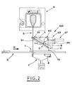
- the decorating device 100 comprises glaze conveying means 30, fit to intermittently intercept the aforesaid glaze film 5, during its free falling, for diverting a portion 10 thereof along an alternative path 11, while keeping it substantially unbroken, i.e. keeping its laminar conformation. Interception is made in a suitable phase relationship with the tiles 1 position on the conveyor 3.
- the conveying means 30 comprises a plate 31, which has a substantially rectangular shape, arranged crosswise as to the glaze film 5 flow.
- the plate 31 is supported by corresponding supporting members 33, inclined upstream to downstream as regards the above mentioned transporting direction W.
- the width of plate 31 is preferably substantially greater than the width of a tile 1, and it symmetrically exceeds the tile 1 borders. The reasons of that will appear evident later on in this description.
- the aforesaid tank 7 extends, in a longitudinal direction as to the conveyor 3, beyond the downstream edge of the plate 31, in order to collect a portion of the diverted glaze film 10 which falls from said edge.
- an auxiliary container 8 is provided, the width of which is substantially equal to the tiles width.
- the auxiliary container 8 is fit to collect the portion of the diverted glaze film 10, still polluted by the decorating product 6, which is not spread onto the tiles 1. It is moreover provided with a pipe, not shown, which allows the polluted glaze to be conveyed outside.
- the above mentioned supporting members 33 in the present embodiment, particularly comprise a pair of fixed guides 34, arranged sideways of the plate 31.
- a side supporting frame 35 and a carriage 36 are provided, this latter being mounted on the supporting frame 35 and fit to reciprocally roll in its own fixed guide 34.
- the glaze conveying means 30 moreover comprises actuating means 37, fit to reciprocally move the plate 31 between an idle position A (shown with dashed lines in figure 2) and an operating position B (shown with continuous lines in the same figure).
- the plate 31 In the above idle position A, the plate 31 doesn't matches the glaze film 5, and it leaves the same film to flow down to the tank 7. While in the operating position B, the plate 31 intercepts a central portion 10 of the glaze film 5 and diverts said portion 10 along the alternative path 11. Due to the above described shape of the plate 31, the whole alternative path 11 is located downstream of the glaze film 5, as to the transport direction W, and it intercepts the moving tiles 1 downstream of the original falling path of glaze film 5, at a glaze spreading line 15.
- the above mentioned actuating means 37 comprises, in the present embodiment, a pneumatic ram, having a stroke width sufficient to reciprocally move the plate 31 between the idle position A and the operating position B.
- the actuating means 37 could as well consist of a different known reciprocating device, e.g. a motor driven group consisting of a crank coupled with a corresponding rod.
- the present decorating device 100 moreover comprises glaze application means 40, fit to spray an amount of a decorating product 6 onto the diverted glaze film 10, while it is running on the alternative path 11 and before it is spread onto a tile 1.
- the decorating product 6 preferably consists of a glaze having different colour and/or composition of the one forming the diverted glaze film 10, but it could be any other known product, in a liquid or powdery state, suitable to be used for decorating tiles.
- the glaze application means 40 are arranged above the plate 31, in a visual relationship with the diverted glaze film 10, and they can consist of a conventional air-operated sprayer, as by example an airbrush, or of an airless sprayer, or of a kind of tube arranged crosswise as to the diverted glaze film 10, as well. This latter tube would be provided with a plurality of holes, fit to eject the decorating product 6 toward the diverted glaze film 10.
- sprayers are universally known to all people reasonably skilled in the art. Accordingly, they will not be described in details in the following. They can have a fixed or movable support, so as to make them movable, e.g., crosswise, and moreover providing them with driving means for driving them along a predefined path. It is also possible to mount several sprayers 40, loaded with decorating glazes 6 having different colours, and to use them separately or in combination, in order to obtain on the tiles 1 a greater number of decorating patterns.
- the sprayer 40 can eject the decorating glaze 6 at any direction matching the diverted glaze film 10.
- the decorating glaze 6 can be sprayed onto the diverted glaze film 10 perpendicularly to this latter, as well as at downstream or upstream directions as regards its falling direction. All these different directions of spraying will result in as many effects on the diverted glaze film 10 and, by consequence, as many decorating patterns on the tiles 1.
- the positional control of the tiles 1, as well as the plate 31 movements and the sprayer 40 operating, are made, in a mutual phase relationship, by means of an electronic control box, suitably connected to some positional transducers giving the correct tile position on the conveyor 3.
- plate 31 is held in its operating position B.
- the auxiliary container 8 is reciprocally movable, in a phase relationship with the tiles 1 position and with the operation of sprayer 40, between a collecting position C (shown with continuous lines in figure 6) and an idle position D (shown with dashed lines in the same figure). While in its collecting position C, the auxiliary container 8 intercepts the polluted portion of the diverted glaze film 10. If the auxiliary container 8 is held in its idle position D, it doesn't intercept the diverted glaze film 10, which has not been polluted by the sprayer 40, and which then flows undisturbed toward the tank 7.
- An actuating member 8a consisting of a pneumatic ram, is connected to the auxiliary container 8, in order to allow its reciprocal translation between positions C and D.
- the glaze film diverting means 30 comprises, besides the aforesaid plate 31, a further glazing head 50, arranged along the alternative path 11, just downstream from the plate 31.
- This further glazing head 50 is fit to receive the diverted glaze film 10 coming from the plate 3, to break it, and then to create it again just downstream.
- the further glazing head 50 is preferably an open glazing head, operated at atmospheric pressure.
- the glaze application means 40 is located inside the further glazing head 50 (see figure 4). More particularly, it consists of a glaze screw feeder 51, which comprises a pipe 52 containing an Archimedean screw 53.
- the screw feeder 51 extends inside the further glazing head 50, crosswise to the glaze film flow.
- Pipe 52 is provided with a series of suitably sized and spaced holes, fit for gradually release the decorating product 6. This latter is fed to the screw feeder 51 by means of a feeding pipe 54, preferably provided with a one-way valve.
- the decorating device 100 also comprises a tank 7 for glaze collecting and/or recycling, and an auxiliary container 8 for the polluted, non re-usable glaze.
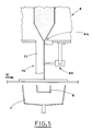
- the present decorating device 100 is provided with glaze conveying means 70 which comprises a supporting plate 71, extending downwards from the output slit 4a of the glazing head 4.
- the supporting plate 71 is an extension of the upstream wall of the aforesaid output slit 4a, so as to guide the glaze film 5, without break it, during the first part of its fall.
- the transverse width of the supporting plate 71 is significantly greater than the width of the tiles 1 to be glazed, and is preferably equal to the glaze film 5 width.
- the supporting plate 71 is preferably slightly inclined to downstream, as to the vertical free fall of the glaze film 5, so as to guarantee that this latter is well supported without a substantial modifications of its fall speed and thickness constancy.
- the supporting plate 71 can be also mounted vertically, or with a different angle of inclination, depending on the film glaze characteristics that it is intended to obtain. Normally, bigger angles of inclination lead to a slower, thicker glaze film 5.
- the support plate inclination can also made adjustable, by hinging it around an horizontal axis located at the output slit 4a, for optimising the glaze film characteristics according to different glaze density and viscosity values. This will depend, of course, on the kind of glaze which is used at a given time.
- the above described tank 7 and auxiliary container 8 are provided below the glazing head 4 and the conveyor 3, below the above described tank 7 and auxiliary container 8 are provided. Because the support plate is supposed to be held steady during the glazing operations, the auxiliary container 8 is made reciprocally movable, between a collecting position C and an idle position D, in a suitable phase relationship with the tiles position on the conveyor 3, as already described for the previous embodiments of the present invention.
- the glaze application means 40 for the present third embodiment, is substantially the same of that described for the first embodiment of the decorating device 100.
- the sprayer 40 could be advantageously mounted on the bottom face of the glazing head 4, downstream from the output slit 4a.
- the plate 31 when carried out with the decorating device 100 as from the aforesaid first embodiment, the plate 31 is moved between the above mentioned idle position A and operating position b, in a suitable phase relationship with the position of a corresponding tile 1, to be glazed and decorated, on the conveyor 3. More particularly, if no tiles are approaching the glaze spreading line 15, the plate 31 is held in its idle position A, and it doesn't intercept the glaze film 5. In this situation the glaze film 5 falls undisturbed and flows into the tank 7, from which it is recycled and sent to the glazing head 4.
- the plate 31 When a tile 1, transported by the conveyor 3, is just upstream from the falling plane of the glaze film 5, the plate 31 is driven to its operating position B, wherein it intercepts a portion of the glaze film 5 and diverts it through the alternative path 11.
- the plate 31 shape and its slope allow the diverted glaze film to be routed along the alternative path 11 without break it, i.e., while maintaining its laminar configuration.
- the plate length and the conveyor speed are chosen so that the diverted glaze film 10 reaches the transport plane, at the glaze spreading line 15, just when this latter is also reached by the front edge of the tile 1 to be glazed.
- the sprayer 40 is moreover actuated. This latter, depending on its configuration and setting, ejects one or more jets of decorating glaze 6 toward the diverted glaze film 10 supported by the plate 31.
- the timing sequence for actuating the sprayer 40, as well as its movements and other operating parameters, are suitably set according to different types of decorating patterns which are intended to obtain.
- the diverted glaze film 10 leaves the lower edge of plate 31, because of physical effects mostly depending on the glaze viscosity, there is a contraction in the same diverted glaze film 10, at its side borders. That is, the film transverse width at the glaze spreading line 15 is smaller than that of the glaze film portion diverted by the plate 31. For this reason the width of plate 31 must be significantly greater than the tile width. Only in this case the glaze film width at the glaze spreading line 15 will be equal or greater than the tile 1 width, and the diverted glaze film 10 will cover the whole tile 1.
- the plate 31 is held fixed in its operating position B (see figure 6) of continuously intercepting of the glaze film 5, and the auxiliary container 8 is reciprocally movable between a collecting position C and an idle position D. In this case, there is a continuous flow of diverted glaze film 10 along the alternative path 11.
- the auxiliary container While no tiles 1 are approaching the glaze spreading line 15, the auxiliary container is held in its idle position D, the sprayer 40 is idle as well, and the diverted glaze film 10 flows down to the tank 7.
- the sprayer 40 When a tile 1 approaches the glaze spreading line 15, the sprayer 40 is actuated, in a suitable phase relationship with the tile crossing of said line 15, for spraying a decorating pattern onto the diverted glaze film 10.
- the container 8 is then moved to its collecting position C, wherein it collects the glaze film portion which are not spread onto the tile 1, and which is still polluted by the decorating glaze 6 (practically, a glaze film portion which immediately follows the crossing of the glaze spreading line 15 by the rear edge of a tile).
- a further variant of the present method is carried out by the decorating device 100 according to its above described second embodiment.
- the diverted glaze film 10 leaves the downstream edge of the plate 31, it is conveyed into the aforesaid further glazing head 50, which breaks the glaze film by collecting it into its funnel.
- the screw feeder 51 is then operated, at a due time before the front edge of a tile 1 reaches the glaze spreading line 15, and a suitable amount of decorating glaze 6 flows into the funnel. This latter is partially mixed with the glaze already present inside the funnel.
- Both components flow out of the further glazing head, again in the form of a glaze film 10, wherein the distribution of decorating glaze 6 in the base glaze depends on the glaze releasing mode of the screw feeder 51. Finally, the output glaze film spreads on the tile 1.
- sprayer 40 is operated, according to pre-defined operating modes (which depend on the desired decorating patterns), for spraying the decorating glaze 6 on the supported glaze film.
- the spraying timing is of course synchronized with the time needed to a specific portion of glaze film for reaching the tile surface.
- the complete support provided to the glaze film 5 by the supporting plate 71 prevents that any breaks occur during the spraying phase, and allow the same glaze film 5 to leave the bottom edge of the supporting plate 71 unchanged, and carrying the decorating product 6.
- auxiliary container 8 is moved between its collecting position C and its idle position D, in a phase relationship with the tiles position and with the sprayer 40 operation, in the same way already described for the present method as from the variant of the first embodiment of the decorating device 100.
- the advantages which are attained by the present invention consist, first of all, in that the glaze film and the decorating glaze are simultaneously spread on the tile, subsequently to their mutual interaction and partial mixing. This allows a great number of new decorating effects and patterns to be obtained.
- a further advantage comes from the possibility to obtain on tiles, with the present method and decorating device, decorating effects which look very similar to visual effects and patterns typical of the natural stones.
- Another advantage is that said decorating effects can be indefinitely repeated, in a very similar form, on a number of tiles.
- Another advantage is that the most part of the glaze film which is not applied to the tiles is not polluted by the decorating glaze, and then it can be collected and reused without affecting the base colour of the subsequent tiles to be glazed.
Landscapes
- Chemical & Material Sciences (AREA)
- Engineering & Computer Science (AREA)
- Ceramic Engineering (AREA)
- Structural Engineering (AREA)
- Mechanical Engineering (AREA)
- Materials Engineering (AREA)
- Organic Chemistry (AREA)
- Inorganic Chemistry (AREA)
- Life Sciences & Earth Sciences (AREA)
- Sustainable Development (AREA)
- Devices For Post-Treatments, Processing, Supply, Discharge, And Other Processes (AREA)
Priority Applications (1)
| Application Number | Priority Date | Filing Date | Title |
|---|---|---|---|
| EP01118419A EP1281495A1 (fr) | 2001-07-31 | 2001-07-31 | Procédé pour décorer des carreaux et similaires, et dispositif pour la mise en oeuvre de ce procédé |
Applications Claiming Priority (1)
| Application Number | Priority Date | Filing Date | Title |
|---|---|---|---|
| EP01118419A EP1281495A1 (fr) | 2001-07-31 | 2001-07-31 | Procédé pour décorer des carreaux et similaires, et dispositif pour la mise en oeuvre de ce procédé |
Publications (1)
| Publication Number | Publication Date |
|---|---|
| EP1281495A1 true EP1281495A1 (fr) | 2003-02-05 |
Family
ID=8178197
Family Applications (1)
| Application Number | Title | Priority Date | Filing Date |
|---|---|---|---|
| EP01118419A Withdrawn EP1281495A1 (fr) | 2001-07-31 | 2001-07-31 | Procédé pour décorer des carreaux et similaires, et dispositif pour la mise en oeuvre de ce procédé |
Country Status (1)
| Country | Link |
|---|---|
| EP (1) | EP1281495A1 (fr) |
Cited By (12)
| Publication number | Priority date | Publication date | Assignee | Title |
|---|---|---|---|---|
| CN106938492A (zh) * | 2017-04-27 | 2017-07-11 | 佛山市东鹏陶瓷有限公司 | 一种釉线智能节釉装置 |
| CN107186871A (zh) * | 2017-07-14 | 2017-09-22 | 蔡惠文 | 一种陶瓷产品生产用气动式调节喷釉设备 |
| CN107297813A (zh) * | 2017-07-14 | 2017-10-27 | 蔡惠文 | 一种陶瓷产品生产用可调式喷釉设备 |
| IT201700072025A1 (it) * | 2017-06-27 | 2018-12-27 | Air Power Group S P A | Metodo e apparecchiatura per la preparazione di una miscela di smalto per un impianto di smaltatura |
| CN109676768A (zh) * | 2019-02-28 | 2019-04-26 | 佛山市东鹏陶瓷有限公司 | 一种布料系统 |
| CN110722669A (zh) * | 2019-12-11 | 2020-01-24 | 禹州市神器钧窑有限公司 | 一种钧瓷旋转喷釉装置 |
| CN111993552A (zh) * | 2020-09-05 | 2020-11-27 | 曹凯悦 | 一种瓷砖生产表面施釉方法 |
| IT202000004681A1 (it) * | 2020-03-05 | 2021-09-05 | Matteo Ferrario | Macchina per la smaltatura di piastrelle |
| CN113386249A (zh) * | 2021-06-23 | 2021-09-14 | 上海工艺美术职业学院 | 一种用于陶瓷加工的喷釉装置 |
| IT202100011834A1 (it) * | 2021-05-10 | 2022-11-10 | Air Power Group S P A | Dispositivo per l'interruzione del velo di smalto in uscita da una testa di velatura |
| CN116175749A (zh) * | 2023-02-08 | 2023-05-30 | 龙泉市瓯青源青瓷文化有限公司 | 一种利用金矿矿尾砂制备茶叶末釉的加工设备 |
| CN117485903A (zh) * | 2023-11-09 | 2024-02-02 | 淄博大川陶瓷科技有限公司 | 瓷砖淋釉传送机构及淋釉系统 |
Citations (3)
| Publication number | Priority date | Publication date | Assignee | Title |
|---|---|---|---|---|
| GB2171402A (en) * | 1985-02-21 | 1986-08-28 | Marazzi Ceramica | Process and apparatus for producing glazed ceramic tiles, and tiles so obtained |
| JPH0532471A (ja) * | 1991-07-26 | 1993-02-09 | Inax Corp | 施釉装置 |
| JPH0920549A (ja) * | 1995-06-29 | 1997-01-21 | Sugiura Seitoushiyo:Kk | 模様付きタイルの製造方法及びその製造装置 |
-
2001
- 2001-07-31 EP EP01118419A patent/EP1281495A1/fr not_active Withdrawn
Patent Citations (3)
| Publication number | Priority date | Publication date | Assignee | Title |
|---|---|---|---|---|
| GB2171402A (en) * | 1985-02-21 | 1986-08-28 | Marazzi Ceramica | Process and apparatus for producing glazed ceramic tiles, and tiles so obtained |
| JPH0532471A (ja) * | 1991-07-26 | 1993-02-09 | Inax Corp | 施釉装置 |
| JPH0920549A (ja) * | 1995-06-29 | 1997-01-21 | Sugiura Seitoushiyo:Kk | 模様付きタイルの製造方法及びその製造装置 |
Non-Patent Citations (2)
| Title |
|---|
| PATENT ABSTRACTS OF JAPAN vol. 17, no. 321 (C - 1072) 18 June 1993 (1993-06-18) * |
| PATENT ABSTRACTS OF JAPAN vol. 1997, no. 5 30 May 1997 (1997-05-30) * |
Cited By (18)
| Publication number | Priority date | Publication date | Assignee | Title |
|---|---|---|---|---|
| CN106938492B (zh) * | 2017-04-27 | 2023-08-29 | 佛山市东鹏陶瓷有限公司 | 一种釉线智能节釉装置 |
| CN106938492A (zh) * | 2017-04-27 | 2017-07-11 | 佛山市东鹏陶瓷有限公司 | 一种釉线智能节釉装置 |
| IT201700072025A1 (it) * | 2017-06-27 | 2018-12-27 | Air Power Group S P A | Metodo e apparecchiatura per la preparazione di una miscela di smalto per un impianto di smaltatura |
| EP3421203A1 (fr) * | 2017-06-27 | 2019-01-02 | Air Power Group S.p.A. | Procédé et dispositif de preparation d`une glacure |
| CN107186871A (zh) * | 2017-07-14 | 2017-09-22 | 蔡惠文 | 一种陶瓷产品生产用气动式调节喷釉设备 |
| CN107297813A (zh) * | 2017-07-14 | 2017-10-27 | 蔡惠文 | 一种陶瓷产品生产用可调式喷釉设备 |
| CN109676768A (zh) * | 2019-02-28 | 2019-04-26 | 佛山市东鹏陶瓷有限公司 | 一种布料系统 |
| CN109676768B (zh) * | 2019-02-28 | 2023-09-12 | 佛山市东鹏陶瓷有限公司 | 一种布料系统 |
| CN110722669A (zh) * | 2019-12-11 | 2020-01-24 | 禹州市神器钧窑有限公司 | 一种钧瓷旋转喷釉装置 |
| IT202000004681A1 (it) * | 2020-03-05 | 2021-09-05 | Matteo Ferrario | Macchina per la smaltatura di piastrelle |
| CN111993552B (zh) * | 2020-09-05 | 2021-04-02 | 山东顺为陶瓷有限公司 | 一种瓷砖生产表面施釉方法 |
| CN111993552A (zh) * | 2020-09-05 | 2020-11-27 | 曹凯悦 | 一种瓷砖生产表面施釉方法 |
| IT202100011834A1 (it) * | 2021-05-10 | 2022-11-10 | Air Power Group S P A | Dispositivo per l'interruzione del velo di smalto in uscita da una testa di velatura |
| CN113386249A (zh) * | 2021-06-23 | 2021-09-14 | 上海工艺美术职业学院 | 一种用于陶瓷加工的喷釉装置 |
| CN116175749A (zh) * | 2023-02-08 | 2023-05-30 | 龙泉市瓯青源青瓷文化有限公司 | 一种利用金矿矿尾砂制备茶叶末釉的加工设备 |
| CN116175749B (zh) * | 2023-02-08 | 2025-08-26 | 龙泉市瓯青源青瓷文化有限公司 | 一种利用金矿矿尾砂制备茶叶末釉的加工设备 |
| CN117485903A (zh) * | 2023-11-09 | 2024-02-02 | 淄博大川陶瓷科技有限公司 | 瓷砖淋釉传送机构及淋釉系统 |
| CN117485903B (zh) * | 2023-11-09 | 2024-05-24 | 淄博大川陶瓷科技有限公司 | 瓷砖淋釉传送机构及淋釉系统 |
Similar Documents
| Publication | Publication Date | Title |
|---|---|---|
| EP1281495A1 (fr) | Procédé pour décorer des carreaux et similaires, et dispositif pour la mise en oeuvre de ce procédé | |
| US4178340A (en) | Method and apparatus for making concrete brick having antique appearance | |
| CN107206623B (zh) | 用于生产具有色彩效果的板的可编程的站和设备 | |
| US8337947B2 (en) | Decorating with powder material | |
| JPH07112553B2 (ja) | 縁部塗被装置 | |
| CN110636930B (zh) | 用于陶瓷制品的表面装饰的方法和机器 | |
| EP3944902A1 (fr) | Dispositif et installation de glaçurage de produits | |
| EP3238900B1 (fr) | Dispositif a axes multiples pour appliquer des produits de decoration sur des objets ceramiques, et methode d'application desdites produits | |
| CN113165205B (zh) | 用于瓷砖的干法装饰的机器 | |
| CN113490809B (zh) | 用于颗粒或粉末材料的分配杆 | |
| US5942181A (en) | Method for texturizing the face of concrete products | |
| EP1162047B1 (fr) | Dispositif pour distribuer suivant un dessin déterminé des matériaux pulvérulents sur un support | |
| EP0941826A2 (fr) | Méthode pour la fabrication d'un carreau décoré , dispositif correspondant pour l'alimentation des moules de pressage et carreau ainsi obtenu | |
| US12318962B2 (en) | Machine and method for decorating items with granular materials | |
| US4229156A (en) | Apparatus for making concrete brick having antique appearance | |
| KR20080083691A (ko) | 베이닝 및/또는 스팟 효과와 같은 채색 효과를 가지는슬래브 또는 타일의 형태인 물품을 제조하기 위한 방법 및장치 | |
| JPH06157167A (ja) | タイルの施釉方法及びその施釉装置 | |
| CN111719825A (zh) | 一种建筑外墙喷涂机 | |
| EP1063068A2 (fr) | Procédé de revêtement décoratif de surfaces, en particulier de carreaux, et dispositif de mise en oeuvre dudit procédé | |
| WO2024165965A1 (fr) | Dispositif d'émaillage d'objets tels que des dalles et carreaux en céramique | |
| US12319055B2 (en) | Ink jet head for emission of ceramic enamel | |
| IT1314623B1 (it) | Metodo e dispositivo per muovere materiale sciolto | |
| EP4467344A1 (fr) | Machine et procédé pour la décoration d'articles manufacturés en céramique | |
| EP4321258B1 (fr) | Piece d'equipement de glaçage d'articles manufacturés | |
| IT1314624B1 (it) | Metodo e dispositivo per apporre materiale sciolto |
Legal Events
| Date | Code | Title | Description |
|---|---|---|---|
| PUAI | Public reference made under article 153(3) epc to a published international application that has entered the european phase |
Free format text: ORIGINAL CODE: 0009012 |
|
| AK | Designated contracting states |
Designated state(s): AT BE CH CY DE DK ES FI FR GB GR IE IT LI LU MC NL PT SE TR |
|
| AX | Request for extension of the european patent |
Extension state: AL LT LV MK RO SI |
|
| 17P | Request for examination filed |
Effective date: 20030730 |
|
| AKX | Designation fees paid |
Designated state(s): DE ES IT |
|
| GRAP | Despatch of communication of intention to grant a patent |
Free format text: ORIGINAL CODE: EPIDOSNIGR1 |
|
| STAA | Information on the status of an ep patent application or granted ep patent |
Free format text: STATUS: THE APPLICATION IS DEEMED TO BE WITHDRAWN |
|
| 18D | Application deemed to be withdrawn |
Effective date: 20060707 |