EP1281562A2 - Dispositif et méthode de commande d'entraínement pour un véhicule du type hybride et programme correspondante - Google Patents
Dispositif et méthode de commande d'entraínement pour un véhicule du type hybride et programme correspondante Download PDFInfo
- Publication number
- EP1281562A2 EP1281562A2 EP02017229A EP02017229A EP1281562A2 EP 1281562 A2 EP1281562 A2 EP 1281562A2 EP 02017229 A EP02017229 A EP 02017229A EP 02017229 A EP02017229 A EP 02017229A EP 1281562 A2 EP1281562 A2 EP 1281562A2
- Authority
- EP
- European Patent Office
- Prior art keywords
- generator
- voltage
- drive motor
- torque
- rotation speed
- Prior art date
- Legal status (The legal status is an assumption and is not a legal conclusion. Google has not performed a legal analysis and makes no representation as to the accuracy of the status listed.)
- Granted
Links
Images








Classifications
-
- B—PERFORMING OPERATIONS; TRANSPORTING
- B60—VEHICLES IN GENERAL
- B60W—CONJOINT CONTROL OF VEHICLE SUB-UNITS OF DIFFERENT TYPE OR DIFFERENT FUNCTION; CONTROL SYSTEMS SPECIALLY ADAPTED FOR HYBRID VEHICLES; ROAD VEHICLE DRIVE CONTROL SYSTEMS FOR PURPOSES NOT RELATED TO THE CONTROL OF A PARTICULAR SUB-UNIT
- B60W20/00—Control systems specially adapted for hybrid vehicles
- B60W20/10—Controlling the power contribution of each of the prime movers to meet required power demand
-
- B—PERFORMING OPERATIONS; TRANSPORTING
- B60—VEHICLES IN GENERAL
- B60K—ARRANGEMENT OR MOUNTING OF PROPULSION UNITS OR OF TRANSMISSIONS IN VEHICLES; ARRANGEMENT OR MOUNTING OF PLURAL DIVERSE PRIME-MOVERS IN VEHICLES; AUXILIARY DRIVES FOR VEHICLES; INSTRUMENTATION OR DASHBOARDS FOR VEHICLES; ARRANGEMENTS IN CONNECTION WITH COOLING, AIR INTAKE, GAS EXHAUST OR FUEL SUPPLY OF PROPULSION UNITS IN VEHICLES
- B60K6/00—Arrangement or mounting of plural diverse prime-movers for mutual or common propulsion, e.g. hybrid propulsion systems comprising electric motors and internal combustion engines
- B60K6/20—Arrangement or mounting of plural diverse prime-movers for mutual or common propulsion, e.g. hybrid propulsion systems comprising electric motors and internal combustion engines the prime-movers consisting of electric motors and internal combustion engines, e.g. HEVs
- B60K6/22—Arrangement or mounting of plural diverse prime-movers for mutual or common propulsion, e.g. hybrid propulsion systems comprising electric motors and internal combustion engines the prime-movers consisting of electric motors and internal combustion engines, e.g. HEVs characterised by apparatus, components or means specially adapted for HEVs
- B60K6/36—Arrangement or mounting of plural diverse prime-movers for mutual or common propulsion, e.g. hybrid propulsion systems comprising electric motors and internal combustion engines the prime-movers consisting of electric motors and internal combustion engines, e.g. HEVs characterised by apparatus, components or means specially adapted for HEVs characterised by the transmission gearings
- B60K6/365—Arrangement or mounting of plural diverse prime-movers for mutual or common propulsion, e.g. hybrid propulsion systems comprising electric motors and internal combustion engines the prime-movers consisting of electric motors and internal combustion engines, e.g. HEVs characterised by apparatus, components or means specially adapted for HEVs characterised by the transmission gearings with the gears having orbital motion
-
- B—PERFORMING OPERATIONS; TRANSPORTING
- B60—VEHICLES IN GENERAL
- B60K—ARRANGEMENT OR MOUNTING OF PROPULSION UNITS OR OF TRANSMISSIONS IN VEHICLES; ARRANGEMENT OR MOUNTING OF PLURAL DIVERSE PRIME-MOVERS IN VEHICLES; AUXILIARY DRIVES FOR VEHICLES; INSTRUMENTATION OR DASHBOARDS FOR VEHICLES; ARRANGEMENTS IN CONNECTION WITH COOLING, AIR INTAKE, GAS EXHAUST OR FUEL SUPPLY OF PROPULSION UNITS IN VEHICLES
- B60K6/00—Arrangement or mounting of plural diverse prime-movers for mutual or common propulsion, e.g. hybrid propulsion systems comprising electric motors and internal combustion engines
- B60K6/20—Arrangement or mounting of plural diverse prime-movers for mutual or common propulsion, e.g. hybrid propulsion systems comprising electric motors and internal combustion engines the prime-movers consisting of electric motors and internal combustion engines, e.g. HEVs
- B60K6/42—Arrangement or mounting of plural diverse prime-movers for mutual or common propulsion, e.g. hybrid propulsion systems comprising electric motors and internal combustion engines the prime-movers consisting of electric motors and internal combustion engines, e.g. HEVs characterised by the architecture of the hybrid electric vehicle
- B60K6/44—Series-parallel type
- B60K6/445—Differential gearing distribution type
-
- B—PERFORMING OPERATIONS; TRANSPORTING
- B60—VEHICLES IN GENERAL
- B60L—PROPULSION OF ELECTRICALLY-PROPELLED VEHICLES; SUPPLYING ELECTRIC POWER FOR AUXILIARY EQUIPMENT OF ELECTRICALLY-PROPELLED VEHICLES; ELECTRODYNAMIC BRAKE SYSTEMS FOR VEHICLES IN GENERAL; MAGNETIC SUSPENSION OR LEVITATION FOR VEHICLES; MONITORING OPERATING VARIABLES OF ELECTRICALLY-PROPELLED VEHICLES; ELECTRIC SAFETY DEVICES FOR ELECTRICALLY-PROPELLED VEHICLES
- B60L15/00—Methods, circuits, or devices for controlling the traction-motor speed of electrically-propelled vehicles
- B60L15/20—Methods, circuits, or devices for controlling the traction-motor speed of electrically-propelled vehicles for control of the vehicle or its driving motor to achieve a desired performance, e.g. speed, torque, programmed variation of speed
-
- B—PERFORMING OPERATIONS; TRANSPORTING
- B60—VEHICLES IN GENERAL
- B60L—PROPULSION OF ELECTRICALLY-PROPELLED VEHICLES; SUPPLYING ELECTRIC POWER FOR AUXILIARY EQUIPMENT OF ELECTRICALLY-PROPELLED VEHICLES; ELECTRODYNAMIC BRAKE SYSTEMS FOR VEHICLES IN GENERAL; MAGNETIC SUSPENSION OR LEVITATION FOR VEHICLES; MONITORING OPERATING VARIABLES OF ELECTRICALLY-PROPELLED VEHICLES; ELECTRIC SAFETY DEVICES FOR ELECTRICALLY-PROPELLED VEHICLES
- B60L3/00—Electric devices on electrically-propelled vehicles for safety purposes; Monitoring operating variables, e.g. speed, deceleration or energy consumption
- B60L3/0023—Detecting, eliminating, remedying or compensating for drive train abnormalities, e.g. failures within the drive train
- B60L3/0038—Detecting, eliminating, remedying or compensating for drive train abnormalities, e.g. failures within the drive train relating to sensors
-
- B—PERFORMING OPERATIONS; TRANSPORTING
- B60—VEHICLES IN GENERAL
- B60L—PROPULSION OF ELECTRICALLY-PROPELLED VEHICLES; SUPPLYING ELECTRIC POWER FOR AUXILIARY EQUIPMENT OF ELECTRICALLY-PROPELLED VEHICLES; ELECTRODYNAMIC BRAKE SYSTEMS FOR VEHICLES IN GENERAL; MAGNETIC SUSPENSION OR LEVITATION FOR VEHICLES; MONITORING OPERATING VARIABLES OF ELECTRICALLY-PROPELLED VEHICLES; ELECTRIC SAFETY DEVICES FOR ELECTRICALLY-PROPELLED VEHICLES
- B60L3/00—Electric devices on electrically-propelled vehicles for safety purposes; Monitoring operating variables, e.g. speed, deceleration or energy consumption
- B60L3/0092—Electric devices on electrically-propelled vehicles for safety purposes; Monitoring operating variables, e.g. speed, deceleration or energy consumption with use of redundant elements for safety purposes
-
- B—PERFORMING OPERATIONS; TRANSPORTING
- B60—VEHICLES IN GENERAL
- B60L—PROPULSION OF ELECTRICALLY-PROPELLED VEHICLES; SUPPLYING ELECTRIC POWER FOR AUXILIARY EQUIPMENT OF ELECTRICALLY-PROPELLED VEHICLES; ELECTRODYNAMIC BRAKE SYSTEMS FOR VEHICLES IN GENERAL; MAGNETIC SUSPENSION OR LEVITATION FOR VEHICLES; MONITORING OPERATING VARIABLES OF ELECTRICALLY-PROPELLED VEHICLES; ELECTRIC SAFETY DEVICES FOR ELECTRICALLY-PROPELLED VEHICLES
- B60L50/00—Electric propulsion with power supplied within the vehicle
- B60L50/10—Electric propulsion with power supplied within the vehicle using propulsion power supplied by engine-driven generators, e.g. generators driven by combustion engines
- B60L50/16—Electric propulsion with power supplied within the vehicle using propulsion power supplied by engine-driven generators, e.g. generators driven by combustion engines with provision for separate direct mechanical propulsion
-
- B—PERFORMING OPERATIONS; TRANSPORTING
- B60—VEHICLES IN GENERAL
- B60L—PROPULSION OF ELECTRICALLY-PROPELLED VEHICLES; SUPPLYING ELECTRIC POWER FOR AUXILIARY EQUIPMENT OF ELECTRICALLY-PROPELLED VEHICLES; ELECTRODYNAMIC BRAKE SYSTEMS FOR VEHICLES IN GENERAL; MAGNETIC SUSPENSION OR LEVITATION FOR VEHICLES; MONITORING OPERATING VARIABLES OF ELECTRICALLY-PROPELLED VEHICLES; ELECTRIC SAFETY DEVICES FOR ELECTRICALLY-PROPELLED VEHICLES
- B60L50/00—Electric propulsion with power supplied within the vehicle
- B60L50/50—Electric propulsion with power supplied within the vehicle using propulsion power supplied by batteries or fuel cells
- B60L50/60—Electric propulsion with power supplied within the vehicle using propulsion power supplied by batteries or fuel cells using power supplied by batteries
- B60L50/61—Electric propulsion with power supplied within the vehicle using propulsion power supplied by batteries or fuel cells using power supplied by batteries by batteries charged by engine-driven generators, e.g. series hybrid electric vehicles
-
- B—PERFORMING OPERATIONS; TRANSPORTING
- B60—VEHICLES IN GENERAL
- B60W—CONJOINT CONTROL OF VEHICLE SUB-UNITS OF DIFFERENT TYPE OR DIFFERENT FUNCTION; CONTROL SYSTEMS SPECIALLY ADAPTED FOR HYBRID VEHICLES; ROAD VEHICLE DRIVE CONTROL SYSTEMS FOR PURPOSES NOT RELATED TO THE CONTROL OF A PARTICULAR SUB-UNIT
- B60W10/00—Conjoint control of vehicle sub-units of different type or different function
- B60W10/04—Conjoint control of vehicle sub-units of different type or different function including control of propulsion units
- B60W10/06—Conjoint control of vehicle sub-units of different type or different function including control of propulsion units including control of combustion engines
-
- B—PERFORMING OPERATIONS; TRANSPORTING
- B60—VEHICLES IN GENERAL
- B60W—CONJOINT CONTROL OF VEHICLE SUB-UNITS OF DIFFERENT TYPE OR DIFFERENT FUNCTION; CONTROL SYSTEMS SPECIALLY ADAPTED FOR HYBRID VEHICLES; ROAD VEHICLE DRIVE CONTROL SYSTEMS FOR PURPOSES NOT RELATED TO THE CONTROL OF A PARTICULAR SUB-UNIT
- B60W10/00—Conjoint control of vehicle sub-units of different type or different function
- B60W10/04—Conjoint control of vehicle sub-units of different type or different function including control of propulsion units
- B60W10/08—Conjoint control of vehicle sub-units of different type or different function including control of propulsion units including control of electric propulsion units, e.g. motors or generators
-
- B—PERFORMING OPERATIONS; TRANSPORTING
- B60—VEHICLES IN GENERAL
- B60W—CONJOINT CONTROL OF VEHICLE SUB-UNITS OF DIFFERENT TYPE OR DIFFERENT FUNCTION; CONTROL SYSTEMS SPECIALLY ADAPTED FOR HYBRID VEHICLES; ROAD VEHICLE DRIVE CONTROL SYSTEMS FOR PURPOSES NOT RELATED TO THE CONTROL OF A PARTICULAR SUB-UNIT
- B60W10/00—Conjoint control of vehicle sub-units of different type or different function
- B60W10/24—Conjoint control of vehicle sub-units of different type or different function including control of energy storage means
-
- B—PERFORMING OPERATIONS; TRANSPORTING
- B60—VEHICLES IN GENERAL
- B60W—CONJOINT CONTROL OF VEHICLE SUB-UNITS OF DIFFERENT TYPE OR DIFFERENT FUNCTION; CONTROL SYSTEMS SPECIALLY ADAPTED FOR HYBRID VEHICLES; ROAD VEHICLE DRIVE CONTROL SYSTEMS FOR PURPOSES NOT RELATED TO THE CONTROL OF A PARTICULAR SUB-UNIT
- B60W10/00—Conjoint control of vehicle sub-units of different type or different function
- B60W10/24—Conjoint control of vehicle sub-units of different type or different function including control of energy storage means
- B60W10/26—Conjoint control of vehicle sub-units of different type or different function including control of energy storage means for electrical energy, e.g. batteries or capacitors
-
- B—PERFORMING OPERATIONS; TRANSPORTING
- B60—VEHICLES IN GENERAL
- B60W—CONJOINT CONTROL OF VEHICLE SUB-UNITS OF DIFFERENT TYPE OR DIFFERENT FUNCTION; CONTROL SYSTEMS SPECIALLY ADAPTED FOR HYBRID VEHICLES; ROAD VEHICLE DRIVE CONTROL SYSTEMS FOR PURPOSES NOT RELATED TO THE CONTROL OF A PARTICULAR SUB-UNIT
- B60W20/00—Control systems specially adapted for hybrid vehicles
-
- B—PERFORMING OPERATIONS; TRANSPORTING
- B60—VEHICLES IN GENERAL
- B60L—PROPULSION OF ELECTRICALLY-PROPELLED VEHICLES; SUPPLYING ELECTRIC POWER FOR AUXILIARY EQUIPMENT OF ELECTRICALLY-PROPELLED VEHICLES; ELECTRODYNAMIC BRAKE SYSTEMS FOR VEHICLES IN GENERAL; MAGNETIC SUSPENSION OR LEVITATION FOR VEHICLES; MONITORING OPERATING VARIABLES OF ELECTRICALLY-PROPELLED VEHICLES; ELECTRIC SAFETY DEVICES FOR ELECTRICALLY-PROPELLED VEHICLES
- B60L2240/00—Control parameters of input or output; Target parameters
- B60L2240/10—Vehicle control parameters
- B60L2240/36—Temperature of vehicle components or parts
-
- B—PERFORMING OPERATIONS; TRANSPORTING
- B60—VEHICLES IN GENERAL
- B60W—CONJOINT CONTROL OF VEHICLE SUB-UNITS OF DIFFERENT TYPE OR DIFFERENT FUNCTION; CONTROL SYSTEMS SPECIALLY ADAPTED FOR HYBRID VEHICLES; ROAD VEHICLE DRIVE CONTROL SYSTEMS FOR PURPOSES NOT RELATED TO THE CONTROL OF A PARTICULAR SUB-UNIT
- B60W2510/00—Input parameters relating to a particular sub-units
- B60W2510/24—Energy storage means
- B60W2510/242—Energy storage means for electrical energy
-
- B—PERFORMING OPERATIONS; TRANSPORTING
- B60—VEHICLES IN GENERAL
- B60W—CONJOINT CONTROL OF VEHICLE SUB-UNITS OF DIFFERENT TYPE OR DIFFERENT FUNCTION; CONTROL SYSTEMS SPECIALLY ADAPTED FOR HYBRID VEHICLES; ROAD VEHICLE DRIVE CONTROL SYSTEMS FOR PURPOSES NOT RELATED TO THE CONTROL OF A PARTICULAR SUB-UNIT
- B60W2510/00—Input parameters relating to a particular sub-units
- B60W2510/24—Energy storage means
- B60W2510/242—Energy storage means for electrical energy
- B60W2510/244—Charge state
-
- B—PERFORMING OPERATIONS; TRANSPORTING
- B60—VEHICLES IN GENERAL
- B60W—CONJOINT CONTROL OF VEHICLE SUB-UNITS OF DIFFERENT TYPE OR DIFFERENT FUNCTION; CONTROL SYSTEMS SPECIALLY ADAPTED FOR HYBRID VEHICLES; ROAD VEHICLE DRIVE CONTROL SYSTEMS FOR PURPOSES NOT RELATED TO THE CONTROL OF A PARTICULAR SUB-UNIT
- B60W2710/00—Output or target parameters relating to a particular sub-units
- B60W2710/24—Energy storage means
- B60W2710/242—Energy storage means for electrical energy
-
- F—MECHANICAL ENGINEERING; LIGHTING; HEATING; WEAPONS; BLASTING
- F16—ENGINEERING ELEMENTS AND UNITS; GENERAL MEASURES FOR PRODUCING AND MAINTAINING EFFECTIVE FUNCTIONING OF MACHINES OR INSTALLATIONS; THERMAL INSULATION IN GENERAL
- F16H—GEARING
- F16H37/00—Combinations of mechanical gearings, not provided for in groups F16H1/00 - F16H35/00
- F16H37/02—Combinations of mechanical gearings, not provided for in groups F16H1/00 - F16H35/00 comprising essentially only toothed or friction gearings
- F16H37/06—Combinations of mechanical gearings, not provided for in groups F16H1/00 - F16H35/00 comprising essentially only toothed or friction gearings with a plurality of driving or driven shafts; with arrangements for dividing torque between two or more intermediate shafts
- F16H37/08—Combinations of mechanical gearings, not provided for in groups F16H1/00 - F16H35/00 comprising essentially only toothed or friction gearings with a plurality of driving or driven shafts; with arrangements for dividing torque between two or more intermediate shafts with differential gearing
- F16H37/0833—Combinations of mechanical gearings, not provided for in groups F16H1/00 - F16H35/00 comprising essentially only toothed or friction gearings with a plurality of driving or driven shafts; with arrangements for dividing torque between two or more intermediate shafts with differential gearing with arrangements for dividing torque between two or more intermediate shafts, i.e. with two or more internal power paths
- F16H37/084—Combinations of mechanical gearings, not provided for in groups F16H1/00 - F16H35/00 comprising essentially only toothed or friction gearings with a plurality of driving or driven shafts; with arrangements for dividing torque between two or more intermediate shafts with differential gearing with arrangements for dividing torque between two or more intermediate shafts, i.e. with two or more internal power paths at least one power path being a continuously variable transmission, i.e. CVT
- F16H2037/0866—Power-split transmissions with distributing differentials, with the output of the CVT connected or connectable to the output shaft
-
- Y—GENERAL TAGGING OF NEW TECHNOLOGICAL DEVELOPMENTS; GENERAL TAGGING OF CROSS-SECTIONAL TECHNOLOGIES SPANNING OVER SEVERAL SECTIONS OF THE IPC; TECHNICAL SUBJECTS COVERED BY FORMER USPC CROSS-REFERENCE ART COLLECTIONS [XRACs] AND DIGESTS
- Y02—TECHNOLOGIES OR APPLICATIONS FOR MITIGATION OR ADAPTATION AGAINST CLIMATE CHANGE
- Y02T—CLIMATE CHANGE MITIGATION TECHNOLOGIES RELATED TO TRANSPORTATION
- Y02T10/00—Road transport of goods or passengers
- Y02T10/60—Other road transportation technologies with climate change mitigation effect
- Y02T10/62—Hybrid vehicles
-
- Y—GENERAL TAGGING OF NEW TECHNOLOGICAL DEVELOPMENTS; GENERAL TAGGING OF CROSS-SECTIONAL TECHNOLOGIES SPANNING OVER SEVERAL SECTIONS OF THE IPC; TECHNICAL SUBJECTS COVERED BY FORMER USPC CROSS-REFERENCE ART COLLECTIONS [XRACs] AND DIGESTS
- Y02—TECHNOLOGIES OR APPLICATIONS FOR MITIGATION OR ADAPTATION AGAINST CLIMATE CHANGE
- Y02T—CLIMATE CHANGE MITIGATION TECHNOLOGIES RELATED TO TRANSPORTATION
- Y02T10/00—Road transport of goods or passengers
- Y02T10/60—Other road transportation technologies with climate change mitigation effect
- Y02T10/64—Electric machine technologies in electromobility
-
- Y—GENERAL TAGGING OF NEW TECHNOLOGICAL DEVELOPMENTS; GENERAL TAGGING OF CROSS-SECTIONAL TECHNOLOGIES SPANNING OVER SEVERAL SECTIONS OF THE IPC; TECHNICAL SUBJECTS COVERED BY FORMER USPC CROSS-REFERENCE ART COLLECTIONS [XRACs] AND DIGESTS
- Y02—TECHNOLOGIES OR APPLICATIONS FOR MITIGATION OR ADAPTATION AGAINST CLIMATE CHANGE
- Y02T—CLIMATE CHANGE MITIGATION TECHNOLOGIES RELATED TO TRANSPORTATION
- Y02T10/00—Road transport of goods or passengers
- Y02T10/60—Other road transportation technologies with climate change mitigation effect
- Y02T10/70—Energy storage systems for electromobility, e.g. batteries
-
- Y—GENERAL TAGGING OF NEW TECHNOLOGICAL DEVELOPMENTS; GENERAL TAGGING OF CROSS-SECTIONAL TECHNOLOGIES SPANNING OVER SEVERAL SECTIONS OF THE IPC; TECHNICAL SUBJECTS COVERED BY FORMER USPC CROSS-REFERENCE ART COLLECTIONS [XRACs] AND DIGESTS
- Y02—TECHNOLOGIES OR APPLICATIONS FOR MITIGATION OR ADAPTATION AGAINST CLIMATE CHANGE
- Y02T—CLIMATE CHANGE MITIGATION TECHNOLOGIES RELATED TO TRANSPORTATION
- Y02T10/00—Road transport of goods or passengers
- Y02T10/60—Other road transportation technologies with climate change mitigation effect
- Y02T10/7072—Electromobility specific charging systems or methods for batteries, ultracapacitors, supercapacitors or double-layer capacitors
-
- Y—GENERAL TAGGING OF NEW TECHNOLOGICAL DEVELOPMENTS; GENERAL TAGGING OF CROSS-SECTIONAL TECHNOLOGIES SPANNING OVER SEVERAL SECTIONS OF THE IPC; TECHNICAL SUBJECTS COVERED BY FORMER USPC CROSS-REFERENCE ART COLLECTIONS [XRACs] AND DIGESTS
- Y02—TECHNOLOGIES OR APPLICATIONS FOR MITIGATION OR ADAPTATION AGAINST CLIMATE CHANGE
- Y02T—CLIMATE CHANGE MITIGATION TECHNOLOGIES RELATED TO TRANSPORTATION
- Y02T10/00—Road transport of goods or passengers
- Y02T10/60—Other road transportation technologies with climate change mitigation effect
- Y02T10/72—Electric energy management in electromobility
-
- Y—GENERAL TAGGING OF NEW TECHNOLOGICAL DEVELOPMENTS; GENERAL TAGGING OF CROSS-SECTIONAL TECHNOLOGIES SPANNING OVER SEVERAL SECTIONS OF THE IPC; TECHNICAL SUBJECTS COVERED BY FORMER USPC CROSS-REFERENCE ART COLLECTIONS [XRACs] AND DIGESTS
- Y10—TECHNICAL SUBJECTS COVERED BY FORMER USPC
- Y10S—TECHNICAL SUBJECTS COVERED BY FORMER USPC CROSS-REFERENCE ART COLLECTIONS [XRACs] AND DIGESTS
- Y10S903/00—Hybrid electric vehicles, HEVS
- Y10S903/902—Prime movers comprising electrical and internal combustion motors
- Y10S903/903—Prime movers comprising electrical and internal combustion motors having energy storing means, e.g. battery, capacitor
- Y10S903/904—Component specially adapted for hev
-
- Y—GENERAL TAGGING OF NEW TECHNOLOGICAL DEVELOPMENTS; GENERAL TAGGING OF CROSS-SECTIONAL TECHNOLOGIES SPANNING OVER SEVERAL SECTIONS OF THE IPC; TECHNICAL SUBJECTS COVERED BY FORMER USPC CROSS-REFERENCE ART COLLECTIONS [XRACs] AND DIGESTS
- Y10—TECHNICAL SUBJECTS COVERED BY FORMER USPC
- Y10S—TECHNICAL SUBJECTS COVERED BY FORMER USPC CROSS-REFERENCE ART COLLECTIONS [XRACs] AND DIGESTS
- Y10S903/00—Hybrid electric vehicles, HEVS
- Y10S903/902—Prime movers comprising electrical and internal combustion motors
- Y10S903/903—Prime movers comprising electrical and internal combustion motors having energy storing means, e.g. battery, capacitor
- Y10S903/904—Component specially adapted for hev
- Y10S903/909—Gearing
- Y10S903/91—Orbital, e.g. planetary gears
Definitions
- the invention relates to a hybrid type vehicle drive control apparatus, a hybrid type vehicle drive control method, and a program thereof.
- a planetary gear unit that includes a sun gear, a ring gear and a carrier is provided, and the carrier is connected to the engine, and the ring gear is connected to the drive wheels, and the sun gear is connected to the generator, and rotation output from the ring gear and a drive motor is transferred to the drive wheels so as to produce drive force.
- a generator rotation speed control is performed so as to adjust the rotation speed of the engine while a torque control is being performed so that a predetermined engine torque is produced, for example, after the engine has been started.
- the torque of the generator that is, the generator torque
- the generator rotation speed control is controlled based on the rotation speed of the generator, that is, a difference between a target generator rotation speed that represents a target value of the generator rotation speed and an actual generator rotation speed, that is, the difference rotation speed.
- a battery voltage sensor is disposed for detecting the voltage of a battery, that is, the battery voltage, as voltage information, and various drive controls, including a torque control of the generator, a rotation speed control of the generator, a torque control of the drive motor, etc., are performed based on the battery voltage. For example, if the battery voltage becomes high in a case where a hybrid type vehicle is run on a long continuous downhill or the like, the load on an inverter for driving the generator becomes great. Therefore, if the battery voltage is high, the generator torque is restricted.
- a hybrid type vehicle drive control apparatus in accordance with the invention includes: an electric generator that generates an electric power by driving an engine; an electric generator inverter for driving the electric generator; a drive motor that drives a hybrid type vehicle; a drive motor inverter for driving the drive motor; a battery connected to the electric generator inverter and the drive motor inverter; first voltage detection means for detecting a voltage applied to the electric generator inverter; second voltage detection means for detecting a voltage applied to the drive motor inverter; third voltage detection means for detecting a battery voltage; and system voltage determination processing means for determining a system voltage based on detection results provided by the first to third voltage detection means.
- the system voltage determination processing means may determine the system voltage based on a difference between two detection results of the detection results provided by the first to third voltage detection means.
- the system voltage determination processing means may determine the system voltage based on the detection result provided by each of the first to third voltage detection means.
- the system voltage determination processing means may determine the system voltage based on detection results provided by two of the first to third voltage detection means, and a detection result provided by another one of the first to third voltage detection means.
- a still further hybrid type vehicle drive control apparatus in accordance with the invention may further include a planetary gear unit having at least first to third gear elements, wherein the first gear element is mechanically connected to the electric generator, and the second gear element is mechanically connected to the drive motor, and the third gear element is mechanically connected to the engine.
- a hybrid type vehicle drive control method in accordance with the invention is applied to a hybrid type vehicle drive apparatus that includes: an electric generator that generates an electric power by driving an engine; an electric generator inverter for driving the electric generator; a drive motor that drives a hybrid type vehicle; and a drive motor inverter for driving the drive motor; and a battery connected to the electric generator inverter and the drive motor inverter.
- a voltage applied to the electric generator inverter is detected by first voltage detection means, and a voltage applied to the drive motor inverter is detected by second voltage detection means, and a battery voltage is detected by third voltage detection means, and a system voltage is determined based on detection results provided by the first to third voltage detection means.
- a program of a hybrid type vehicle drive control method in accordance with the invention causes a computer to function as: first voltage detection means for detecting a voltage applied to an electric generator inverter; second voltage detection means for detecting a voltage applied to a drive motor inverter; third voltage detection means for detecting a battery voltage; and system voltage determination processing means for determining a system voltage based on detection results provided by the first to third voltage detection means.
- FIG. 1 is a functional block diagram of a hybrid type vehicle drive control apparatus in a first embodiment of the invention
- FIG. 2 is a conceptual diagram of a hybrid type vehicle in the first embodiment of the invention
- FIG. 3 is a diagram illustrating an operation of a planetary gear unit in the first embodiment of the invention
- FIG. 4 is a vehicle speed diagram for a normal run in the first embodiment of the invention.
- FIG. 5 is a torque diagram for a normal run in the first embodiment of the invention.
- FIG. 6 is a conceptual diagram illustrating a hybrid type vehicle drive control apparatus in the first embodiment of the invention.
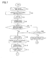
- FIG. 7 is a first main flowchart illustrating an operation of the hybrid type vehicle drive control apparatus in the first embodiment of the invention.
- FIG. 8 is a second main flowchart illustrating an operation of the hybrid type vehicle drive control apparatus in the first embodiment of the invention.
- FIG. 9 is a third main flowchart illustrating an operation of the hybrid type vehicle drive control apparatus in the first embodiment of the invention.
- FIG. 10 is a diagram indicating a first vehicle-requested torque map in the first embodiment of the invention.
- FIG. 11 is a diagram indicating a second vehicle-requested torque map in the first embodiment of the invention.
- FIG. 12 is a diagram illustrating a target engine operation state map in the first embodiment of the invention.
- FIG. 13 is a diagram indicating an engine drive region map in the first embodiment of the invention.
- FIG. 14 is a chart illustrating a sub-routine of a system voltage determination process in the first embodiment of the invention.
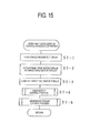
- FIG. 15 is a chart illustrating a sub-routine of a rapid acceleration control process in the first embodiment of the invention.
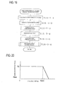
- FIG. 16 is a chart illustrating a sub-routine of a drive motor control process in the first embodiment of the invention.
- FIG. 17 is a chart illustrating a sub-routine of a generator torque control process in the first embodiment of the invention.
- FIG. 18 is a chart illustrating a sub-routine of an engine startup control process in the first embodiment of the invention.
- FIG. 19 is a chart illustrating a sub-routine of a generator rotation speed control process in the first embodiment of the invention.
- FIG. 20 is a diagram indicating a generator torque restriction map in the first embodiment of the invention.
- FIG. 21 is a chart illustrating a sub-routine of an engine stop control process in the first embodiment of the invention.
- FIG. 22 is a chart illustrating a sub-routine of a generator brake engagement control process in the first embodiment of the invention.
- FIG. 23 is a chart illustrating a sub-routine of a generator brake release control process in the first embodiment of the invention.
- FIG. 24 is a chart illustrating a sub-routine of a system voltage determination process in a second embodiment of the invention.
- FIG. 1 is a function block diagram of a hybrid type vehicle drive control apparatus in accordance with a first embodiment of the invention.
- FIG. 1 Shown in FIG. 1 are: a generator 16 for generating electric power by driving an engine that is not shown; an inverter 28 as a generator inverter for driving the generator 16; a drive motor 25 that drives a hybrid type vehicle; an inverter 29 as a drive motor inverter for driving the drive motor 25; a battery 43 connected to the inverters 28, 29; a generator inverter sensor 75 as a first voltage detection means for detecting the voltage applied to the generator inverter; a drive motor inverter sensor 76 as a second voltage detection means for detecting the voltage applied to the drive motor inverter; a battery voltage sensor 72 as a third voltage detection means for detecting the battery voltage; a system voltage determination processing means 91 for determining a system voltage based on results of detection by the generator inverter sensor 75, the drive motor inverter sensor 76 and the battery voltage sensor 72.
- FIG. 2 is a conceptual diagram of a hybrid type vehicle in accordance with the first embodiment of the invention.
- FIG. 2 Shown in FIG. 2 are: an engine (E/G) 11 disposed on a first axis; an output shaft 12 that is disposed on the first axis and that outputs rotation provided by driving the engine 11; a planetary gear unit 13 as a differential gear device that is disposed on the first axis and that changes the speed of rotation input via the output shaft 12; an output shaft 14 that is disposed on the first axis and that outputs speed-changed rotation from the planetary gear unit 13; a first counter drive gear 15 as an output gear fixed to the output shaft 14; and a generator (G) 16 that is disposed on the first axis, and is connected to the planetary gear unit 13 via a transfer shaft 17, and is mechanically connected to the engine 11 in a fashion allowing differential rotation, and that generates power through the drive of the engine 11.
- E/G engine
- the output shaft 14 has a sleeve-like shape, and is disposed surrounding the output shaft 12.
- the first counter drive gear 15 is disposed at an engine 11-side of the planetary gear unit 13.
- the planetary gear unit 13 has at least a sun gear S as a first gear element, pinions P meshing with the sun gear S, a ring gear R as a second gear element that meshes with the pinions P, and a carrier CR as a third gear element that rotatably supports the pinions P.
- the sun gear S is mechanically connected to the generator 16 via the transfer shaft 17.
- the ring gear R is mechanically connected, via the output shaft 14 and a predetermined gear train, to a drive wheel 37 and a drive motor (M) 25 as a second electric motor for driving the hybrid type vehicle which are disposed on second axes parallel to the first axis, and which are mechanically connected to the engine 11 and the generator 16 in a fashion allowing differential rotation.
- M drive motor
- the carrier CR is mechanically connected to the engine 11 via the output shaft 12.
- a one-way clutch F is disposed between the carrier CR and a case 10 of the hybrid type vehicle drive apparatus.
- the one-way clutch F becomes free when forward rotation of the engine 11 is transferred to the carrier CR.
- the one-way clutch F is locked so as to prevent transfer of the reverse rotation to the engine 11.
- the generator 16 is made up of a rotor 21 that is fixed to the transfer shaft 17 and is rotatably disposed, a stator 22 disposed around the rotor 21, and coils 23 wound on the stator 22.
- the generator 16 generates electric power from rotation transferred thereto via the transfer shaft 17.
- the coils 23 are connected to a battery that is not shown, and supply DC current to the battery.
- a generator brake B is disposed between the rotor 21 and the case 10. By engaging the generator brake B, the rotor 21 can be fixed to mechanically stop rotation of the generator 16.
- Reference numeral 26 represents an output shaft disposed on the second axis. Via the output shaft 26, rotation of the drive motor 25 is output.
- Reference numeral 27 represents a second counter drive gear as an output gear fixed to the output shaft 26.
- the drive motor 25 is made up of a rotor 40 fixed to the output shaft 26 and rotatably disposed, a stator 41 provided around the rotor 40, and coils 42 wound on the stator 41.
- the drive motor 25 generates drive motor torque TM from electric current supplied to the coils 42. Therefore, the coils 42 are connected to the battery. DC current from the battery is converted into AC current, which is supplied to the coils 42.
- a counter shaft 30 is disposed on a third axis parallel to the first and second axes.
- a first counter driven gear 31, and a second counter driven gear 32 having more teeth than the first counter driven gear 31 are fixed to the counter shaft 30.
- the first counter driven gear 31 and the first counter drive gear 15 are meshed with each other, and the second counter driven gear 32 and the second counter drive gear 27 are meshed with each other. Therefore, rotation of the first counter drive gear 15 is reversed when transferred to the first counter driven gear 31, and rotation of the second counter drive gear 27 is reversed when transferred to the second counter driven gear 32.
- a differential pinion gear 33 having fewer teeth than the first counter driven gear 31 is fixed to the counter shaft 30.
- a differential device 36 is disposed on a fourth axis parallel to the first to third axes.
- a differential ring gear 35 of the differential device 36 is meshed with the differential pinion gear 33. Therefore, rotation transferred to the differential ring gear 35 is distributed and transferred to the drive wheels 37 by the differential device 36.
- rotation produced by the engine 11 can be transferred to the first counter driven gear 31.
- rotation produced by the drive motor 25 can be transferred to the second counter driven gear 32. Therefore, by driving the engine 11 and the drive motor 25, the hybrid type vehicle can be run.
- Reference numeral 38 represents a generator rotor position sensor, such as a resolver or the like, for detecting the position of the rotor 21, that is, the generator rotor position ⁇ G.
- Reference numeral 39 represents a drive motor rotor position sensor, such as a resolver or the like, for detecting the position of the rotor 40, that is, the drive motor rotor position ⁇ M.
- the generator rotation speed NG By computing a rate of change ⁇ G of the generator rotor position ⁇ G, it is possible to compute the generator rotation speed NG.
- a rate of change ⁇ M of the drive motor rotor position ⁇ M it is possible to compute the rotation speed of the drive motor 25, that is, the drive motor rotation speed NM.
- the vehicle speed V can be computed based on the rate of change ⁇ M, and the gear ratio ⁇ V of a torque transfer system from the output shaft 26 to the drive wheels 37.
- the generator rotor position ⁇ G corresponds to the generator rotation speed NG
- the drive motor rotor position ⁇ M corresponds to the drive motor rotation speed NM.
- the generator rotor position sensor 38 to function as a generator rotation speed detection means for detecting the generator rotation speed NG
- the drive motor rotor position sensor 39 to function as a drive motor rotation speed detection means for detecting the drive motor rotation speed NM and as a vehicle speed detection means for detecting the vehicle speed V.
- FIG. 3 is a diagram illustrating the operation of the planetary gear unit in accordance with the first embodiment of the invention.
- FIG. 4 is a vehicle speed diagram for a normal run of the vehicle in accordance with the first embodiment of the invention.
- FIG. 5 is a torque diagram for a normal run in accordance with the first embodiment of the invention.
- the carrier CR is connected to the engine 11, and the sun gear S is connected to the generator 16. Furthermore, the ring gear R is connected to the drive motor 25 and the drive wheels 37 via the output shaft 14. Therefore, the rotation speed of the ring gear R, that is, the ring gear rotation speed NR, equals the rotation speed output to the output shaft 14, that is, the output shaft rotation speed.
- the rotation speed of the carrier CR equals the rotation speed of the engine 11, that is, the engine rotation speed NE.
- Equation (1) forms a rotation speed relational expression regarding the planetary gear unit 13.
- the engine, the ring gear R and the generator receive reaction forces from one another.
- the ring gear R, the carrier CR and the sun gear S are rotated in a positive direction, and the ring gear rotation speed NR, the engine rotation speed NE and the generator rotation speed NG assume positive values as indicated in FIG. 4.
- the ring gear torque TR and the generator torque TG are acquired by splitting the engine torque TE at a torque ratio that is determined by the number of teeth of the planetary gear unit 13. Therefore, in the torque diagram of FIG. 5, the engine torque TE is the sum of the ring gear torque TR and the generator torque TG.
- FIG. 6 is a conceptual diagram illustrating a hybrid type vehicle drive control apparatus in accordance with the first embodiment of the invention.
- FIG. 6 shows: a case 10; an engine 11 (E/G); a planetary gear unit 13; a generator (G) 16; a generator brake B for fixing a rotor 21 of the generator 16; a drive motor (M) 25; an inverter 28 as a generator inverter for driving the generator 16; an inverter 29 as a drive motor inverter for driving the drive motor 25; a drive wheel 37; a generator rotor position sensor 38; a drive motor rotor position sensor 39; and a battery 43.
- the inverters 28, 29 are connected to the battery 43 via a power supply switch SW. When the power supply switch SW is on, the battery 43 sends DC current to the inverters 28, 29.
- a generator inverter sensor 75 Disposed at an input side of the inverter 28 is a generator inverter sensor 75 as a first voltage detection means for detecting the DC voltage applied to the inverter 28, that is, the generator inverter voltage VG.
- a drive motor inverter sensor 76 Disposed at an input side of the inverter 29 is a drive motor inverter sensor 76 as a second voltage detection means for detecting the DC voltage applied to the inverter 29, that is, the drive motor inverter voltage VM.
- the generator inverter voltage VG and the drive motor inverter voltage VM are sent to a generator control device 47 and a drive motor control device 49, respectively.
- a smoothing capacitor C is connected between the battery 43 and the inverter 29.
- a vehicle control device 51 is a computer that is made up of a not-shown CPU, a recording device, etc., and that performs overall control of the hybrid type vehicle.
- the vehicle control device 51 includes an engine control device 46, a generator control device 47, and a drive motor control device 49.
- the engine control device 46 is made up of a not-shown CPU, a recording device, etc., and sends instruction signals regarding the degree of throttle opening ⁇ , the valve timing, etc., to the engine 11 in order to control the engine 11.
- the generator control device 47 is made up of a not-shown CPU, a recording device, etc., and sends a drive signal SG1 to the inverter 28 in order to control the generator 16.
- the drive motor control device 49 is made up of a not-shown CPU, a recording device, etc., and sends a drive signal SG2 to the inverter 29 in order to control the drive motor 25.
- the inverter 28 is driven in accordance with the drive signal SG1.
- the inverter 28 receives DC current from the battery 43, and generates phase currents, that is, currents IGU, IGV, IGW of a U-phase, a V-phase and a W-phase, and sends the currents IGU, IGV, IGW of the phases to the generator 16.
- the inverter 28 receives the currents IGU, IGV, IGW, and generates DC currents, and sends the currents to the battery 43.
- the inverter 29 is driven in accordance with the drive signal SG2.
- the inverter 29 receives DC current from the battery 43, and generates currents IMU, IMV, IMW of a U-phase, a V-phase and a W-phase, and sends the currents IMU, IMV, IMW of the phases to the drive motor 25.
- the inverter 29 receives the currents IMU, IMV, IMW, and generates DC currents, and sends the currents to the battery 43.
- a battery remaining amount detecting device 44 that detects a battery remaining amount SOC as the state of the battery 43, that is, the battery state; an engine rotation speed sensor 52 that detects the engine rotation speed NE; a shift position sensor 53 as a speed selection operating means for detecting the position of a not-shown shift lever, that is, the shift position SP; an accelerator pedal 54; an accelerator switch 55 as an accelerator operation detection means for detecting the position (amount of depression) of the accelerator pedal 54, that is, the accelerator pedal position AP; a brake pedal 61; a brake switch 62 as a brake operation detection means for detecting the position (amount of depression) of the brake pedal 61, that is, the brake pedal position BP; an engine temperature sensor 63 that detects the temperature tmE of the engine 11; a generator temperature sensor 64 that detects the temperature of the generator 16, for example, the temperature tmG of the coils 23 (FIG. 2); and a drive motor temperature sensor 65 that detects the temperature of the drive motor 25, for example
- a battery voltage sensor 72 as a third voltage detection means for detecting the battery voltage VB as the battery state.
- the battery voltage VB is sent to the generator control device 47, the drive motor control device 49 and the vehicle control device 51.
- Battery state detection means is formed by the battery remaining amount detecting device 44, the battery voltage sensor 72, a not-shown battery current sensor, a not-shown battery temperature sensor, etc.
- the battery voltage VB, the generator inverter voltage VG and the drive motor inverter voltage VM form the first to third voltage information pieces.
- the vehicle control device 51 sets the driving and stopping of the engine 11 by sending an engine control signal to the engine control device 46, and computes the generator rotation speed NG by reading the generator rotor position ⁇ G, and computes the drive motor rotation speed NM by reading the drive motor rotor position ⁇ M, and computes the engine rotation speed NE using the rotation speed relational expression, and sets in the engine control device 46 a target engine rotation speed NE* that represents a target value of the engine rotation speed NE, and sets in the generator control device 47 a target generator rotation speed NG* that represents a target value of the generator rotation speed NG, and a target generator torque TG* that represents a target value of the generator torque TG, and sets in the drive motor control device 49 a target drive motor torque TM*that represents a target value of the drive motor torque TM, and a drive motor torque corrected value ⁇ TM that represents a corrected value of the drive motor torque TM.
- a not-shown generator rotation speed computation processing means of the vehicle control device 51 reads the generator rotor position ⁇ G, and computes the generator rotation speed NG.
- a not-shown drive motor rotation speed computation processing means of the vehicle control device 51 reads the drive motor rotor position ⁇ M, and computes the drive motor rotation speed NM.
- a not-shown engine rotation speed computation processing means of the vehicle control device 51 computes the engine rotation speed NE using the rotation speed relational expression.
- the generator rotation speed computation processing means, the drive motor rotation speed computation processing means, and the engine rotation speed computation processing means function as the generator rotation speed detection means, the drive motor rotation speed detection means, and the engine rotation speed detection means for detecting the generator rotation speed NG, the drive motor rotation speed NM, and the engine rotation speed NE.
- the engine rotation speed NE is computed by the vehicle control device 51, it is also possible to read the engine rotation speed NE from the engine rotation speed sensor 52.
- the vehicle speed V is computed from the drive motor rotor position ⁇ M, it is also possible to compute the vehicle speed V from the ring gear rotation speed NR, or compute the vehicle speed V from the rotation speed of the drive wheels 37, that is, the drive wheel rotation speed.
- a ring gear rotation speed sensor, a drive wheel rotation speed sensor, etc. may be provided as vehicle speed detection means.
- FIG. 7 is a first main flowchart illustrating an operation of the hybrid type vehicle drive control apparatus in the first embodiment of the invention.
- FIG. 8 is a second main flowchart illustrating an operation of the hybrid type vehicle drive control apparatus in the first embodiment of the invention.
- FIG. 9 is a third main flowchart illustrating an operation of the hybrid type vehicle drive control apparatus in the first embodiment of the invention.
- FIG. 10 is a diagram indicating a first vehicle-requested torque map in the first embodiment of the invention.
- FIG. 11 is a diagram indicating a second vehicle-requested torque map in the first embodiment of the invention.
- FIG. 12 is a diagram illustrating a target engine operation state map in the first embodiment of the invention.
- FIG. 13 is a diagram indicating an engine drive region map in the first embodiment of the invention.
- the horizontal axis indicates the vehicle speed V
- the vertical axis indicates the vehicle-requested torque TO*.
- the horizontal axis indicates the engine rotation speed NE
- the vertical axis indicates the engine torque TE.
- the system voltage determination processing means 91 (FIG. 1) of the vehicle control device 51 performs a system voltage determining process to determine a system voltage Vsys based on the battery voltage VB, the generator inverter voltage VG and the drive motor inverter voltage VM.
- the not-shown vehicle-requested torque determination processing means of the vehicle control device 51 performs a vehicle-requested torque determining process. That is, the vehicle-requested torque determination processing means reads the accelerator pedal position AP from the accelerator switch 55, and the brake pedal position BP from the brake switch 62, and reads the drive motor rotor position ⁇ M from the drive motor rotor position sensor 39, and computes the vehicle speed V.
- the means determines a vehicle-requested torque TO* needed to run the hybrid type vehicle which is pre-set corresponding to the accelerator pedal position AP, the brake pedal position BP and the vehicle speed V, by referring to the first vehicle-requested torque map of FIG. 10 recorded in a recording device of the vehicle control device 51 if the accelerator pedal 54 is depressed, and by referring to the second vehicle-requested torque map of FIG. 11 recorded in the recording device if the brake pedal 61 is depressed.
- the vehicle control device 51 determines whether the vehicle-requested torque TO* is greater than a maximum drive motor torque TMmax that is pre-set as a rated torque of the drive motor 25. If the vehicle-requested torque TO* is greater than the maximum drive motor torque TMmax, the vehicle control device 51 determines whether the engine 11 is at a stop. If the engine 11 is at a stop, a not-shown rapid acceleration control processing means of the vehicle control device 51 performs a rapid acceleration control process, in which the means drives the drive motor 25 and the generator 16 to run the hybrid type vehicle.
- a not-shown battery charge-discharge requested output computation processing means of the vehicle control device 51 performs a battery charge-discharge requested output computing process, in which the battery remaining amount SOC is read from the battery remaining amount detecting device 44, and a battery charge-discharge requested output PB is computed from the battery remaining amount SOC.
- a not-shown target engine operation state setting processing means of the vehicle control device 51 performs a target engine operation state setting process. That is, referring to the target engine operation state map of FIG. 12 recorded in the recording device, the target engine operation state setting processing means determines points A1 to A3, Am of intersection of lines PO1 to PO3 indicating the vehicle-requested output PO with an optimal fuel economy curve L where the efficiency of the engine 11 becomes highest at each of the accelerator pedal positions AP1 to AP6, as operation points of the engine 11 indicating the target engine operation state.
- the engine torque TE1 to TE3, TEm at the operation point is determined as a target engine torque TE*.
- the engine rotation speed NE1 to NE3 at the operation point is determined as a target engine rotation speed NE*.
- the vehicle control device 51 determines whether the engine 11 is in a drive region AR1, by referring to the engine drive region map of FIG. 13 recorded in the recording device.
- AR1 represents a drive region in which the engine 11 is driven
- AR2 represents a stop region in which the driving of the engine 11 is stopped
- AR3 represents a hysteresis region.
- LE1 represents a line on which the engine 11 in a stopped state is driven
- LE2 represents a line on which the engine 11 in a driven state is stopped being driven.
- the line LE1 is shifted rightward in FIG. 13 so as to reduce the driven region AR1.
- the line LE1 is shifted leftward in FIG. 13 so as to increase the drive region AR1.
- a not-shown engine startup control processing means of the vehicle control device 51 performs an engine startup control process to start up the engine 11. If the engine 11 is driven although the engine 11 is not in the drive region AR1, a not-shown engine stop control processing means of the vehicle control device 51 performs an engine stop control process to stop the driving of the engine 11.
- a not-shown target drive motor torque determination processing means of the vehicle control device 51 performs a target drive motor torque determination process, in which the vehicle-requested torque TO* is determined as a target drive motor torque TM*, and a not-shown drive motor control processing means of the vehicle control device 51 performs a drive motor control process to perform a torque control of the drive motor 25.
- the hybrid type vehicle is run in a motor drive mode.
- a not-shown engine control processing means of the engine control device 46 performs an engine control process, in which the engine 11 is controlled by a predetermined method.
- the generator rotation speed computation processing means of the vehicle control device 51 performs the generator rotation speed computation process, in which the drive motor rotor position ⁇ M is read, and a ring gear rotation speed NR is computed based on the drive motor rotor position ⁇ M and the gear ratio ⁇ R of a portion from the output shaft 26 to the ring gear R.
- the target engine rotation speed NE* determined in the target engine operation state setting process is read, and a target generator rotation speed NG* is computed and determined from the ring gear rotation speed NR and the target engine rotation speed NE* by using the rotation speed relational expression.
- the generator rotation speed NG is low during a run of the hybrid type vehicle in a motor-engine drive mode, the electric power consumption becomes great and the electric power generating efficiency of the generator 16 becomes low, so that the fuel economy of the hybrid type vehicle correspondingly deteriorates. Therefore, the absolute value of the target generator rotation speed NG* is less than a predetermined rotation speed, the generator brake B is engaged to mechanically stop the generator 16. Thus, the fuel economy will improve.
- the vehicle control device 51 determines whether the target generator rotation speed NG* is equal to or greater than a predetermined first rotation speed Nth1 (e.g., 500 [rpm]). If the absolute value of the target generator rotation speed NG*is equal to or greater than the first rotation speed Nth1, the vehicle control device 51 determines whether the generator brake B has been released. If the generator brake B has been released, a not-shown generator rotation speed control processing means of the vehicle control device 51 performs a generator rotation speed control process to perform a torque control of the generator 16. If the generator brake B is not released, a not-shown generator brake release control processing means of the vehicle control device 51 performs a generator brake release control process so as to release the generator brake B.
- a predetermined first rotation speed Nth1 e.g. 500 [rpm]
- a target generator torque TG* is determined and, on the basis of the target generator torque TG*, a torque control of the generator 16 is performed to generate a predetermined generator torque TG, the generator torque TG is converted into the ring gear torque TR, and is output from the ring gear R since the engine torque TE, the ring gear torque TR, and the generator torque TG are affected by reaction forces from one another as mentioned above.
- the ring gear torque TR is output from the ring gear R, the generator rotation speed NG fluctuates, and the ring gear torque TR fluctuates.
- the fluctuating ring gear torque TR is transferred to the drive wheels 37, so that the running feeling of the hybrid type vehicle deteriorates. Therefore, the ring gear torque TR is computed, taking into account a torque corresponding to the inertia of the generator 16 (inertia of the rotor 21 and a not-shown rotor shaft) involved in the fluctuations of the generator rotation speed NG.
- a not-shown ring gear torque computation processing means of the vehicle control device 51 performs a ring gear torque computation process, in which the target generator torque TG* determined in the generator rotation speed control process is read, and a ring gear torque TR is computed based on the target generator torque TG*, and the ratio of the number of teeth of the ring gear R to the number of teeth of the sun gear S.
- the value assumed by the torque equivalent component TGI during acceleration of the hybrid type vehicle is negative with respect to the accelerating direction.
- the value of the torque equivalent component TGI during deceleration is positive.
- the angular acceleration ⁇ G is computed by differentiating the generator rotation speed NG.
- the ring gear torque TR can be computed from the target generator torque TG* and the torque equivalent component TGI.
- a not-shown drive shaft torque estimation processing means of the vehicle control device 51 performs a drive shaft torque estimation process, in which the torque of the output shaft 26 of the drive motor 25, that is, the drive shaft torque TR/OUT, is computed and estimated based on the target generator torque TG*, and the torque equivalent component TGI corresponding to the inertia InG of the generator 16. Therefore, the drive shaft torque estimation processing means computes the drive shaft torque TR/OUT based on the ring gear torque TR, and the ratio of the number of teeth of the second counter drive gear 27 to the number of teeth of the ring gear R.
- the drive shaft torque estimation processing means reads the engine torque TE from the engine control device 46, and computes a ring gear torque TR from the engine torque TE using the aforementioned torque relational expression, and then estimates the drive shaft torque TR/OUT based on the ring gear torque TR, and the ratio of the number of teeth of the second counter drive gear 27 to the number of teeth of the ring gear R.
- the target drive motor torque determination processing means performs a target drive motor torque determination process, in which a surplus or shortfall of the drive shaft TR/OUT is determined as a target drive motor torque TM* by subtracting the drive shaft TR/OUT from the vehicle requested torque TO*.
- a not-shown drive motor control processing means of the vehicle control device 51 performs a drive motor control process, in which a torque control of the drive motor 25 is performed based on an estimated drive shaft TR/OUT, so as to control the drive motor torque TM.
- the vehicle control device 51 determines whether the generator brake B is engaged. If the generator brake B is engaged, the vehicle control device 51 ends the process. If the generator brake B is not engaged, a not-shown generator brake engagement control processing means of the vehicle control device 51 performs a generator brake engagement control process to engage the generator brake B.
- Step S1 A system voltage determination process is performed.
- Step S2 An accelerator pedal position AP and a brake pedal position BP are read.
- Step S3 A vehicle speed V is computed.
- Step S4 A vehicle requested torque TO* is determined.
- Step S5 It is determined whether the vehicle requested torque TO* is greater than the maximum drive motor torque TMmax. If the vehicle requested torque TO* is greater than the maximum drive motor torque TMmax, the process proceeds to step S6. If the vehicle requested torque TO* is not greater than the maximum drive motor torque TMmax, the process proceeds to step S8.
- Step S6 It is determined whether the engine 11 is at a stop. If the engine 11 is at a stop, the process proceeds to step S7. If the engine 11 is not at a stop (is being driven), the process proceeds to step S8.
- Step S7 A rapid acceleration control process is performed. After that, the process ends.
- Step S8 A driver requested output PD is computed.
- Step S9 A battery charge-discharge requested output PB is computed.
- Step S10 A vehicle-requested output PO is computed.
- Step S11 An operation point of the engine 11 is determined.
- Step S12 It is determined whether the engine 11 is in the drive region AR1. If the engine 11 is in the drive region AR1, the process proceeds to step S13. If the engine 11 is not in the drive region AR1, the process proceeds to step S14.
- Step S13 It is determined whether the engine 11 is being driven. If the engine 11 is being driven, the process proceeds to step S17. If the engine 11 is not being driven, the process proceeds to step S15.
- Step S14 It is determined whether the engine 11 is being driven. If the engine 11 is being driven, the process proceeds to step S16. If the engine 11 is not being driven, the process proceeds to step S26.
- Step S15 An engine startup control process is performed. After that, the process ends.
- Step S16 An engine stop control process is performed. After that, the process ends.
- Step S17 An engine control process is performed.
- Step S18 A target generator rotation speed NG* is determined.
- Step S19 It is determined whether the absolute value of the target generator rotation speed NG* is equal to or greater than first rotation speed Nth1. If the absolute value of the target generator rotation speed NG* is equal to or greater than the first rotation speed Nth1, the process proceeds to step S20. If the absolute value of the target generator rotation speed NG* is less than the first rotation speed Nth1, the process proceeds to step S21.
- Step S20 It is determined whether the generator brake B has been released. If the generator brake B has been released, the process proceeds to step S23. If the generator brake B has not been released, the process proceeds to step S24.
- Step S21 It is determined whether the generator brake B has been engaged. If the generator brake B has been engaged, the process ends. If the generator brake B has not been engaged, the process proceeds to step S22.
- Step S22 A generator brake engagement control process is performed. After that, the process ends.
- Step S23 A generator rotation speed control process is performed.
- Step S24 A generator brake release control process is performed. After that, the process ends.
- Step S25 A drive shaft TR/OUT is estimated.
- Step S26 A target drive motor torque TM* is determined.
- Step S27 A drive motor control process is performed. After that, the process ends.
- FIG. 14 is a chart illustrating the sub-routine of the system voltage determination process in the first embodiment of the invention.
- the system voltage determination processing means 91 reads the battery voltage VB, and reads the generator inverter voltage VG via the generator control device 47, and reads the drive motor inverter voltage VM via the drive motor control device 49.
- a not-shown detection abnormality determination processing means of the system voltage determination processing means 91 performs a detection abnormality determination process, in which an abnormality determination regarding the battery voltage VB, the generator inverter voltage VG and the drive motor inverter voltage VM is performed based on a difference in voltage, that is, a differential voltage, between two of the battery voltage VB, the generator inverter voltage VG and the drive motor inverter voltage VM, which are results of detection by the battery voltage sensor 72, the generator inverter sensor 75 and the drive motor inverter sensor 76.
- the detection abnormality determination processing means determines whether the second differential voltage ⁇ Vgb is greater than the threshold value Vth2. If the second differential voltage ⁇ Vgb is greater than the threshold value Vth2, the detection abnormality determination processing means determines that the battery voltage VB is abnormal. If the second differential voltage ⁇ Vgb is less than or equal to the threshold value Vth2, the detection abnormality determination processing means determines that each of the battery voltage VB, the generator inverter voltage VG and the drive motor inverter voltage VM is normal. Although in this embodiment, the threshold values Vth1 and Vth2 are equal, the threshold values may be different from each other.
- the system voltage determination processing means 91 sets the battery voltage VB or the drive motor inverter voltage VM as a system voltage Vsys. If it is determined that the drive motor inverter voltage VM is abnormal, the system voltage determination processing means 91 sets the battery voltage VB or the generator inverter voltage VG as a system voltage Vsys. If it is determined that the battery voltage VB is abnormal, the system voltage determination processing means 91 sets the generator inverter voltage VG or the drive motor inverter voltage VM as a system voltage Vsys.
- the system voltage determination processing means 91 sets the battery voltage VB, the generator inverter voltage VG or the drive motor inverter voltage VM as a system voltage Vsys.
- Step S1-1 The battery voltage VB, the generator inverter voltage VG and the drive motor inverter voltage VM are read.
- Step S1-2 It is determined whether the first differential voltage ⁇ Vmg is greater than the threshold value Vth1. If the first differential voltage ⁇ Vmg is greater than the threshold value Vth1, the process proceeds to step S1-3. If the first differential voltage ⁇ Vmg is not greater than the threshold value Vth1, the process proceeds to step S1-4.
- Step S1-3 It is determined whether the second differential voltage ⁇ Vgb is greater than the threshold value Vth2. If the second differential voltage ⁇ Vgb is greater than the threshold value Vth2, the process proceeds to step S1-5 If the second differential voltage ⁇ Vgb is not greater than the threshold value Vth2, the process proceeds to step S1-7.
- Step S1-4 It is determined whether the second differential voltage ⁇ Vgb is greater than the threshold value Vth2. If the second differential voltage ⁇ Vgb is greater than the threshold value Vth2, the process proceeds to step S1-9. If the second differential voltage ⁇ Vgb is not greater than the threshold value Vth2, the process proceeds to step S1-11.
- Step S1-5 It is determined that the generator inverter voltage VG is abnormal.
- Step S1-6 The battery voltage VB or the drive motor inverter voltage VM is set as a system voltage Vsys. After that, the process ends.
- Step S1-7 It is determined that the drive motor inverter voltage VM is abnormal.
- Step S1-8 The battery voltage VB or the generator inverter voltage VG is set as a system voltage Vsys. After that, the process ends.
- Step S1-9 It is determined that the battery voltage VB is abnormal.
- Step S1-10 The generator inverter voltage VG or the drive motor inverter voltage VM is set as a system voltage Vsys. After that, the process ends.
- Step S1-11 The battery voltage VB, the generator inverter voltage VG or the drive motor inverter voltage VM is set as a system voltage Vsys. After that, the process ends.
- FIG. 15 is a chart illustrating the sub-routine of the rapid acceleration control process in the first embodiment of the invention.
- the rapid acceleration control processing means reads the vehicle-requested torque TO*, and sets the maximum drive motor torque TMmax as a target drive motor torque TM*. Subsequently, a target generator torque computation processing means of the rapid acceleration control processing means performs a target generator torque computation process, in which a differential torque ⁇ T between the vehicle-requested torque TO* and the target drive motor torque TM* is computed, and a shortfall of the maximum drive motor torque TMmax, which is the target drive motor torque TM*, is computed and determined as a target generator torque TG*.
- the drive motor control processing means of the rapid acceleration control processing means performs a drive motor control process, in which the torque control of the drive motor 25 (FIG. 6) is performed based on the target drive motor torque TM*.
- the generator torque control means of the rapid acceleration control processing means performs the generator torque control process, in which a torque control of the generator 16 is performed based on the generator torque TG.
- Step S7-1 The vehicle-requested torque TO* is read
- Step S7-2 The maximum drive motor torque TMmax is set as a target drive motor torque TM*.
- Step S7-3 The target generator torque TG* is computed.
- Step S7-4 The drive motor control process is performed.
- Step S7-5 The generator torque control process is performed. The process then returns.
- FIG. 16 is a chart illustrating the sub-routine of the drive motor control process in the first embodiment of the invention.
- the drive motor control processing means reads the target drive motor torque TM*, and reads the drive motor rotor position ⁇ M. From the drive motor rotor position ⁇ M, the drive motor control processing means computes a drive motor rotation speed NM. Subsequently, the means reads the system voltage Vsys. Next, the drive motor control processing means determines a d-axis current instruction value IMd* and a q-axis current instruction value IMq* based on the target drive motor torque TM*, the drive motor rotation speed NM and the system voltage Vsys, with reference to a not-shown current instruction value map for the drive motor control recorded in the recording device.
- the current IMW may also be detected by an electric current sensor, as is the case with the currents IMU, IMV.
- the drive motor control processing means performs 3-phase/2-phase conversion of converting the currents IMU, IMV, IMW into a d-axis current IMd and a q-axis current IMq. From the d-axis current IMd, the q-axis current IMq, the d-axis current instruction value IMd* and the q-axis current instruction value IMq*, the means computes voltage instruction values VMd*, VMq*. Then, the drive motor control processing means performs 2-phase/3-phase conversion of converting the voltage instruction values VMd*, VMq* into voltage instruction values VMU*, VMV*, VMW*.
- the means From the voltage instruction values VMU*, VMV*, VMW*, the means computes pulse width modulation signals SU, SV, SW. Then, the means outputs the pulse width modulation signals SU, SV, SW to a drive processing means of the drive motor control processing means.
- the drive processing means performs a drive process, and sends a drive signal SG2 to the inverter 29 based on the pulse width modulation signals SU, SV, SW.
- step S7-4 Since the same process is performed in step S7-4 and step S27, step S7-4 will be described herein.
- Step S7-4-1 The target drive motor torque TM* is read.
- Step S7-4-2 The drive motor rotor position ⁇ M is read.
- Step S7-4-3 The drive motor rotation speed NM is computed.
- Step S7-4-4 The system voltage Vsys is read.
- Step S7-4-5 The d-axis current instruction value IMd* and the q-axis current instruction value IMq* are determined.
- Step S7-4-6 The currents IMU, IMV are read.
- Step S7-4-7 The 3-phase/2-phase conversion is performed.
- Step S7-4-8 The voltage instruction values VMd*, VM* are computed.
- Step S7-4-9 The 2-phase/3-phase conversion is performed.
- Step S7-4-10 The pulse width modulation signals SU, SV, SW are output. Then, the process returns.
- FIG. 17 is a chart illustrating the sub-routine of the generator torque control process in the first embodiment of the invention.
- the generator torque control processing means reads the target generator torque TG*, and reads the generator rotor position ⁇ G. From the generator rotor position ⁇ G, the means computes a generator rotation speed NG. Subsequently, the means reads the system voltage Vsys. Next, the generator torque control processing means determines a d-axis current instruction value IGd* and a q-axis current instruction value IGq* based on the target generator torque TG*, the generator rotation speed NG and the system voltage Vsys, with reference to a not-shown current instruction value map for generator control recorded in the recording device.
- the current IGW may also be detected by an electric current sensor as in the case of the currents IGU, IGV.
- the generator torque control processing means performs 3-phase/2-phase conversion of converting the currents IGU, IGV, IGW into a d-axis current IGd and a q-axis current IGq. From the d-axis current IGd, the q-axis current IGq, the d-axis current instruction value IGd* and the q-axis current instruction value IGq*, the means computes voltage instruction values VGd*, VGq*. Then, the drive motor control processing means performs 2-phase/3-phase conversion of converting the voltage instruction values VGd*, VGq* into voltage instruction values VGU*, VGV*, VGW*.
- the means From the voltage instruction values VGU*, VGV*, VGW*, the means computes pulse width modulation signals SU, SV, SW. Then, the means outputs the pulse width modulation signals SU, SV, SW to a drive processing means of the generator torque control processing means.
- the drive processing means performs a drive process, and sends a drive signal SG1 to the inverter 28 based on the pulse width modulation signals SU, SV, SW.
- Step S7-5-1 The target generator torque TG* is read.
- Step S7-5-2 The generator rotor position ⁇ G is read.
- Step S7-5-3 The generator rotation speed NG is computed.
- Step S7-5-4 The system voltage Vsys is read.
- Step S7-5-5 The d-axis current instruction value IGd* and the q-axis current instruction value IGq* are determined.
- Step S7-5-6 The currents IGU, IGV are read.
- Step S7-5-7 The 3-phase/2-phase conversion is performed.
- Step S7-5-8 The voltage instruction values VGd*, VGq* are computed.
- Step S7-5-9 The 2-phase/3-phase conversion is performed.
- Step S7-5-10 The pulse width modulation signals SU, SV, SW are output. Then, the process returns.
- FIG. 18 is a chart illustrating the sub-routine of the engine startup control process in the first embodiment of the invention.
- the engine startup control processing means reads the degree of throttle opening ⁇ . If the degree of throttle opening ⁇ is 0 [%], the means reads the vehicle speed V, and reads the operation point of the engine 11 (FIG. 2) determined in the target engine operation state setting process.
- the vehicle speed V is computed based on the drive motor rotor position ⁇ M as mentioned above.
- the engine startup control processing means reads the drive motor rotor position ⁇ M.
- the means computes a ring gear rotation speed NR based on the drive motor rotor position ⁇ M and the gear ratio ⁇ R, and reads the target engine rotation speed NE* at the aforementioned operation point.
- the engine startup control processing means then computes and determines a target generator rotation speed NG* based on the ring gear rotation speed NR and the target engine rotation speed NE* by using the rotation speed relational expression.
- the engine startup control processing means compares the engine rotation speed NE with a pre-set startup rotation speed NEth1, and determines whether the engine rotation speed NE is higher than the startup rotation speed NEth1. If the engine rotation speed NE is higher than the startup rotation speed NEth1, the engine startup control processing means performs fuel injection and ignition in the engine 11.
- the generator rotation speed control processing means of the engine startup control processing means performs a generator rotation speed control process based on the target generator rotation speed NC*, so as to increase the generator rotation speed NG and therefore increase the engine rotation speed NE.
- the engine startup control processing means estimates a drive shaft torque TR/OUT, and determines a target drive motor torque TM*, and performs the drive motor control process, as in steps S25 to S27.
- the engine startup control processing means adjusts the degree of throttle opening ⁇ so that the engine rotation speed NE reaches the target engine rotation speed NE*.
- the engine startup control processing means determines whether the generator torque TG is smaller than a motoring torque TEth involved in the startup of the engine 11. Then, the means waits for a predetermined time to elapse with the generator torque TG remaining smaller than the motoring torque TEth.
- the generator rotation speed control processing means performs the generator rotation speed control process based on the target generator rotation speed NG*. Subsequently, the engine startup control processing means estimates a drive shaft torque TR/OUT, and determines a target drive motor torque TM*, and performs the drive motor control process as in steps S25 to S27.
- Step S15-1 It is determined whether the degree of throttle opening ⁇ is 0 [%]. If the degree of throttle opening ⁇ is 0 [%], the process proceeds to step S15-3. If the degree of throttle opening ⁇ is not 0 [%], the process proceeds to step S15-2.
- Step S15-2 The degree of throttle opening ⁇ is set to 0 [%]. Then, the process returns to Step S15-1.
- Step S15-3 The vehicle speed V is read.
- Step S15-4 The operation point of the engine 11 is read.
- Step S15-5 The target generator rotation speed NG* is determined.
- Step S15-6 It is determined whether the engine rotation speed NE is higher than the startup rotation speed NEth1. If the engine rotation speed NE is higher than the startup rotation speed NEth1, the process proceeds to step S15-11. If the engine rotation speed NE is not higher than the startup rotation speed NEth1, the process proceeds to step S15-7.
- Step S15-7 The generator rotation speed control process is performed.
- Step S15-8 The drive shaft torque TR/OUT is estimated.
- Step S15-9 The target drive motor torque TM* is determined.
- Step S15-10 The drive motor control process is performed. Then, the process returns to Step S15-1.
- Step S15-11 Fuel injection and ignition are performed.
- Step S15-12 The generator rotation speed control process is performed.
- Step S15-13 The drive shaft torque TR/OUT is estimated.
- Step S15-14 The target drive motor torque TM* is determined.
- Step S15-15 The drive motor control process is performed.
- Step S15-16 The degree of throttle opening ⁇ is adjusted.
- Step S15-17 It is determined whether the generator torque TG is smaller than the motoring torque TEth. If the generator torque TG is smaller than the motoring torque TEth, the process proceeds to step S15-18. If the generator torque TG is not smaller than the motoring torque TEth, the process returns to Step S15-11.
- Step S15-18 The elapse of a predetermined time is awaited. At the elapse, the process returns.
- FIG. 19 is a chart illustrating the sub-routine of the generator rotation speed control process in the first embodiment of the invention.
- FIG. 20 is a diagram indicating a generator torque restriction map in the first embodiment of the invention. In FIG. 20, the horizontal axis indicates the system voltage Vsys, and the vertical axis indicates the maximum generator torque TGmax.
- the generator rotation speed control processing means reads the target generator rotation speed NG* and the generator rotation speed NG.
- the means performs a PI control based on a differential rotation speed ⁇ NG between the generator rotation speed NG and the target generator rotation speed NG*, and computes a target generator torque TG*. If the differential rotation speed ⁇ NG is greater, the target generator torque TG* is increased with the positive-negative sign being considered.
- the generator torque restriction processing means of the generator rotation speed control processing means performs a generator torque restriction process, in which the system voltage Vsys is read, and the generator torque TG is restricted corresponding to the system voltage Vsys. Therefore, the generator torque restriction processing means computes the maximum generator torque TGmax of the generator torque TG corresponding to the system voltage Vsys with reference to the generator torque restriction map of FIG. 20 recorded in the recording device in the vehicle control device 51 (FIG. 6). Then, the means restricts the generator torque TG based on the maximum generator torque TGmax.
- the maximum generator torque TGmax assumes a predetermined value TG1 if the system voltage Vsys is less than or equal to a predetermined threshold value Vsys1. If the system voltage Vsys is higher than the threshold value Vsys1, the maximum generator torque TGmax is reduced with increases in the system voltage Vsys. Therefore, if the generator 16 is driven at the maximum generator torque TGmax, the target generator torque TG* is reduced as the maximum generator torque TGmax decreases.
- the generator torque restriction processing means determines the restricted generator torque TG as a target generator torque TG*.
- the generator torque control processing means of the generator rotation speed control processing means performs the generator torque control process illustrated in FIG. 17, thereby performing the torque control of the generator 16.
- the generator torque TG is restricted. Therefore, increases in the load applied to the inverter 28 can be prevented. Furthermore, with regard to the driving of the inverter 28, if the switching of a transistor of the inverter 28 is performed, and therefore, a surge voltage which is a transient voltage transiently occurs so that the system voltage Vsys becomes high, the load applied to the inverter 28 does not increase.
- Step S15-7 Since the same process is performed in Steps S15-7, S15-12 and S23, Step S15-7 will be described.
- Step S15-7-1 The target generator rotation speed NG* is read.
- Step S15-7-2 The generator rotation speed NG is read.
- Step S15-7-3 The target generator torque TG* is computed.
- Step S15-7-4 The system voltage Vsys is read.
- Step S15-7-5 The target generator torque TG* is determined.
- Step S15-7-6 The generator torque control process is performed. Then, the process returns.
- FIG. 21 is a chart illustrating the sub-routine of the engine stop control process in the first embodiment of the invention.
- the engine stop control processing means determines whether the generator brake B has been released (FIG. 6). If the generator brake B is not released, but is engaged, the generator brake release control processing means of the engine stop control processing means performs the generator brake release control process to release the generator brake B.
- the engine stop control processing means stops fuel injection and ignition in the engine 11, and sets the degree of throttle opening 0 to 0 [%].
- the engine stop control processing means reads the ring gear rotation speed NR, and determines a target generator rotation speed NG* based on the ring gear rotation speed NR and the target engine rotation speed NE* (0 [rpm]), by using the rotation speed relational expression.
- the engine stop control processing means estimates a drive shaft torque TR/OUT, and determines a target drive motor torque TM*, and performs the drive motor control process, as in steps S25 to S27.
- the engine stop control processing means determines whether the engine rotation speed NE is less than or equal to a stop rotation speed NEth2. If the engine rotation speed NE is less than or equal to the stop rotation speed NEth2, the switching for the generator 16 is stopped to shut down the generator 16.
- Step S16-1 It is determined whether the generator brake B has been released. If the generator brake B is released, the process proceeds to step S16-3. If the generator brake B is not released, the process proceeds to step S16-2.
- Step S16-2 The generator brake release control process is performed.
- Step S16-3 Fuel injection and ignition are stopped.
- Step S16-4 The degree of throttle opening ⁇ is set to 0 [%].
- Step S16-5 The target generator rotation speed NG* is determined.
- Step S16-6 The generator rotation speed control process is performed.
- Step S16-7 The drive shaft torque TR/OUT is estimated.
- Step S16-8 The target drive motor torque TM* is determined.
- Step S16-9 The drive motor control process is performed.
- Step S16-10 It is determined whether the engine rotation speed NE is less than or equal to the stop rotation speed NEth2. If the engine rotation speed NE is less than or equal to the stop rotation speed NEth2, the process proceeds to step S16-11. If the engine rotation speed NE is greater than the stop rotation speed NEth2, the process returns to step S16-5.
- Step S16-11 The switching for the generator 16 is stopped. Then, the process returns.
- FIG. 22 is a chart illustrating the sub-routine of the generator brake engagement control process in the first embodiment of the invention.
- the generator brake engagement control processing means switches a generator brake request for requesting engagement of the generator brake B (FIG. 6) from an off-status to an on-status, and sets 0 [rpm] as a target generator rotation speed NG*, and performs the generator rotation speed control process illustrated in FIG. 19.
- the generator brake engagement control processing means estimates a drive shaft torque TR/OUT, and determines a target drive motor torque TM*, and performs the drive motor control process.
- the generator brake engagement control processing means determines whether the absolute value of the generator rotation speed NG is smaller than a predetermined second rotation speed Nth2 (e.g., 100 [rpm]). If the absolute value of the generator rotation speed NG is smaller than the second rotation speed Nth2, the means switches the generator brake B from an off-state to an on-state, thereby engaging the brake. Subsequently, the generator brake engagement control processing means estimates a drive shaft torque TR/OUT, and determines a target drive motor torque TM*, and performs the drive motor control process, as in steps S25 to S27.
- a predetermined second rotation speed Nth2 e.g. 100 [rpm]
- the generator brake engagement control processing means stops the switching for the generator 16 to shut down the generator 16.
- Step S22-1 The target generator rotation speed NG* is set at 0 [rpm].
- Step S22-2 The generator rotation speed control process is performed.
- Step S22-3 The drive shaft torque TR/OUT is estimated.
- Step S22-4 The target drive motor torque TM* is determined.
- Step S22-5 The drive motor control process is performed.
- Step S22-6 It is determined whether the absolute value of the generator rotation speed NG is smaller than the second rotation speed Nth2. If the absolute value of the generator rotation speed NG is smaller than the second rotation speed Nth2, the process proceeds to step S22-7. If absolute value of the generator rotation speed NG is not smaller than the second rotation speed Nth2, the process returns to step S22-2.
- Step S22-7 The generator brake B is engaged.
- Step S22-8 The drive shaft torque TR/OUT is estimated.
- Step S22-9 The target drive motor torque TM* is determined.
- Step S22-10 The drive motor control process is performed.
- Step S22-11 It is determined whether the predetermined time has elapsed. If the predetermined has elapsed, the process proceeds to step S22-12. If the time has not elapsed, the process returns to step S22-7.
- Step S22-12 The switching for the generator 16 is stopped. Then, the process returns.
- FIG. 23 is a chart illustrating the sub-routine of the generator brake release control process in the first embodiment of the invention.
- the engine torque TE transferred to the rotor 21 is estimated or computed.
- the generator brake release control processing means reads a torque corresponding to the estimated or computed engine torque TE, that is, the engine torque-corresponding amount, and sets the engine torque-corresponding amount as a target generator torque TG*. Subsequently, the generator brake release control processing means performs the generator torque control process illustrated in FIG. 17, and then estimates a drive shaft torque TR/OUT, and determines a target drive motor torque TM*, and performs the drive motor control process as in steps S25 to S27.
- the generator brake release control processing means switches the generator brake B from the on-state to the off-state, thereby releasing the brake.
- the means After setting the target generator rotation speed NG* at 0 [rpm], the means performs the generator rotation speed control process illustrated in FIG. 19.
- the generator brake release control processing means estimates a drive shaft torque TR/OUT, and determines a target drive motor torque TM*, and performs the drive motor control process as in steps S25 to S27.
- the aforementioned engine torque-corresponding amount is estimated or computed by learning the torque ratio of the generator torque TG to the engine torque TE.
- Step S24-1 The engine torque-corresponding amount is set as a target generator torque TG*.
- Step S24-2 The generator torque control process is performed.
- Step S24-3 The drive shaft torque TR/OUT is estimated.
- Step S24-4 The target drive motor torque TM* is determined.
- Step S24-5 The drive motor control process is performed.
- Step S24-6 It is determined whether the predetermined time has elapsed. If the predetermined time has elapsed, the process proceeds to step S24-7. If the time has not elapsed, the process returns Step S24-2.
- Step S24-7 The generator brake B is released.
- Step S24-8 The target generator rotation speed NG* is set at 0 [rpm].
- Step S24-9 The generator rotation speed control process is performed.
- Step S24-10 The drive shaft torque TR/OUT is estimated.
- Step S24-11 The target drive motor torque TM* is determined.
- Step S24-12 The drive motor control process is performed. Then, the process returns.
- any one of the battery voltage sensor 72, the generator inverter sensor 75 and the drive motor inverter sensor 76 has a detection abnormality due to a broken wire, a short circuit or the like, it becomes impossible to normally detect the battery voltage VB, the generator inverter voltage VG or the drive motor inverter voltage VM, and therefore it becomes impossible to smoothly perform various drive controls such as the torque control of the generator 16, the rotation speed control of the generator 16, the torque control of the drive motor 25, etc.
- FIG. 24 is a chart illustrating a sub-routine of a system voltage determination process in the second embodiment of the invention.
- the system voltage determination processing means 91 (FIG. 1) reads the battery voltage VB, which is a result of detection by the battery voltage sensor 72 as a third voltage detection means, and reads, via the generator control device 47 (FIG. 6), the generator inverter voltage VG, which is a result of detection by the generator inverter sensor 75 as a first voltage detection means, and reads, via the drive motor control device 49, the drive motor inverter voltage VM, which is a result of detection by the drive motor inverter sensor 76 as a second voltage detection means.
- a not-shown detection abnormality determination processing means of the system voltage determination processing means 91 performs a detection abnormality determination process, in which abnormality determination regarding the battery voltage VB, the generator inverter voltage VG and the drive motor inverter voltage VM is performed based on the battery voltage VB, the generator inverter voltage VG and the drive motor inverter voltage VM. That is, the detection abnormality determination processing means determines whether first to third judgment conditions are met, based on whether the battery voltage VB is higher than a threshold value Vth11, and whether the generator inverter voltage VG is higher than the threshold value Vth11, and whether the drive motor inverter voltage VM is less than or equal to a threshold value Vth12. If the first to third judgment conditions are met, the detection abnormality determination processing means determines that the drive motor inverter sensor 76 has a broken wire.
- the detection abnormality determination processing means determines whether fourth to sixth judgment conditions are met, based on whether the battery voltage VB is less than or equal to the threshold value Vth12, and whether the generator inverter voltage VG is less than or equal to the threshold value Vth12, and whether the drive motor inverter voltage VM is higher than the threshold value Vth11.
- the detection abnormality determination processing means determines that the drive motor inverter sensor 76 has a short circuit. If at least one of the fourth to sixth judgment conditions is unmet, that is, if the battery voltage VB is higher than the threshold value Vth12 or the generator inverter voltage VG is higher than the threshold value Vth12 or the drive motor inverter voltage VM is less than or equal to the threshold value Vth11, the detection abnormality determination processing means determines that the battery voltage sensor 72, the generator inverter sensor 75 and the drive motor inverter sensor 76 are normal. Although in this embodiment, the threshold value Vth12 is set lower than the threshold value Vth11, the threshold values Vth11 and Vth12 may be equal to each other.
- the system voltage determination processing means 91 sets the battery voltage VB or the generator inverter voltage VG as a system voltage Vsys. If it is determined that the battery voltage sensor 72, the generator inverter sensor 75 and the drive motor inverter sensor 76 are all normal, the system voltage determination processing means 91 sets the battery voltage VB, the generator inverter voltage VG or the drive motor inverter voltage VM as a system voltage Vsys.
- the drive motor inverter sensor 76 in order to determine whether the drive motor inverter sensor 76 has a broken wire or has a short circuit, it is determined whether the battery voltage VB is higher than the threshold value Vth11, and whether the generator inverter voltage VG is higher than the threshold value Vth11, and whether the drive motor inverter voltage VM is less than or equal to the threshold value Vth12, and it is also determined whether the battery voltage VB is less than or equal to the threshold value Vth12, and whether the generator inverter voltage VG is less than or equal to the threshold value Vth12, and whether the drive motor inverter voltage VM is higher than the threshold value Vth11. It is also possible to determine whether the battery voltage sensor 72 and the generator inverter sensor 75 have a broken wire or a short circuit in a similar manner.
- the determination as to whether the battery voltage sensor 72 has a broken line or a short circuit it is determined whether the generator inverter voltage VG is higher than the threshold value Vth11, and the drive motor inverter voltage VM is higher than the threshold value Vth11, and whether the battery voltage VB is less than or equal to Vth12, and it is also determined whether the drive motor inverter voltage VM is less than or equal to the threshold value Vth12, and whether the generator inverter voltage VG is less than or equal to the threshold value Vth12, and the battery voltage VB is higher than the threshold value Vth11.
- the determination as to whether the generator inverter sensor 75 has a broken line or a short circuit it is determined whether the battery voltage VB is higher than the threshold value Vth11, and whether the drive motor inverter voltage VM is higher than the threshold value Vth11, and whether the generator inverter voltage VG is less than or equal to the threshold value Vth12, and it is determined whether the battery voltage VB is less than or equal to the threshold value Vth12, and whether the drive motor inverter voltage VM is less than or equal to the threshold value Vth12, and whether the generator inverter voltage VG is higher than the threshold value Vth11.
- any one of the battery voltage sensor 72, the generator inverter sensor 75 and the drive motor inverter sensor 76 has a detection abnormality due to a broken wire or a short circuit, based on the battery voltage VB, the generator inverter voltage VG and the drive motor inverter voltage VM, that is, based on a result of comparison of two of the battery voltage VB, the generator inverter voltage VG and the drive motor inverter voltage VM with a threshold value, and a result of comparison of the other one of them with a threshold.
- Step S1-11 The battery voltage VB, the generator inverter voltage VG and the drive motor inverter voltage VM are read.
- Step S1-12 It is determined whether the battery voltage VB is higher than the threshold value Vth11, and the generator inverter voltage VG is higher than the threshold value Vth11, and the drive motor inverter voltage VM is less than or equal to the threshold value Vth12.
- step S13 If the battery voltage VB is higher than the threshold value Vth11 and the generator inverter voltage VG is higher than the threshold value Vth11 and the drive motor inverter voltage VM is less than or equal to the threshold value Vth12, the process proceeds to step S13, if the battery voltage VB is less than or equal to than the threshold value Vth11, or if the generator inverter voltage VG is less than or equal to than the threshold value Vth11, or if the drive motor inverter voltage VM is higher than the threshold value Vth12, the process proceeds to step S15.
- Step S1-15 It is determined whether the battery voltage VB is less than or equal to the threshold value Vth12, and the generator inverter voltage VG is less than or equal to the threshold value Vth12, and the drive motor inverter voltage VM is higher than the Vth11. If the battery voltage VB is less than or equal to the threshold value Vth12 and the battery voltage VB is less than or equal to the threshold value Vth12 and the drive motor inverter voltage VM is higher than the threshold value Vth11, the process proceeds to step S1-16.
- step S1-18 If the battery voltage VB is higher than the threshold value Vth12, or if the generator inverter voltage VG is higher than the threshold value Vth12, or if the drive motor inverter voltage VM is less than or equal to the threshold value Vth11, the process proceeds to step S1-18.
- Step S1-16 It is determined that the drive motor inverter sensor 76 has a short circuit.
- Step S1-17 The battery voltage VB or the generator inverter voltage VG is set as a system voltage Vsys. After that, the process ends.
- Step S1-18 The battery voltage VB, the generator inverter voltage VG or the drive motor inverter voltage VM is set as a system voltage Vsys. After that, the process ends.
- the generator torque TG is restricted if the system voltage Vsys is high, it is also possible to restrict the drive motor torque TM in that case.
- the hybrid type vehicle drive control apparatus includes: an electric generator that generates an electric power by driving an engine; an electric generator inverter for driving the electric generator; a drive motor that drives a hybrid type vehicle; a drive motor inverter for driving the drive motor; a battery connected to the electric generator inverter and the drive motor inverter; first voltage detection means for detecting a voltage applied to the electric generator inverter; second voltage detection means for detecting a voltage applied to the drive motor inverter; third voltage detection means for detecting a battery voltage; and system voltage determination processing means for determining a system voltage based on detection results provided by the first to third voltage detection means.
- the apparatus if any one of the voltage information pieces from any one of the first to third voltage detection means has a detection abnormality, it is possible to determine the system voltage based on the detection results provided by the first to third voltage detection means. Therefore, the apparatus is able to smoothly perform various drive controls such as the torque control of the electric generator, the rotation speed control of the generator, the torque control of the drive motor, etc.
- the system voltage determination processing means determines the system voltage based on a difference between detection results provided by two voltage detection means of the first to third voltage detection means.
- the system voltage determination processing means determines the system voltage based on the detection result provided by each of the first to third voltage detection means.
Landscapes
- Engineering & Computer Science (AREA)
- Transportation (AREA)
- Mechanical Engineering (AREA)
- Chemical & Material Sciences (AREA)
- Combustion & Propulsion (AREA)
- Power Engineering (AREA)
- Life Sciences & Earth Sciences (AREA)
- Sustainable Development (AREA)
- Sustainable Energy (AREA)
- Automation & Control Theory (AREA)
- Electric Propulsion And Braking For Vehicles (AREA)
- Hybrid Electric Vehicles (AREA)
Applications Claiming Priority (2)
| Application Number | Priority Date | Filing Date | Title |
|---|---|---|---|
| JP2001233098A JP4158363B2 (ja) | 2001-08-01 | 2001-08-01 | ハイブリッド型車両駆動制御装置 |
| JP2001233098 | 2001-08-01 |
Publications (3)
| Publication Number | Publication Date |
|---|---|
| EP1281562A2 true EP1281562A2 (fr) | 2003-02-05 |
| EP1281562A3 EP1281562A3 (fr) | 2003-12-17 |
| EP1281562B1 EP1281562B1 (fr) | 2015-03-18 |
Family
ID=19064914
Family Applications (1)
| Application Number | Title | Priority Date | Filing Date |
|---|---|---|---|
| EP02017229.2A Expired - Lifetime EP1281562B1 (fr) | 2001-08-01 | 2002-07-31 | Dispositif et méthode de commande d'entraînement pour un véhicule du type hybride et programme correspondante |
Country Status (4)
| Country | Link |
|---|---|
| US (1) | US6757598B2 (fr) |
| EP (1) | EP1281562B1 (fr) |
| JP (1) | JP4158363B2 (fr) |
| KR (1) | KR100898915B1 (fr) |
Cited By (5)
| Publication number | Priority date | Publication date | Assignee | Title |
|---|---|---|---|---|
| EP1283122A2 (fr) | 2001-08-10 | 2003-02-12 | Aisin Aw Co., Ltd. | Dispositif et méthode de commande d'entraínement pour un véhicule du type hybride et programme correspondante |
| WO2005049366A1 (fr) * | 2003-11-19 | 2005-06-02 | Toyota Jidosha Kabushiki Kaisha | Appareil de detection d'anomalie dans un circuit de commande de charge |
| CN104029606B (zh) * | 2014-03-31 | 2016-06-22 | 北京工业大学 | 一种车用永磁同步电机增程器控制方法 |
| CN108819937A (zh) * | 2018-07-04 | 2018-11-16 | 重庆长安汽车股份有限公司 | 新能源汽车跛行模式控制方法及系统 |
| CN111409460A (zh) * | 2020-04-09 | 2020-07-14 | 浙江吉利汽车研究院有限公司 | 一种用于电动汽车的驱动电机旋转状态监控方法及系统 |
Families Citing this family (42)
| Publication number | Priority date | Publication date | Assignee | Title |
|---|---|---|---|---|
| JP3638263B2 (ja) * | 2001-09-10 | 2005-04-13 | 本田技研工業株式会社 | 車両駆動装置 |
| US20040089485A1 (en) * | 2002-11-08 | 2004-05-13 | Kramer Dennis A. | Vehicle drive arrangement having multiple-sized electric motors |
| JP3928559B2 (ja) * | 2003-01-10 | 2007-06-13 | トヨタ自動車株式会社 | 電圧変換装置、故障処理をコンピュータに実行させるプログラムを記録したコンピュータ読取り可能な記録媒体および故障処理方法 |
| DE10301531A1 (de) * | 2003-01-17 | 2004-08-05 | Daimlerchrysler Ag | Einrichtung und Verfahren zum Betrieb einer elektrischen Maschine eines Kraftfahrzeuges |
| JP3894168B2 (ja) * | 2003-07-15 | 2007-03-14 | トヨタ自動車株式会社 | 動力出力装置およびその制御方法並びに自動車 |
| KR100588500B1 (ko) * | 2003-09-24 | 2006-06-13 | 현대자동차주식회사 | 모터를 이용한 사륜구동 장치 및 그 제어방법 |
| DE10346213A1 (de) * | 2003-10-06 | 2005-04-21 | Bosch Gmbh Robert | Verfahren zur Regelung des Ladezustands eines Energiespeichers bei einem Fahrzeug mit Hybridantrieb |
| JP3991983B2 (ja) * | 2003-12-19 | 2007-10-17 | 日産自動車株式会社 | 車両の駆動制御装置 |
| JP2005304229A (ja) * | 2004-04-14 | 2005-10-27 | Nissan Motor Co Ltd | ハイブリッド車のモータフェイル対応制御装置 |
| US7378808B2 (en) * | 2004-05-25 | 2008-05-27 | Caterpillar Inc. | Electric drive system having DC bus voltage control |
| JP4217192B2 (ja) * | 2004-06-01 | 2009-01-28 | 富士重工業株式会社 | ハイブリッド車両の制御装置 |
| US7469761B2 (en) * | 2004-06-28 | 2008-12-30 | Caterpillar Inc. | Continuously variable transmission system with power boost |
| US7419021B2 (en) * | 2004-09-27 | 2008-09-02 | Oshkosh Truck Corporation | Engine and generator orientation within a hybrid vehicle |
| JP4462224B2 (ja) * | 2006-03-31 | 2010-05-12 | マツダ株式会社 | 車両のハイブリッドシステム |
| US8361000B2 (en) * | 2007-03-29 | 2013-01-29 | Sanna Gaspard | Automated infant massager |
| JP4844753B2 (ja) * | 2007-05-09 | 2011-12-28 | 株式会社デンソー | 電気自動車の制御装置 |
| JP5036416B2 (ja) * | 2007-06-15 | 2012-09-26 | トヨタ自動車株式会社 | 電源システムおよびそれを備えた車両、ならびに充放電制御方法 |
| JP4965363B2 (ja) * | 2007-07-12 | 2012-07-04 | トヨタ自動車株式会社 | 車両およびその制御方法並びに駆動装置 |
| DE102008004366A1 (de) * | 2008-01-15 | 2009-07-16 | Robert Bosch Gmbh | Triebstranganordnung eines Fahrzeugs und Verfahren zur Steuerung des Betriebes einer Triebstranganordnung eines Fahrzeugs |
| JP4453765B2 (ja) * | 2008-02-26 | 2010-04-21 | トヨタ自動車株式会社 | ハイブリッド車およびその制御方法 |
| JP5109743B2 (ja) * | 2008-03-21 | 2012-12-26 | トヨタ自動車株式会社 | 動力システムおよびその制御方法並びに車両 |
| KR100921061B1 (ko) * | 2008-03-27 | 2009-10-08 | 현대자동차주식회사 | 하이브리드 차량의 배터리 보호방법 |
| DE102008001159A1 (de) * | 2008-04-14 | 2009-10-15 | Robert Bosch Gmbh | Verfahren und Steuerungsmodul zum Steuern des Antriebsmodus eines Hybridantriebs zur Verhinderung von Ruckbewegungen |
| US20100056325A1 (en) * | 2008-08-29 | 2010-03-04 | Paccar Inc | Automatic throttle response for a hybrid vehicle |
| DE102008042783A1 (de) * | 2008-10-13 | 2010-04-15 | Robert Bosch Gmbh | Verfahren und Vorrichtung zum Betreiben einer Antriebseinheit |
| JP5170569B2 (ja) * | 2009-03-31 | 2013-03-27 | アイシン・エィ・ダブリュ株式会社 | ハイブリッド駆動装置 |
| JP5201190B2 (ja) * | 2010-10-08 | 2013-06-05 | 三菱自動車工業株式会社 | ハイブリット車のクラッチ制御装置 |
| KR101158724B1 (ko) * | 2011-12-26 | 2012-06-22 | 국방과학연구소 | 하이브리드 차량, 및 그것의 전기 안전 장치 및 제어 방법 |
| KR20140079156A (ko) * | 2012-12-18 | 2014-06-26 | 현대자동차주식회사 | 하이브리드 차량의 모터의 토크 결정 방법 및 시스템 |
| US9719477B2 (en) | 2013-12-09 | 2017-08-01 | Textron Inc. | Using a DC or AC generator as a starter with fault detection |
| US9272628B2 (en) * | 2013-12-09 | 2016-03-01 | Textron Inc. | Using AC induction motor as a generator in a utility vehicle |
| US9035481B1 (en) * | 2013-12-09 | 2015-05-19 | Textron Inc. | Using AC and DC generators with controllers as a regenerative power burn off device |
| JP6245472B2 (ja) * | 2013-12-26 | 2017-12-13 | 東海旅客鉄道株式会社 | 電気車制御装置 |
| JP6301240B2 (ja) * | 2014-02-07 | 2018-03-28 | 本田技研工業株式会社 | 車両用バッテリ充電装置 |
| CN107078537B (zh) * | 2014-11-04 | 2018-10-12 | 本田技研工业株式会社 | 充电控制装置和充电控制方法 |
| KR102510672B1 (ko) * | 2015-10-06 | 2023-03-16 | 에이치엘만도 주식회사 | 전자식 파킹 브레이크 장치의 제어 장치 및 그 제어 방법 |
| CN107813805A (zh) * | 2016-09-09 | 2018-03-20 | 比亚迪股份有限公司 | 陡坡缓降系统及其控制方法 |
| US10507718B2 (en) * | 2017-02-15 | 2019-12-17 | Ford Global Technologies, Llc | Hybrid transaxle |
| JP6772965B2 (ja) * | 2017-06-08 | 2020-10-21 | トヨタ自動車株式会社 | 車両の制御装置 |
| JP6904226B2 (ja) * | 2017-11-16 | 2021-07-14 | トヨタ自動車株式会社 | 電源制御システムおよび方法 |
| US12384226B2 (en) * | 2018-10-03 | 2025-08-12 | Carrier Corporation | Generator temperature control |
| WO2021095058A1 (fr) * | 2019-11-15 | 2021-05-20 | Hero MotoCorp Limited | Système de démarrage de véhicule électrique |
Citations (3)
| Publication number | Priority date | Publication date | Assignee | Title |
|---|---|---|---|---|
| US5713814A (en) | 1995-08-02 | 1998-02-03 | Aisin Aw Co., Ltd. | Control system for vehicular drive unit |
| US5808428A (en) | 1995-07-03 | 1998-09-15 | Honda Giken Kogyo Kabushiki Kaisha | Control system for electric vehicle |
| DE10050379A1 (de) | 1999-10-13 | 2001-05-10 | Honda Motor Co Ltd | Steuer/Regelvorrichtung für Hybridfahrzeuge |
Family Cites Families (20)
| Publication number | Priority date | Publication date | Assignee | Title |
|---|---|---|---|---|
| US4536697A (en) * | 1983-09-09 | 1985-08-20 | General Motors Corporation | Vehicle electrical energy management system |
| JPS61262006A (ja) | 1985-05-14 | 1986-11-20 | Nissan Motor Co Ltd | 車両用誘導電動機の制御装置 |
| JP3200885B2 (ja) | 1991-10-21 | 2001-08-20 | 株式会社日立製作所 | バッテリー電圧対応型電気自動車制御装置 |
| US5343970A (en) * | 1992-09-21 | 1994-09-06 | Severinsky Alex J | Hybrid electric vehicle |
| JP3094745B2 (ja) * | 1993-09-24 | 2000-10-03 | トヨタ自動車株式会社 | ハイブリッド車の発電制御装置 |
| JP3274019B2 (ja) * | 1994-04-20 | 2002-04-15 | 三菱電機株式会社 | 車両用交流発電機制御装置 |
| JPH08336205A (ja) * | 1995-04-07 | 1996-12-17 | Nippon Soken Inc | ハイブリッド車両のバッテリ充電装置 |
| US5713425A (en) * | 1996-01-16 | 1998-02-03 | Ford Global Technologies, Inc. | Parallel hybrid powertrain for an automotive vehicle |
| US5939861A (en) * | 1996-05-24 | 1999-08-17 | Hino Jidosha Kogyo Kabushiki Kaisha | Control system for on-vehicle battery |
| JP3211702B2 (ja) | 1997-02-25 | 2001-09-25 | 株式会社デンソー | ハイブリッド車制御装置 |
| US6018694A (en) | 1996-07-30 | 2000-01-25 | Denso Corporation | Controller for hybrid vehicle |
| KR100270530B1 (ko) * | 1996-08-30 | 2000-11-01 | 정몽규 | 전기 자동차 인버터 안정화와 보호회로의 시퀀서 제어장치 |
| KR19980048723A (ko) * | 1996-12-18 | 1998-09-15 | 오상수 | 하이브리드 전기자동차 |
| JP3536581B2 (ja) * | 1997-04-16 | 2004-06-14 | 日産自動車株式会社 | ハイブリッド電気自動車の発電制御装置 |
| JP3718962B2 (ja) * | 1997-06-10 | 2005-11-24 | 株式会社エクォス・リサーチ | ハイブリッド車両 |
| JP3410022B2 (ja) * | 1998-05-20 | 2003-05-26 | 本田技研工業株式会社 | ハイブリッド車両の制御装置 |
| JP3449226B2 (ja) * | 1998-07-03 | 2003-09-22 | 日産自動車株式会社 | ハイブリッド車両のバッテリー制御装置 |
| JP3566151B2 (ja) * | 1999-10-04 | 2004-09-15 | 本田技研工業株式会社 | ハイブリッド自動車のモータ制御装置 |
| JP3529680B2 (ja) * | 1999-10-13 | 2004-05-24 | 本田技研工業株式会社 | ハイブリッド車両のモータ制御装置 |
| JP2001238303A (ja) * | 2000-02-24 | 2001-08-31 | Mitsubishi Motors Corp | ハイブリッド電気自動車の回生制御装置 |
-
2001
- 2001-08-01 JP JP2001233098A patent/JP4158363B2/ja not_active Expired - Lifetime
-
2002
- 2002-07-30 US US10/207,085 patent/US6757598B2/en not_active Expired - Lifetime
- 2002-07-31 KR KR1020020045152A patent/KR100898915B1/ko not_active Expired - Lifetime
- 2002-07-31 EP EP02017229.2A patent/EP1281562B1/fr not_active Expired - Lifetime
Patent Citations (3)
| Publication number | Priority date | Publication date | Assignee | Title |
|---|---|---|---|---|
| US5808428A (en) | 1995-07-03 | 1998-09-15 | Honda Giken Kogyo Kabushiki Kaisha | Control system for electric vehicle |
| US5713814A (en) | 1995-08-02 | 1998-02-03 | Aisin Aw Co., Ltd. | Control system for vehicular drive unit |
| DE10050379A1 (de) | 1999-10-13 | 2001-05-10 | Honda Motor Co Ltd | Steuer/Regelvorrichtung für Hybridfahrzeuge |
Cited By (7)
| Publication number | Priority date | Publication date | Assignee | Title |
|---|---|---|---|---|
| EP1283122A2 (fr) | 2001-08-10 | 2003-02-12 | Aisin Aw Co., Ltd. | Dispositif et méthode de commande d'entraínement pour un véhicule du type hybride et programme correspondante |
| WO2005049366A1 (fr) * | 2003-11-19 | 2005-06-02 | Toyota Jidosha Kabushiki Kaisha | Appareil de detection d'anomalie dans un circuit de commande de charge |
| US7432719B2 (en) | 2003-11-19 | 2008-10-07 | Toyota Jidosha Kabushiki Kaisha | Abnormality monitoring apparatus in load drive circuit |
| CN104029606B (zh) * | 2014-03-31 | 2016-06-22 | 北京工业大学 | 一种车用永磁同步电机增程器控制方法 |
| CN108819937A (zh) * | 2018-07-04 | 2018-11-16 | 重庆长安汽车股份有限公司 | 新能源汽车跛行模式控制方法及系统 |
| CN111409460A (zh) * | 2020-04-09 | 2020-07-14 | 浙江吉利汽车研究院有限公司 | 一种用于电动汽车的驱动电机旋转状态监控方法及系统 |
| CN111409460B (zh) * | 2020-04-09 | 2021-10-15 | 浙江吉利汽车研究院有限公司 | 一种用于电动汽车的驱动电机旋转状态监控方法及系统 |
Also Published As
| Publication number | Publication date |
|---|---|
| EP1281562B1 (fr) | 2015-03-18 |
| US6757598B2 (en) | 2004-06-29 |
| KR100898915B1 (ko) | 2009-05-21 |
| JP4158363B2 (ja) | 2008-10-01 |
| US20030033060A1 (en) | 2003-02-13 |
| JP2003047107A (ja) | 2003-02-14 |
| EP1281562A3 (fr) | 2003-12-17 |
| KR20030011714A (ko) | 2003-02-11 |
Similar Documents
| Publication | Publication Date | Title |
|---|---|---|
| EP1281562B1 (fr) | Dispositif et méthode de commande d'entraînement pour un véhicule du type hybride et programme correspondante | |
| US6902018B2 (en) | Electric vehicle drive control apparatus, electric vehicle drive control method, and program thereof | |
| JP3956796B2 (ja) | ハイブリッド型車両駆動制御装置、ハイブリッド型車両駆動制御方法及びそのプログラム | |
| JP4424428B2 (ja) | 電動機駆動制御装置、それを備えた車両および電動機駆動制御方法 | |
| US7999499B2 (en) | Rotating electrical machine control system and vehicle drive system | |
| JP4453765B2 (ja) | ハイブリッド車およびその制御方法 | |
| JP4236084B2 (ja) | ハイブリッド型車両駆動制御装置、ハイブリッド型車両駆動制御方法及びハイブリッド型車両駆動制御のプログラム | |
| US7353094B2 (en) | Electrically operated vehicle driving controller, electrically operated vehicle driving control method and its program | |
| EP1391342A1 (fr) | Mecanisme d'entrainement pour vehicule hybride, procede de commande et programme de mecanisme d'entrainement pour vehicule hybride | |
| US20050070397A1 (en) | Electrically operated vehicle drive controller, electrically operated vehicle drive control method, and electrically operated vehicle with a vehicle drive controller | |
| US20170129478A1 (en) | Hybrid vehicle | |
| JP2010012827A (ja) | 車両およびその制御方法 | |
| JP2009184500A (ja) | 車両およびその制御方法 | |
| JP2009227080A (ja) | 動力出力装置やこれを備える車両および駆動装置並びにこれらの制御方法 | |
| JP3873698B2 (ja) | ハイブリッド型車両駆動制御装置、ハイブリッド型車両駆動制御方法及びそのプログラム | |
| JP2007137373A (ja) | 動力出力装置およびこれを搭載する車両並びに動力出力装置の制御方法 | |
| US10745000B2 (en) | Hybrid vehicle and control method therefor | |
| JP5018548B2 (ja) | ハイブリッド車およびその制御方法 | |
| JP2007116773A (ja) | 駆動装置およびこれを搭載する車両並びに駆動装置の制御方法 | |
| JP4123728B2 (ja) | ハイブリッド型車両及びその制御方法 | |
| JP2012130098A (ja) | 電動車両 | |
| JP3988459B2 (ja) | ハイブリッド型車両駆動制御装置、ハイブリッド型車両駆動制御方法及びそのプログラム | |
| JP4010123B2 (ja) | ハイブリッド型車両駆動装置及びその制御方法 | |
| JP2003061206A (ja) | ハイブリッド型車両駆動制御装置、ハイブリッド型車両駆動制御方法及びそのプログラム | |
| JP3804667B2 (ja) | 電動車両駆動制御装置及び電動車両駆動制御方法 |
Legal Events
| Date | Code | Title | Description |
|---|---|---|---|
| PUAI | Public reference made under article 153(3) epc to a published international application that has entered the european phase |
Free format text: ORIGINAL CODE: 0009012 |
|
| AK | Designated contracting states |
Designated state(s): AT BE BG CH CY CZ DE DK EE ES FI FR GB GR IE IT LI LU MC NL PT SE SK TR |
|
| AX | Request for extension of the european patent |
Extension state: AL LT LV MK RO SI |
|
| PUAL | Search report despatched |
Free format text: ORIGINAL CODE: 0009013 |
|
| AK | Designated contracting states |
Kind code of ref document: A3 Designated state(s): AT BE BG CH CY CZ DE DK EE ES FI FR GB GR IE IT LI LU MC NL PT SE SK TR |
|
| AX | Request for extension of the european patent |
Extension state: AL LT LV MK RO SI |
|
| 17P | Request for examination filed |
Effective date: 20040514 |
|
| AKX | Designation fees paid |
Designated state(s): DE FR GB IT |
|
| 17Q | First examination report despatched |
Effective date: 20100706 |
|
| REG | Reference to a national code |
Ref country code: DE Ref legal event code: R079 Ref document number: 60247036 Country of ref document: DE Free format text: PREVIOUS MAIN CLASS: B60L0003000000 Ipc: B60K0006365000 |
|
| GRAP | Despatch of communication of intention to grant a patent |
Free format text: ORIGINAL CODE: EPIDOSNIGR1 |
|
| RIC1 | Information provided on ipc code assigned before grant |
Ipc: B60K 6/365 20071001AFI20140908BHEP Ipc: B60L 11/18 20060101ALI20140908BHEP Ipc: B60L 3/00 20060101ALI20140908BHEP |
|
| INTG | Intention to grant announced |
Effective date: 20141006 |
|
| GRAS | Grant fee paid |
Free format text: ORIGINAL CODE: EPIDOSNIGR3 |
|
| GRAA | (expected) grant |
Free format text: ORIGINAL CODE: 0009210 |
|
| AK | Designated contracting states |
Kind code of ref document: B1 Designated state(s): DE FR GB IT |
|
| REG | Reference to a national code |
Ref country code: GB Ref legal event code: FG4D |
|
| REG | Reference to a national code |
Ref country code: DE Ref legal event code: R096 Ref document number: 60247036 Country of ref document: DE Effective date: 20150430 |
|
| REG | Reference to a national code |
Ref country code: DE Ref legal event code: R097 Ref document number: 60247036 Country of ref document: DE |
|
| PG25 | Lapsed in a contracting state [announced via postgrant information from national office to epo] |
Ref country code: IT Free format text: LAPSE BECAUSE OF FAILURE TO SUBMIT A TRANSLATION OF THE DESCRIPTION OR TO PAY THE FEE WITHIN THE PRESCRIBED TIME-LIMIT Effective date: 20150318 |
|
| PLBE | No opposition filed within time limit |
Free format text: ORIGINAL CODE: 0009261 |
|
| STAA | Information on the status of an ep patent application or granted ep patent |
Free format text: STATUS: NO OPPOSITION FILED WITHIN TIME LIMIT |
|
| 26N | No opposition filed |
Effective date: 20151221 |
|
| GBPC | Gb: european patent ceased through non-payment of renewal fee |
Effective date: 20150731 |
|
| PG25 | Lapsed in a contracting state [announced via postgrant information from national office to epo] |
Ref country code: GB Free format text: LAPSE BECAUSE OF NON-PAYMENT OF DUE FEES Effective date: 20150731 |
|
| REG | Reference to a national code |
Ref country code: FR Ref legal event code: ST Effective date: 20160331 |
|
| PG25 | Lapsed in a contracting state [announced via postgrant information from national office to epo] |
Ref country code: FR Free format text: LAPSE BECAUSE OF NON-PAYMENT OF DUE FEES Effective date: 20150731 |
|
| PGFP | Annual fee paid to national office [announced via postgrant information from national office to epo] |
Ref country code: DE Payment date: 20210630 Year of fee payment: 20 |
|
| REG | Reference to a national code |
Ref country code: DE Ref legal event code: R071 Ref document number: 60247036 Country of ref document: DE |