EP1281608A2 - Durch Tretbewegung angetriebenes Fahrzeug - Google Patents
Durch Tretbewegung angetriebenes Fahrzeug Download PDFInfo
- Publication number
- EP1281608A2 EP1281608A2 EP02016709A EP02016709A EP1281608A2 EP 1281608 A2 EP1281608 A2 EP 1281608A2 EP 02016709 A EP02016709 A EP 02016709A EP 02016709 A EP02016709 A EP 02016709A EP 1281608 A2 EP1281608 A2 EP 1281608A2
- Authority
- EP
- European Patent Office
- Prior art keywords
- vehicle according
- pedal
- vehicle
- lever
- wheel
- Prior art date
- Legal status (The legal status is an assumption and is not a legal conclusion. Google has not performed a legal analysis and makes no representation as to the accuracy of the status listed.)
- Withdrawn
Links
Images
Classifications
-
- B—PERFORMING OPERATIONS; TRANSPORTING
- B62—LAND VEHICLES FOR TRAVELLING OTHERWISE THAN ON RAILS
- B62M—RIDER PROPULSION OF WHEELED VEHICLES OR SLEDGES; POWERED PROPULSION OF SLEDGES OR SINGLE-TRACK CYCLES; TRANSMISSIONS SPECIALLY ADAPTED FOR SUCH VEHICLES
- B62M1/00—Rider propulsion of wheeled vehicles
- B62M1/24—Rider propulsion of wheeled vehicles with reciprocating levers, e.g. foot levers
- B62M1/28—Rider propulsion of wheeled vehicles with reciprocating levers, e.g. foot levers characterised by the use of flexible drive members, e.g. chains
-
- B—PERFORMING OPERATIONS; TRANSPORTING
- B62—LAND VEHICLES FOR TRAVELLING OTHERWISE THAN ON RAILS
- B62K—CYCLES; CYCLE FRAMES; CYCLE STEERING DEVICES; RIDER-OPERATED TERMINAL CONTROLS SPECIALLY ADAPTED FOR CYCLES; CYCLE AXLE SUSPENSIONS; CYCLE SIDECARS, FORECARS, OR THE LIKE
- B62K3/00—Bicycles
- B62K3/002—Bicycles without a seat, i.e. the rider operating the vehicle in a standing position, e.g. non-motorized scooters; non-motorized scooters with skis or runners
Definitions
- the invention relates to a vehicle driven by pedaling with a frame and at least two wheels, one of which is steerable and one of which is driven by a wheel Pedal drive is driven, the pivoting movement in a rotary movement of the driven wheel is implemented.
- a pedal vehicle of the type known at the outset is known for which is mounted on a base for the driver, a two-armed rocker arm, the Lever arms are pressed down alternately by the driver.
- the pedal car is over a drive cable connected to the ends of the lever arms, which with the hub of the driven wheel located freewheel is connected, driven.
- a rocker roller with pedal drive which is provided with a rocker which is mounted on one side by means of a swivel joint on the base.
- the disadvantage of this drive is that a very high effort is required by the leg muscles to move the pedal car.
- DE-OS-196 02 343 are already other pedal vehicles of the type known at the outset known in which the driver on a two-armed rocker formed as a standing surface stands, which is stored in the front area on the lower horizontal frame part and in rear area through a gearbox with the driven rear wheel through a Traction device is connected and the pedal car drives in which the driver is Body weight alternately, shifted from back to front.
- the disadvantage of this drive is that the body weight of the rider standing on the pedal car, by the Weight shift from back to front, cannot be used continuously.
- Another disadvantage is seen in the fact that the type of power transmission, the body weight of the driver is not used sufficiently.
- DE 198 52 153 A1 discloses another pedal car of the type known at the outset, where the driver standing on two seesaws by alternately kicking the seesaws Chain drive drives and this then drives the rear wheel by higher gear ratio.
- the disadvantage of this drive is that the chain gear always rotates and there this chain gear is under the rockers, the whole pedal car builds up too high. Thereby Balance problems can occur because the rockers over the axis of rotation of the front and Lying on the rear wheel.
- Another disadvantage is the lack of a seat, which the driver Possibility to rest on descents.
- the present invention has for its object a pedaling movement propelled vehicle of the type mentioned in the introduction to make it easy is to be operated and the body weight of the driver standing on the vehicle, in full Scope and continuous use. In addition, a high driving speed and Traffic safety can be achieved.
- This object is achieved in that the power transmission through alternately stepping on and off the pedal, from the pedal to the bike, or the Wheels, using bicycle chains over pulley blocks.
- the invention provides that the Pedal drives consist of a long and a short lever arm, the long one Lever arm is used as a pedal lever and footprint for one foot each.
- the driven wheel is provided with two freewheels, one on the left and right, which are operated by the left or right pedal drive.
- Another embodiment of the invention provides that all wheel diameters, such as in bicycle manufacturing, can use and thus the manufacturing costs are very low can hold.
- the frame with the front fork must be adapted to the respective wheel diameters become.
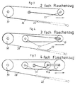
- a further embodiment of the invention provides that depending on the wheel diameter, Double, triple or quadruple pulley principle is used. With a small one Wheel diameter four times, with a medium wheel diameter three times and a double pulley principle is used for large wheel diameters.
- Another preferred embodiment of the invention provides that the on the hub of the driven wheel fixed freewheels (right and left) also with derailleur can be provided. Which is an advantage when driving uphill.
- the traverse which is fork-shaped is made, encloses the rear wheel in part, so that the axes of rotation for the pedal levers right and left can be shifted quite far to the rear to a greater length of the To reach the pedal lever so that the rider, even when he is sitting on the saddle can bring significantly greater torque to the driven wheel than the normal Bicycle.
- Another embodiment of the invention provides that the tension spring, which the chain and the pedal lever is returned to its original position, fastened in a light tube and thus the tension spring and chain not only protect against sagging, but also against Dirt and dust.
- Another preferred embodiment of the invention provides a light chain guard on the left as well as on the right side in the rear drive area over the short one Mount levers to avoid the risk of accidents.
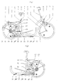
- the vehicle shown in Fig. 1 driven by pedaling consists essentially of a vehicle frame 4, which essentially consists of the frame parts traverse 25 with axis of rotation right 18, axis of rotation left 34, the rear triangle in which the driven wheel 1 is fastened, the control head 11, in which the fork is mounted with the handlebar 10 and serves to receive the steerable front wheel 9, and a pedal drive 19 on the right on its short lever arm, a deflection pinion 17 and the end of the chain 26 are fastened.
- the second deflection pinion 17 is fixedly connected to the right rear triangle of the frame with a tab.
- the drive chain 26 is pulled by means of the tension spring 22 via a freewheel with step pinion 30 and derailleur 29 into the protective tube 27, and thus forms a triple pulley according to FIG. 4, in which the load roller (deflection pinion 17) is attached to the short lever 16.
- the load roller deflection pinion 17
- the second deflection pinion 33 is fixedly connected to the left rear frame of the frame with a tab.
- the drive chain 26 is pulled into the protective tube 40 by means of the tension spring 38 via a freewheel with step pinion 43 and derailleur gear 41 and thus forms a triple block and tackle according to FIG.
Landscapes
- Engineering & Computer Science (AREA)
- Mechanical Engineering (AREA)
- Chemical & Material Sciences (AREA)
- Combustion & Propulsion (AREA)
- Transportation (AREA)
- Automatic Cycles, And Cycles In General (AREA)
- Transmission Devices (AREA)
- Motorcycle And Bicycle Frame (AREA)
Abstract
Description
Der Nachteil dieses Antriebs liegt darin, daß zum Fortbewegen des Tretmobils ein sehr hoher Kraftaufwand durch die Beinmuskeln erforderlich ist.
Das zweite Umlenkritzel 17 ist mit einer Lasche fest mit dem rechten Hinterbau des Rahmens verbunden. Die Antriebskette 26 wird mittels der Zugfeder 22 über einen Freilauf mit Stufenritzel 30 und Kettenschaltung 29 in das Schutzrohr 27 gezogen, und bildet somit nach Fig.4 einen dreifach Flaschenzug, bei dem die Lastrolle (Umlenkritzel 17) am kurzen Hebel 16 befestigt ist.
So wie einem Tretantrieb 37 links an dessen kurzem Hebelarm ein Umlenkritzel 33 und das Ende der Kette 26 befestigt ist.
Das zweite Umlenkritzel 33 ist mit einer Lasche fest mit dem linken Hinterbau des Rahmens verbunden. Die Antriebskette 26 wird mittels der Zugfeder 38 über einen Freilauf mit Stufenritzel 43 und Kettenschaltung 41 in das Schutzrohr 40 gezogen und bildet somit nach Fig.4 einen dreifach Flaschenzug, bei dem die Lastrolle (Umlenkritzel 33) am kurzen Hebel 42 befestigt ist.
Die Traverse 25, die als Support für die Drehachsen 18 und 34 gilt, ist so gefertigt, dass sie mit ihrer Gabel im hinteren Bereich das angetriebene Rad 1 noch um einen Teil umschließt. Dadurch ist es möglich die Drehachsen 18 und 34 so weit nach hinten zu legen, dass die Trethebel ihre größt mögliche Länge erhalten.
Die oberen Anschläge 24 und 39 sind so beschaffen, dass sie nach oben und unten verstellt werden können, um einen größeren oder kleineren Hub der Trethebel 19 und 37 zu ermöglichen. Die Schutzrohre 27 und 40 sind so an der Kettenschaltung befestigt, dass die Ketten 26 frei und ohne Widerstand von den Rückzugfedern 22und 38 in die Schutzrohre 21 und 40 zurückgezogen werden können. Dadurch, dass die Kettenschaltungen 29 und 41 unabhängig mit ihren Flaschenzugantrieben und Trethebeln 19 und 37 sind, ist es möglich, die verschiedenen Gangarten auf jeder Seite unterschiedlich und separat zu wählen. Die Nabe des Hinterrades weist auf der linken Seite ein Linksgewinde und auf der rechten Seite ein Rechtsgewinde zur Aufnahme der Stufenritzel und deren Freiläufe 30 und 43 auf. Dies ist erforderlich, da die Freiläufe in Antriebsrichtung blockieren und sich durch den Antrieb nicht lösen dürfen. Beim freien Rollen des Fahrzeuges oder beim Rückzug der Ketten 26 sind die Freiläufe frei und ohne Drehwiderstand. Je nach Bedarf können auch Freiläufe mit Einzelritzeln verwendet werden.
- 1
- Hinterrad
- 2
- Schutzblech
- 3
- Gepäckträger
- 4
- Fahrzeugrahmen
- 5
- Sattel
- 6
- Sattelstange höhenverstellbar
- 7
- Feststellschraube
- 8
- Vorderradschutzblech
- 9
- Vorderrad
- 10
- Lenker und Vorderradgabel
- 11
- Steuerkopf mit Lagerung
- 12
- Lampe
- 13
- Felgenbremse vorne
- 14
- Dynamo
- 15
- Seitenschutz rechts
- 16
- Kurzer Hebel mit Lasche zur Befestigung der Kette und Umlenkritzel rechts
- 17
- Umlenkritzel des rechten Flaschenzuges
- 18
- Drehachse rechts
- 19
- Trethebel rechts
- 20
- Unterer Anschlag für Trethebel rechts
- 21
- Drehpunkt und Aufhängung für Schutzrohr rechts
- 22
- Rückzugfeder rechts
- 23
- Felgenbremse hinten
- 24
- Oberer Anschlag für Trethebel rechts verstellbar
- 25
- Traverse zur Aufnahme der Drehachse 18 rechts und der Drehachse 34 links
- 26
- Fahrradkette
- 27
- Schutzrohr rechts
- 28
- Reflektoren
- 29
- Kettenschaltung rechts
- 30
- Stufenritzel mit Freilauf
- 31
- Rückstrahler
- 32
- Seitenschutz links
- 33
- Umlenkritzel des linken Flaschenzuges
- 34
- Drehachse links
- 35
- Unterer Anschlag für Trethebel links
- 36
- Drehpunkt und Aufhängung für Schutzrohr links
- 37
- Trethebel links
- 38
- Rückzugfeder links
- 39
- Oberer Anschlag für Trethebel links verstellbar
- 40
- Schutzrohr links
- 41
- Kettenschaltung links
- 42
- Kurzer Hebel mit Lasche zur Befestigung der Kette und Umlenkritzel links
- 43
- Stufenritzel mit Freilauf
Claims (15)
- Fahrzeug, insbesondere Fahrrad (Fig.1u.2) mit mindestens zwei Rädern und zwei nebeneinander parallel zum Fahrgestell liegenden Trethebeln, dadurch gekennzeichnet, dass die Kraftübertragung durch abwechselndes Auf- und Niedertreten der Trethebel, von den Trethebeln zum Rad oder den Rädern mittels Fahrradketten, über Flaschenzüge erfolgt.
- Fahrzeug nach Anspruch 1 dadurch gekennzeichnet, dass die beiden Trethebel (19 u. 37 )zum Antreiben des Fahrzeuges (Fig. 1 u. 2 ) voneinander unabhängig niedergetreten werden können.
- Fahrzeug nach Anspruch 1 und 2 dadurch gekennzeichnet, dass die Trethebel (19 u. 37 ) jeweils von den Drehachsen (18 u. 34) aus gesehen, aus jeweils einem langen Trethebel (19 u. 37 ) und einem kürzeren Hebel (16 u. 42) bestehen.
- Fahrzeug nach Anspruch 1-3 dadurch gekennzeichnet, dass der jeweilig mit dem angetriebenen Rad (1) verbundene Hebelarm (16 u. 42) kürzer ist als der jeweilige andere Trethebel (19 u. 37).
- Fahrzeug nach Anspruch 1-4 dadurch gekennzeichnet, dass die auf den jeweils langen Trethebel (19 u. 37) einwirkende Kraft auf die jeweils kurzen Hebelarme (16 u. 42) übertragen wird, wobei die einwirkende Kraft auf diese verstärkt wird.
- Fahrzeug nach Anspruch 1-5 dadurch gekennzeichnet, dass die Trethebel (19 u. 37) jeweils die Standfläche für je einen Fuß aufweisen.
- Fahrzeug nach Anspruch 1-6 dadurch gekennzeichnet, dass die Übersetzung mittels eines umgekehrten Flaschenzugprinzips vorgenommen wird.
- Fahrzeug nach Anspruch 1-7 dadurch gekennzeichnet, dass nicht nur Einzelritzel-Freiläufe links und rechts auf dem angetriebenen Rad verwendet werden, sondern auch solche, mit Kettenschaltung (30 u. 43).
- Fahrzeug nach Anspruch 1-8 dadurch gekennzeichnet, dass unterschiedliche Fahrzeugrahmengrößen 4 und unterschiedliche Raddurchmesser (1 u. 9) verwendet werden.
- Fahrzeug nach Anspruch 1-9 dadurch gekennzeichnet, dass je nach Raddurchmesser auch ein unterschiedliches Flaschenzugprinzip (Fig. 3-5) verwendet wird.
- Fahrzeug nach Anspruch 1-10 dadurch gekennzeichnet, dass die Antriebsketten 26 jeweils mittels einer Zugfeder (22 u. 38) in die Schutzrohre (27 u. 40) gezogen wird und gleichzeitig die Trethebel (19 u. 37) in ihre Ausgangslage zurückgebracht werden.
- Fahrzeug nach Anspruch 1-11 dadurch gekennzeichnet, dass die Schutzrohre (27 u. 40) bei Verwendung von Kettenschaltungen (30 u. 43) mit diesen an einem Ende verbunden sind und über die Drehpunkte (21 u. 36) frei mitschwingen können.
- Fahrzeug nach Anspruch 1-12 dadurch gekennzeichnet, dass die Trethebel (19u.37) nach unten die Anschläge (20 u. 35) haben, wobei die oberen Anschläge (24 u. 39) verstellbar sind.
- Fahrzeug nach Anspruch 1-13 dadurch gekennzeichnet, dass über den kurzen Hebelarmen (16 u.42) und deren Flaschenzügen (Fig. 3-5) am Fahrzeugrahmenhinterbau jeweils ein Schutz (15 u. 32) angebracht ist, um Unfallgefahren auszuschließen.
- Fahrzeug nach Anspruch 1-14 dadurch gekennzeichnet, dass das Fahrzeug einen Sattel (5) besitzt, so dass der Fahrer sich bei Talfahrten ausruhen kann.
Applications Claiming Priority (4)
| Application Number | Priority Date | Filing Date | Title |
|---|---|---|---|
| DE20113082U DE20113082U1 (de) | 2001-08-01 | 2001-08-01 | Durch Tretbewegung angetriebenes Fahrzeug |
| DE20113082U | 2001-08-01 | ||
| DE10138666 | 2001-08-01 | ||
| DE2001138666 DE10138666A1 (de) | 2001-08-01 | 2001-08-01 | Durch Tretbewegung angetriebenes Fahrzeug |
Publications (2)
| Publication Number | Publication Date |
|---|---|
| EP1281608A2 true EP1281608A2 (de) | 2003-02-05 |
| EP1281608A3 EP1281608A3 (de) | 2004-08-04 |
Family
ID=26009892
Family Applications (1)
| Application Number | Title | Priority Date | Filing Date |
|---|---|---|---|
| EP02016709A Withdrawn EP1281608A3 (de) | 2001-08-01 | 2002-07-26 | Durch Tretbewegung angetriebenes Fahrzeug |
Country Status (1)
| Country | Link |
|---|---|
| EP (1) | EP1281608A3 (de) |
Cited By (3)
| Publication number | Priority date | Publication date | Assignee | Title |
|---|---|---|---|---|
| WO2008063499A1 (en) * | 2006-11-21 | 2008-05-29 | Bryan Pate | Self-propelled vehicle propelled by an elliptical drive train |
| WO2009065057A3 (en) * | 2007-11-15 | 2009-07-23 | Fallbrook Technologies Inc | Continuously variable drivetrain |
| DE102021003363A1 (de) | 2021-06-25 | 2022-12-29 | Oguzhan Albayrak | Antriebsvorrichtung |
Citations (3)
| Publication number | Priority date | Publication date | Assignee | Title |
|---|---|---|---|---|
| DE4343723A1 (de) | 1992-12-23 | 1994-06-30 | Guenter Roock | Tretmobil mit wenigstens zwei Rädern |
| DE19602343A1 (de) | 1996-01-24 | 1997-07-31 | Peter Wiesner | Tretmobil |
| DE19852153A1 (de) | 1998-11-12 | 2000-05-18 | Peter Wiesner | Tretmobil |
Family Cites Families (3)
| Publication number | Priority date | Publication date | Assignee | Title |
|---|---|---|---|---|
| FR2203470A5 (de) * | 1972-10-12 | 1974-05-10 | Beauchet Jean | |
| US4445701A (en) * | 1981-12-14 | 1984-05-01 | Stroudex Industries Inc. | Vehicle structure |
| US5335927A (en) * | 1993-05-10 | 1994-08-09 | Islas John J | Pedaled propulsion system |
-
2002
- 2002-07-26 EP EP02016709A patent/EP1281608A3/de not_active Withdrawn
Patent Citations (3)
| Publication number | Priority date | Publication date | Assignee | Title |
|---|---|---|---|---|
| DE4343723A1 (de) | 1992-12-23 | 1994-06-30 | Guenter Roock | Tretmobil mit wenigstens zwei Rädern |
| DE19602343A1 (de) | 1996-01-24 | 1997-07-31 | Peter Wiesner | Tretmobil |
| DE19852153A1 (de) | 1998-11-12 | 2000-05-18 | Peter Wiesner | Tretmobil |
Cited By (3)
| Publication number | Priority date | Publication date | Assignee | Title |
|---|---|---|---|---|
| WO2008063499A1 (en) * | 2006-11-21 | 2008-05-29 | Bryan Pate | Self-propelled vehicle propelled by an elliptical drive train |
| WO2009065057A3 (en) * | 2007-11-15 | 2009-07-23 | Fallbrook Technologies Inc | Continuously variable drivetrain |
| DE102021003363A1 (de) | 2021-06-25 | 2022-12-29 | Oguzhan Albayrak | Antriebsvorrichtung |
Also Published As
| Publication number | Publication date |
|---|---|
| EP1281608A3 (de) | 2004-08-04 |
Similar Documents
| Publication | Publication Date | Title |
|---|---|---|
| EP0000553B1 (de) | Fahrradähnliches Zweiradfahrzeug | |
| EP2086824B1 (de) | Fahrzeug mit drei rädern | |
| EP2768722B1 (de) | Kompaktes, zusammenklappbares fahrrad | |
| DE69610054T2 (de) | Fahrrad mit zusätzlichem armantrieb | |
| DD293086A5 (de) | Stabilisierungsvorrichtung fuer ein einspuriges fahrzeug | |
| DE69720711T2 (de) | Fahrrad mit zweiradantrieb | |
| DE19632519B4 (de) | Fahrrad mit Hand- und Fußkurbelantrieb und Bruststütze | |
| DE4001728A1 (de) | Federungs- und antriebs-system fuer muskelgetriebene fahrzeuge | |
| EP1281608A2 (de) | Durch Tretbewegung angetriebenes Fahrzeug | |
| DE4342679A1 (de) | Tretkurbelantrieb mit einem Drehwinkel von 360 Grad sowie periodisch veränderlichen Hebelarmlängen für durch Muskelkraft angetriebene Fahrräder und Fahrzeuge | |
| DE19852153A1 (de) | Tretmobil | |
| DE19934817B4 (de) | Ruderrad, bei dem durch Anziehen und Strecken von Armen und Beinen die Fortbewegung ermöglicht wird | |
| DE102012010358A1 (de) | Fahrrad mit Arm- und oder Beinantrieb und oder mit elektrischem Antriebsmotor. | |
| DE2112645A1 (de) | Mit Muskelkraft anzutreibendes Fahrzeug | |
| DE20113082U1 (de) | Durch Tretbewegung angetriebenes Fahrzeug | |
| DE10138666A1 (de) | Durch Tretbewegung angetriebenes Fahrzeug | |
| DE69205433T2 (de) | Stabilisierungsvorrichtung für fahrzeuge. | |
| EP1982908A1 (de) | Fahrrad mit Arm- und Beinantrieb | |
| DE3332475C2 (de) | ||
| EP2790997B1 (de) | Roller mit handantrieb | |
| DE9204069U1 (de) | Vierrädriges, pedalgetriebens Fahrzeug | |
| DE2932041A1 (de) | Fahrradaehnliches zweiradfahrzeug | |
| EP0644109B1 (de) | Trethebelgetriebenes Fahrzeug | |
| DE19801461C2 (de) | Dreiradfahrzeug | |
| DE3149184A1 (de) | Fahrzeug mit fussantrieb |
Legal Events
| Date | Code | Title | Description |
|---|---|---|---|
| PUAI | Public reference made under article 153(3) epc to a published international application that has entered the european phase |
Free format text: ORIGINAL CODE: 0009012 |
|
| AK | Designated contracting states |
Designated state(s): AT BE BG CH CY CZ DE DK EE ES FI FR GB GR IE IT LI LU MC NL PT SE SK TR |
|
| AX | Request for extension of the european patent |
Extension state: AL LT LV MK RO SI |
|
| PUAL | Search report despatched |
Free format text: ORIGINAL CODE: 0009013 |
|
| AK | Designated contracting states |
Kind code of ref document: A3 Designated state(s): AT BE BG CH CY CZ DE DK EE ES FI FR GB GR IE IT LI LU MC NL PT SE SK TR |
|
| AX | Request for extension of the european patent |
Extension state: AL LT LV MK RO SI |
|
| AKX | Designation fees paid |
Designated state(s): AT BE BG CH CY CZ DE DK EE ES FI FR GB GR IE IT LI LU MC NL PT SE SK TR |
|
| STAA | Information on the status of an ep patent application or granted ep patent |
Free format text: STATUS: THE APPLICATION IS DEEMED TO BE WITHDRAWN |
|
| 18D | Application deemed to be withdrawn |
Effective date: 20050203 |