EP1281796A1 - Elément guide-fils - Google Patents
Elément guide-fils Download PDFInfo
- Publication number
- EP1281796A1 EP1281796A1 EP02405545A EP02405545A EP1281796A1 EP 1281796 A1 EP1281796 A1 EP 1281796A1 EP 02405545 A EP02405545 A EP 02405545A EP 02405545 A EP02405545 A EP 02405545A EP 1281796 A1 EP1281796 A1 EP 1281796A1
- Authority
- EP
- European Patent Office
- Prior art keywords
- thread
- shed
- lubricants
- thread guide
- coating
- Prior art date
- Legal status (The legal status is an assumption and is not a legal conclusion. Google has not performed a legal analysis and makes no representation as to the accuracy of the status listed.)
- Withdrawn
Links
- 238000009941 weaving Methods 0.000 claims abstract description 25
- 238000000576 coating method Methods 0.000 claims abstract description 22
- 238000000034 method Methods 0.000 claims abstract description 22
- 239000011248 coating agent Substances 0.000 claims abstract description 20
- 239000000314 lubricant Substances 0.000 claims abstract description 19
- 239000011159 matrix material Substances 0.000 claims abstract description 7
- 230000008569 process Effects 0.000 claims description 13
- 239000000919 ceramic Substances 0.000 claims description 9
- 239000002184 metal Substances 0.000 claims description 7
- 229910052751 metal Inorganic materials 0.000 claims description 7
- 239000004033 plastic Substances 0.000 claims description 5
- 229920003023 plastic Polymers 0.000 claims description 5
- 239000004696 Poly ether ether ketone Substances 0.000 claims description 4
- 239000004952 Polyamide Substances 0.000 claims description 4
- 238000000151 deposition Methods 0.000 claims description 4
- 230000008021 deposition Effects 0.000 claims description 4
- 229920002647 polyamide Polymers 0.000 claims description 4
- 229920002530 polyetherether ketone Polymers 0.000 claims description 4
- 238000004544 sputter deposition Methods 0.000 claims description 4
- GWEVSGVZZGPLCZ-UHFFFAOYSA-N Titan oxide Chemical compound O=[Ti]=O GWEVSGVZZGPLCZ-UHFFFAOYSA-N 0.000 claims description 3
- 238000010521 absorption reaction Methods 0.000 claims description 3
- OGIDPMRJRNCKJF-UHFFFAOYSA-N titanium oxide Inorganic materials [Ti]=O OGIDPMRJRNCKJF-UHFFFAOYSA-N 0.000 claims description 3
- 239000002131 composite material Substances 0.000 claims description 2
- 239000003795 chemical substances by application Substances 0.000 abstract 1
- 239000002344 surface layer Substances 0.000 description 12
- 239000010410 layer Substances 0.000 description 11
- 239000000463 material Substances 0.000 description 11
- 230000000694 effects Effects 0.000 description 7
- 239000011521 glass Substances 0.000 description 5
- 230000003993 interaction Effects 0.000 description 5
- 238000004519 manufacturing process Methods 0.000 description 5
- RTAQQCXQSZGOHL-UHFFFAOYSA-N Titanium Chemical compound [Ti] RTAQQCXQSZGOHL-UHFFFAOYSA-N 0.000 description 4
- 239000010408 film Substances 0.000 description 4
- 238000003780 insertion Methods 0.000 description 4
- 230000037431 insertion Effects 0.000 description 4
- 239000004753 textile Substances 0.000 description 4
- 239000010936 titanium Substances 0.000 description 4
- 229910052719 titanium Inorganic materials 0.000 description 4
- 229920000742 Cotton Polymers 0.000 description 3
- QVGXLLKOCUKJST-UHFFFAOYSA-N atomic oxygen Chemical compound [O] QVGXLLKOCUKJST-UHFFFAOYSA-N 0.000 description 3
- 229910010293 ceramic material Inorganic materials 0.000 description 3
- 230000007423 decrease Effects 0.000 description 3
- 230000007246 mechanism Effects 0.000 description 3
- 239000001301 oxygen Substances 0.000 description 3
- 229910052760 oxygen Inorganic materials 0.000 description 3
- 238000004513 sizing Methods 0.000 description 3
- 238000012549 training Methods 0.000 description 3
- IJGRMHOSHXDMSA-UHFFFAOYSA-N Atomic nitrogen Chemical compound N#N IJGRMHOSHXDMSA-UHFFFAOYSA-N 0.000 description 2
- 239000010953 base metal Substances 0.000 description 2
- 238000005256 carbonitriding Methods 0.000 description 2
- 239000004744 fabric Substances 0.000 description 2
- 238000005259 measurement Methods 0.000 description 2
- 239000000203 mixture Substances 0.000 description 2
- SOQBVABWOPYFQZ-UHFFFAOYSA-N oxygen(2-);titanium(4+) Chemical class [O-2].[O-2].[Ti+4] SOQBVABWOPYFQZ-UHFFFAOYSA-N 0.000 description 2
- 229920000728 polyester Polymers 0.000 description 2
- 238000012545 processing Methods 0.000 description 2
- 238000003860 storage Methods 0.000 description 2
- 239000000758 substrate Substances 0.000 description 2
- OKTJSMMVPCPJKN-UHFFFAOYSA-N Carbon Chemical compound [C] OKTJSMMVPCPJKN-UHFFFAOYSA-N 0.000 description 1
- 229920000914 Metallic fiber Polymers 0.000 description 1
- 239000004677 Nylon Substances 0.000 description 1
- 229920002292 Nylon 6 Polymers 0.000 description 1
- 229910002065 alloy metal Inorganic materials 0.000 description 1
- 238000005275 alloying Methods 0.000 description 1
- 230000015572 biosynthetic process Effects 0.000 description 1
- 229910052799 carbon Inorganic materials 0.000 description 1
- 229920002678 cellulose Polymers 0.000 description 1
- 239000001913 cellulose Substances 0.000 description 1
- 238000001311 chemical methods and process Methods 0.000 description 1
- 238000006243 chemical reaction Methods 0.000 description 1
- 239000007795 chemical reaction product Substances 0.000 description 1
- 210000001520 comb Anatomy 0.000 description 1
- 230000007797 corrosion Effects 0.000 description 1
- 238000005260 corrosion Methods 0.000 description 1
- 230000001419 dependent effect Effects 0.000 description 1
- 238000011161 development Methods 0.000 description 1
- 238000010894 electron beam technology Methods 0.000 description 1
- 239000007789 gas Substances 0.000 description 1
- 230000020169 heat generation Effects 0.000 description 1
- 238000007654 immersion Methods 0.000 description 1
- 230000001050 lubricating effect Effects 0.000 description 1
- 238000005461 lubrication Methods 0.000 description 1
- 238000010297 mechanical methods and process Methods 0.000 description 1
- 150000002739 metals Chemical class 0.000 description 1
- 238000010327 methods by industry Methods 0.000 description 1
- 229910052757 nitrogen Inorganic materials 0.000 description 1
- 229920001778 nylon Polymers 0.000 description 1
- 238000007750 plasma spraying Methods 0.000 description 1
- 230000002028 premature Effects 0.000 description 1
- 230000035484 reaction time Effects 0.000 description 1
- 230000009467 reduction Effects 0.000 description 1
- 238000005201 scrubbing Methods 0.000 description 1
- 239000000126 substance Substances 0.000 description 1
- 238000004381 surface treatment Methods 0.000 description 1
- 229920002994 synthetic fiber Polymers 0.000 description 1
- 230000002123 temporal effect Effects 0.000 description 1
- 238000007751 thermal spraying Methods 0.000 description 1
- 239000010409 thin film Substances 0.000 description 1
- 230000036962 time dependent Effects 0.000 description 1
- 210000002268 wool Anatomy 0.000 description 1
Images
Classifications
-
- D—TEXTILES; PAPER
- D03—WEAVING
- D03D—WOVEN FABRICS; METHODS OF WEAVING; LOOMS
- D03D41/00—Looms not otherwise provided for, e.g. for weaving chenille yarn; Details peculiar to these looms
- D03D41/005—Linear-shed multiphase looms
-
- B—PERFORMING OPERATIONS; TRANSPORTING
- B65—CONVEYING; PACKING; STORING; HANDLING THIN OR FILAMENTARY MATERIAL
- B65H—HANDLING THIN OR FILAMENTARY MATERIAL, e.g. SHEETS, WEBS, CABLES
- B65H57/00—Guides for filamentary materials; Supports therefor
- B65H57/24—Guides for filamentary materials; Supports therefor with wear-resistant surfaces
-
- D—TEXTILES; PAPER
- D01—NATURAL OR MAN-MADE THREADS OR FIBRES; SPINNING
- D01H—SPINNING OR TWISTING
- D01H13/00—Other common constructional features, details or accessories
- D01H13/04—Guides for slivers, rovings, or yarns; Smoothing dies
-
- D—TEXTILES; PAPER
- D01—NATURAL OR MAN-MADE THREADS OR FIBRES; SPINNING
- D01H—SPINNING OR TWISTING
- D01H13/00—Other common constructional features, details or accessories
- D01H13/30—Moistening, sizing, oiling, waxing, colouring, or drying yarns or the like as incidental measures during spinning or twisting
-
- B—PERFORMING OPERATIONS; TRANSPORTING
- B65—CONVEYING; PACKING; STORING; HANDLING THIN OR FILAMENTARY MATERIAL
- B65H—HANDLING THIN OR FILAMENTARY MATERIAL, e.g. SHEETS, WEBS, CABLES
- B65H2701/00—Handled material; Storage means
- B65H2701/30—Handled filamentary material
- B65H2701/31—Textiles threads or artificial strands of filaments
Definitions
- the invention relates to a thread guide element and a method for Coating a surface of a thread guide according to the General term of the independent claim of the respective category.
- Thread guide elements Numerous components in textile machines that are in contact with threads, that are carried out at high speed are special loads exposed by frictional forces.
- Components of textile machinery in contact with guided threads stand and / or are intended to guide threads as Thread guide elements called.
- the term includes the following Fadens in addition to textile threads, consisting of different fabrics, such as for example wool, cotton or silk, also yarns or threads like e.g. Paper yarn, cellulose yarn or synthetic yarn made of Perlon, nylon, Dralon or other synthetic materials, as well as threads in the broadest sense, i.e. for example, wires made of glass, metal or other materials.
- Particularly large frictional forces occur in places where the Thread pressed onto the corresponding thread guide element with great force becomes.
- Thread guide elements which are entirely are made of ceramic materials.
- the disadvantage of such Thread guiding elements consists on the one hand in that in the manufacturing process considerable effort must be made to precisely meet the required adhering to geometrical error tolerances, on the other hand, show ceramics basically significantly worse than with metals Thermal conductivity properties, so that the frictional heat generated during operation only insufficiently dissipated.
- thread guide elements are also known which are made entirely of metal are made.
- the surfaces of such thread guide elements are then common hardened with special processes to wear the relatively soft Reduce metal body in operation.
- the precise is true to size Manufacturing such thread guide elements technically and economically guaranteed, however, the susceptibility to wear is in comparison with that from ceramic materials manufactured thread guide elements despite hardened Surfaces still significantly higher.
- hardened surfaces usually have a high resistance compared to the investment and / or storage of third-party components demonstrate. This means in particular that carried along by the thread or on lubricants and / or lubricants supplied in other ways are either at all not or only insufficiently on and / or in the surface of the Can attach thread guide.
- the object of the invention is therefore to provide an improved thread guide develop that the frictional forces between guided thread and Thread guiding element reduced to a minimum, thereby reducing the friction Wear of the thread guiding element is substantially prevented and thus the Lifespan is increased massively and moreover economically and can be made to size with the highest precision.
- the thread guide element according to the invention for guiding threads is thereby characterized in that a surface of the body of the thread guide at least in the area in which the thread is guided, with a Surface coating is provided, which is designed as a matrix Has structure for receiving lubricants and / or lubricants.
- Such a thin film of lubricants and / or lubricants between Thread and surface coating of the thread guide element leads to the fact that the friction between thread and thread guide element to a considerable extent is reduced.
- both the mechanical wear of Thread, thread guide element and system or contacting them Machine components reduced in operation, as well as the production of Frictional heat further reduced.
- the life of the thread guide and the system or machine components in contact with it is significantly increased and the tissue quality is significantly improved.
- the inevitable residual heat due to an incomplete vanishing friction coefficient for the friction between thread and Thread guiding element is due to the good thermal conductivity of the Thread guide element according to the invention reliably discharged.
- the inventive method for coating a Thread guide element produced on the surface of the body of the Thread guide element at least in the area in which the thread is guided becomes a surface coating that has a structure formed as a matrix for receiving lubricants and / or lubricants.
- the surfaces of thread guide elements can be in different ways are treated and are often wholly or partly with Surface layers, consisting of various materials, Mistake. These surface layers are preferably used in Range of chemically, thermally or mechanically stressed Make the workpiece and usually have the job of Susceptibility to wear due to mechanical loads or corrosion reduce and thus increase the life of the workpiece.
- the problem is the dimensional accuracy of the treated workpiece very often a central point as to the possible uses of different Coating techniques restricted or in the special case entirely can ban.
- the thickness of the layers applied is not uncommon due to the process outside tolerable tolerances, so that coated workpiece mechanically or chemically in complex processes must be reworked.
- the coating of metallic workpieces or workpieces made of plastic are suitable for the case that the dimensional accuracy of the workpiece with high precision must be guaranteed to process the workpiece itself during the Only slightly stress the coating process and moreover very thin surface layers with thicknesses in the range of a few Generate micrometers.
- a thread guide for guiding of threads in which a surface of the body of the Thread guide element at least in the area in which the thread is guided is provided with a surface coating one as a matrix trained structure for the absorption of lubricants and / or lubricants has a compartment holding element is described in the following, as in Row shed weaving machines is used, as well as a suitable one Process for producing a thin ceramic Surface coating specified.
- a thread guide can also in other forms, e.g. as a ring, eyelet, roll, comb, groove or on one other way to be carried out concretely.
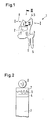
- Fig. 1 shows a schematic representation of an inventive Shed holding element 1 for a row shed weaving machine.
- the one made of metal Manufactured body 3 of the compartment holding element 1 is completely or partially with a Ceramic surface layer 5 and is by the pin 6 in Web rotor anchored.
- the warp thread 8 is used for shed formation during operation the compartment holding element 1 perpendicular to the section line II - II along the direction I - I passed over the coated surface of the compartment holding element 1.
- the weft thread is guided through the weft insertion channel 2 perpendicular to the plane spanned by the section line II-II and the direction I-I .
- Fig. 2 shows the same compartment holding element 1 in section along the section line II - II, additional layers and a warp thread 8 are shown.
- Row shed weaving machines are multi-phase weaving machines, in which several weft threads shifted against each other in stages in rotating Weaving fans are entered, the weaving chain using a weaving rotor is performed, the continuous rotation of which is an essential component representing specialist training.
- the complete specialist training is done through the interaction of several functional elements.
- Compartment holding elements 1 the compartments arranged one behind the other. In doing so the warp threads 8 are positioned by a suitable device so that they when lifting by a compartment holding element 1 either form the high compartment or remain in the low position.
- this includes autismhaltelement 1 a body 3, which is delimited by an edge layer 4. It is known that the edge layers 4 of the compartment holding elements carbonitride to achieve a hardening of the surfaces and thus the Reduce wear from friction. A major disadvantage of the However, carbonitriding consists in the fact that the surface layers are treated in this way 4 generally a high resistance to deposition and / or Show storage of substances on and / or in the surface.
- Compartment holding element 1 with integrated weft insertion channel 2 consists of a body 3 made of metal, the one Has edge layer 4, which is made of the same material as the body 3 itself exists and at least one additional ceramic surface layer 5.
- the edge layer 4 of the metallic body 3 of the compartment holding element 1 is carbonitrided. Carbonitriding is a special type of Surface treatment of a metallic thread guide. there in a thermochemical process, the surface layers of the Thread guiding element enriched with carbon and nitrogen. On the Carbonitrided edge layer 4 of the compartment holding element 1 becomes a maximum layer 5, ten micrometers thick, consisting of a ceramic material applied by deposition from the gas phase.
- Titanium oxide is used for the coating material.
- the special advantages of sputtering over others Coating methods include the low one Deposition temperature and in the possibility of uniform thin Produce layers with controlled stoichiometry in the micrometer range can. Time-consuming reworking of the layers by mechanical or chemical process is not necessary.
- the points in the process of Sputtering applied ceramic surface formed as a matrix Structure that is suitable for the absorption of lubricants and / or lubricants is; so that the lubricants and / or lubricants in this matrix-like trained structure of the coated surface and / or can be stored.
- the warp thread 8 When processing the warp thread 8 in textile machines, the warp thread 8 generally not processed dry, but for various reasons impregnated with a mixture of different components, which besides other properties also certain lubrication and / or sliding properties having.
- the mixture of different components is usually referred to as sizing.
- the size is in the processing process from Warp thread 8 carried and can be at the points of contact between Warp thread 8 and compartment holding element 1 on the sputtered surface 5 of the Attach compartment holding element 1. It is not necessary that the thread carries the size to the compartment holding element 1. Rather, the size can also through special, possibly additional, devices on the surface of the compartment holding element 1 are applied.
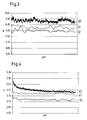
- the measured coefficient of friction ⁇ show Values in the order of ⁇ ⁇ 0.20 - 0.30 and are characterized by strong fluctuations in the value of the coefficient of friction ⁇ depending from time. These fluctuations in the coefficient of friction ⁇ lead to corresponding fluctuations in the mechanical tension in the warp thread 8.
- 4 shows the results of analog measurements of the Friction coefficient ⁇ for glass 40, cotton 41 and polyester 42, which at Use of the inventive, coated with titanium oxide Compartmental element 1 were achieved. After a short time the falls The coefficient of friction ⁇ massively decreases to values in all threads examined are more than 30% lower than the uncoated Specialist elements, which on the training of the thin mentioned Sizing film 7 on the ceramic surface layer 5 of the Compartment holding element 1 is attributable (see Fig. 4).
Landscapes
- Engineering & Computer Science (AREA)
- Textile Engineering (AREA)
- Mechanical Engineering (AREA)
- Looms (AREA)
Priority Applications (1)
| Application Number | Priority Date | Filing Date | Title |
|---|---|---|---|
| EP02405545A EP1281796A1 (fr) | 2001-07-26 | 2002-06-28 | Elément guide-fils |
Applications Claiming Priority (3)
| Application Number | Priority Date | Filing Date | Title |
|---|---|---|---|
| EP01810738 | 2001-07-26 | ||
| EP01810738 | 2001-07-26 | ||
| EP02405545A EP1281796A1 (fr) | 2001-07-26 | 2002-06-28 | Elément guide-fils |
Publications (1)
| Publication Number | Publication Date |
|---|---|
| EP1281796A1 true EP1281796A1 (fr) | 2003-02-05 |
Family
ID=26077408
Family Applications (1)
| Application Number | Title | Priority Date | Filing Date |
|---|---|---|---|
| EP02405545A Withdrawn EP1281796A1 (fr) | 2001-07-26 | 2002-06-28 | Elément guide-fils |
Country Status (1)
| Country | Link |
|---|---|
| EP (1) | EP1281796A1 (fr) |
Cited By (1)
| Publication number | Priority date | Publication date | Assignee | Title |
|---|---|---|---|---|
| DE10331503A1 (de) * | 2003-07-10 | 2005-02-10 | Maschinenfabrik Rieter Ag | Fadenleitelement zum Führen von Fäden |
Citations (5)
| Publication number | Priority date | Publication date | Assignee | Title |
|---|---|---|---|---|
| US3370410A (en) * | 1965-01-29 | 1968-02-27 | Caron Spinning Company | Spinning device |
| US4525417A (en) * | 1982-02-27 | 1985-06-25 | U.S. Philips Corporation | Carbon-containing sliding layer |
| US4655259A (en) * | 1985-04-02 | 1987-04-07 | Sulzer Brothers Limited | Lamella for a picking comb of a weaving rotor |
| DE3703078A1 (de) * | 1986-02-08 | 1987-08-20 | Barmag Barmer Maschf | Fadenfuehrer mit verschleissarmer oberflaechenbeschichtung |
| CH681150A5 (en) * | 1990-06-28 | 1993-01-29 | Rieter Ag Maschf | Yarn deflection guide with thermal control - has separate adjustments made to set yarn temp. at the deflection point |
-
2002
- 2002-06-28 EP EP02405545A patent/EP1281796A1/fr not_active Withdrawn
Patent Citations (5)
| Publication number | Priority date | Publication date | Assignee | Title |
|---|---|---|---|---|
| US3370410A (en) * | 1965-01-29 | 1968-02-27 | Caron Spinning Company | Spinning device |
| US4525417A (en) * | 1982-02-27 | 1985-06-25 | U.S. Philips Corporation | Carbon-containing sliding layer |
| US4655259A (en) * | 1985-04-02 | 1987-04-07 | Sulzer Brothers Limited | Lamella for a picking comb of a weaving rotor |
| DE3703078A1 (de) * | 1986-02-08 | 1987-08-20 | Barmag Barmer Maschf | Fadenfuehrer mit verschleissarmer oberflaechenbeschichtung |
| CH681150A5 (en) * | 1990-06-28 | 1993-01-29 | Rieter Ag Maschf | Yarn deflection guide with thermal control - has separate adjustments made to set yarn temp. at the deflection point |
Cited By (1)
| Publication number | Priority date | Publication date | Assignee | Title |
|---|---|---|---|---|
| DE10331503A1 (de) * | 2003-07-10 | 2005-02-10 | Maschinenfabrik Rieter Ag | Fadenleitelement zum Führen von Fäden |
Similar Documents
| Publication | Publication Date | Title |
|---|---|---|
| DE2206698C3 (de) | Bauteil zur Führung von Textilfaden oder-bahnen | |
| DE2926080A1 (de) | Mittel zur trockenschmierung | |
| DE19522934A1 (de) | Kugelumlaufspindel | |
| DE4115616C2 (de) | Hartstoff-Mehrlagenschichtsystem für Werkzeuge | |
| EP0201602B1 (fr) | Anneau pour machines a filer | |
| DE19630149C2 (de) | Gleitbauteil und dessen Verwendung als Kolbenring | |
| EP0631961B1 (fr) | Elément de guidage de fils textiles à surface améliorée | |
| DE3043959A1 (de) | Verfahren und vorrichtung zur herstellung eines drahts aus stahl zur verstaerkung von gegenstaenden aus kautschuk, insbesondere luftreifen | |
| EP0599286B1 (fr) | Elément de guidage de fils textiles avec une surface améliorée et procédé de fabrication d'un tel élément | |
| EP1281796A1 (fr) | Elément guide-fils | |
| DE112022006616T5 (de) | Wolframdraht und metallnetz | |
| CH671034A5 (fr) | ||
| DE19612225A1 (de) | Einsatz von Niederdruck-Plasmen zur Erzeugung elektrisch leitfähiger, textiler Fäden | |
| DE19947547A1 (de) | Spinnrotor für eine Offenend-Spinnmaschine | |
| DE102007018476A1 (de) | Walze für Papiermaschine | |
| EP0725159B1 (fr) | Procédé de revêtement | |
| EP3112531B1 (fr) | Composant pour une machine destinee a fabriquer et/ou a traiter une bande de matiere fibreuse et utilisation d'une poudre à pulvériser pour produire une couche fonctionelle pour un composant pour une machine destinee a fabriquer et/ou a traiter une bande de matiere fibreuse | |
| EP4112958A1 (fr) | Composant palier | |
| DE10249905A1 (de) | Garniturring für eine Auflösewalze einer Offenend-Spinnvorrichtung | |
| EP0020399B1 (fr) | Anneau de filage en acier pour metiers a anneau et continus a retordre a anneau | |
| DE102004029659B4 (de) | Auflöseeinrichtung für Spinnmaschinen | |
| DE3806770A1 (de) | Verfahren und vorrichtung zum verbessern der hafteigenschaften einer kunststoffoberflaeche | |
| DE102010035584A1 (de) | Bauteil zur Führung eines synthetischen Fadens | |
| EP1496004A1 (fr) | Elément de guidage pour filières | |
| DE102021000118B3 (de) | Siebgewebe mit erhöhter Verschleißfestigkeit und Verfahren zur Erhöhung der Verschleißfestigkeit eines Siebgewebes |
Legal Events
| Date | Code | Title | Description |
|---|---|---|---|
| PUAI | Public reference made under article 153(3) epc to a published international application that has entered the european phase |
Free format text: ORIGINAL CODE: 0009012 |
|
| AK | Designated contracting states |
Designated state(s): AT BE CH CY DE DK ES FI FR GB GR IE IT LI LU MC NL PT SE TR |
|
| AX | Request for extension of the european patent |
Extension state: AL LT LV MK RO SI |
|
| 17P | Request for examination filed |
Effective date: 20030708 |
|
| AKX | Designation fees paid |
Designated state(s): BE DE IT |
|
| STAA | Information on the status of an ep patent application or granted ep patent |
Free format text: STATUS: THE APPLICATION HAS BEEN WITHDRAWN |
|
| 18W | Application withdrawn |
Effective date: 20040209 |