EP1281809A2 - Bande pour presse à patin - Google Patents
Bande pour presse à patin Download PDFInfo
- Publication number
- EP1281809A2 EP1281809A2 EP02255326A EP02255326A EP1281809A2 EP 1281809 A2 EP1281809 A2 EP 1281809A2 EP 02255326 A EP02255326 A EP 02255326A EP 02255326 A EP02255326 A EP 02255326A EP 1281809 A2 EP1281809 A2 EP 1281809A2
- Authority
- EP
- European Patent Office
- Prior art keywords
- belt
- nip
- shoe
- press
- elastic material
- Prior art date
- Legal status (The legal status is an assumption and is not a legal conclusion. Google has not performed a legal analysis and makes no representation as to the accuracy of the status listed.)
- Granted
Links
- 239000013013 elastic material Substances 0.000 claims description 34
- 238000010008 shearing Methods 0.000 abstract description 10
- 238000005336 cracking Methods 0.000 abstract 1
- 235000019589 hardness Nutrition 0.000 description 26
- 230000000694 effects Effects 0.000 description 6
- 239000004744 fabric Substances 0.000 description 6
- 239000000463 material Substances 0.000 description 6
- 238000002474 experimental method Methods 0.000 description 4
- 239000000945 filler Substances 0.000 description 4
- 230000002411 adverse Effects 0.000 description 3
- 229920001971 elastomer Polymers 0.000 description 2
- 238000000034 method Methods 0.000 description 2
- 239000003094 microcapsule Substances 0.000 description 2
- XLYOFNOQVPJJNP-UHFFFAOYSA-N water Substances O XLYOFNOQVPJJNP-UHFFFAOYSA-N 0.000 description 2
- 239000000806 elastomer Substances 0.000 description 1
- 239000004088 foaming agent Substances 0.000 description 1
- 230000007774 longterm Effects 0.000 description 1
- 229920005749 polyurethane resin Polymers 0.000 description 1
- 229920005989 resin Polymers 0.000 description 1
- 239000011347 resin Substances 0.000 description 1
- 230000007704 transition Effects 0.000 description 1
- 239000011800 void material Substances 0.000 description 1
- 239000002759 woven fabric Substances 0.000 description 1
Images



Classifications
-
- D—TEXTILES; PAPER
- D21—PAPER-MAKING; PRODUCTION OF CELLULOSE
- D21F—PAPER-MAKING MACHINES; METHODS OF PRODUCING PAPER THEREON
- D21F3/00—Press section of machines for making continuous webs of paper
- D21F3/02—Wet presses
-
- D—TEXTILES; PAPER
- D21—PAPER-MAKING; PRODUCTION OF CELLULOSE
- D21F—PAPER-MAKING MACHINES; METHODS OF PRODUCING PAPER THEREON
- D21F3/00—Press section of machines for making continuous webs of paper
- D21F3/02—Wet presses
- D21F3/0209—Wet presses with extended press nip
- D21F3/0218—Shoe presses
- D21F3/0227—Belts or sleeves therefor
-
- Y—GENERAL TAGGING OF NEW TECHNOLOGICAL DEVELOPMENTS; GENERAL TAGGING OF CROSS-SECTIONAL TECHNOLOGIES SPANNING OVER SEVERAL SECTIONS OF THE IPC; TECHNICAL SUBJECTS COVERED BY FORMER USPC CROSS-REFERENCE ART COLLECTIONS [XRACs] AND DIGESTS
- Y10—TECHNICAL SUBJECTS COVERED BY FORMER USPC
- Y10S—TECHNICAL SUBJECTS COVERED BY FORMER USPC CROSS-REFERENCE ART COLLECTIONS [XRACs] AND DIGESTS
- Y10S162/00—Paper making and fiber liberation
- Y10S162/901—Impermeable belts for extended nip press
-
- Y—GENERAL TAGGING OF NEW TECHNOLOGICAL DEVELOPMENTS; GENERAL TAGGING OF CROSS-SECTIONAL TECHNOLOGIES SPANNING OVER SEVERAL SECTIONS OF THE IPC; TECHNICAL SUBJECTS COVERED BY FORMER USPC CROSS-REFERENCE ART COLLECTIONS [XRACs] AND DIGESTS
- Y10—TECHNICAL SUBJECTS COVERED BY FORMER USPC
- Y10T—TECHNICAL SUBJECTS COVERED BY FORMER US CLASSIFICATION
- Y10T428/00—Stock material or miscellaneous articles
- Y10T428/24—Structurally defined web or sheet [e.g., overall dimension, etc.]
- Y10T428/24942—Structurally defined web or sheet [e.g., overall dimension, etc.] including components having same physical characteristic in differing degree
- Y10T428/24983—Hardness
-
- Y—GENERAL TAGGING OF NEW TECHNOLOGICAL DEVELOPMENTS; GENERAL TAGGING OF CROSS-SECTIONAL TECHNOLOGIES SPANNING OVER SEVERAL SECTIONS OF THE IPC; TECHNICAL SUBJECTS COVERED BY FORMER USPC CROSS-REFERENCE ART COLLECTIONS [XRACs] AND DIGESTS
- Y10—TECHNICAL SUBJECTS COVERED BY FORMER USPC
- Y10T—TECHNICAL SUBJECTS COVERED BY FORMER US CLASSIFICATION
- Y10T428/00—Stock material or miscellaneous articles
- Y10T428/249921—Web or sheet containing structurally defined element or component
- Y10T428/249953—Composite having voids in a component [e.g., porous, cellular, etc.]
- Y10T428/249967—Inorganic matrix in void-containing component
-
- Y—GENERAL TAGGING OF NEW TECHNOLOGICAL DEVELOPMENTS; GENERAL TAGGING OF CROSS-SECTIONAL TECHNOLOGIES SPANNING OVER SEVERAL SECTIONS OF THE IPC; TECHNICAL SUBJECTS COVERED BY FORMER USPC CROSS-REFERENCE ART COLLECTIONS [XRACs] AND DIGESTS
- Y10—TECHNICAL SUBJECTS COVERED BY FORMER USPC
- Y10T—TECHNICAL SUBJECTS COVERED BY FORMER US CLASSIFICATION
- Y10T428/00—Stock material or miscellaneous articles
- Y10T428/249921—Web or sheet containing structurally defined element or component
- Y10T428/249953—Composite having voids in a component [e.g., porous, cellular, etc.]
- Y10T428/249976—Voids specified as closed
-
- Y—GENERAL TAGGING OF NEW TECHNOLOGICAL DEVELOPMENTS; GENERAL TAGGING OF CROSS-SECTIONAL TECHNOLOGIES SPANNING OVER SEVERAL SECTIONS OF THE IPC; TECHNICAL SUBJECTS COVERED BY FORMER USPC CROSS-REFERENCE ART COLLECTIONS [XRACs] AND DIGESTS
- Y10—TECHNICAL SUBJECTS COVERED BY FORMER USPC
- Y10T—TECHNICAL SUBJECTS COVERED BY FORMER US CLASSIFICATION
- Y10T428/00—Stock material or miscellaneous articles
- Y10T428/249921—Web or sheet containing structurally defined element or component
- Y10T428/249953—Composite having voids in a component [e.g., porous, cellular, etc.]
- Y10T428/249987—With nonvoid component of specified composition
- Y10T428/249988—Of about the same composition as, and adjacent to, the void-containing component
-
- Y—GENERAL TAGGING OF NEW TECHNOLOGICAL DEVELOPMENTS; GENERAL TAGGING OF CROSS-SECTIONAL TECHNOLOGIES SPANNING OVER SEVERAL SECTIONS OF THE IPC; TECHNICAL SUBJECTS COVERED BY FORMER USPC CROSS-REFERENCE ART COLLECTIONS [XRACs] AND DIGESTS
- Y10—TECHNICAL SUBJECTS COVERED BY FORMER USPC
- Y10T—TECHNICAL SUBJECTS COVERED BY FORMER US CLASSIFICATION
- Y10T442/00—Fabric [woven, knitted, or nonwoven textile or cloth, etc.]
- Y10T442/50—FELT FABRIC
-
- Y—GENERAL TAGGING OF NEW TECHNOLOGICAL DEVELOPMENTS; GENERAL TAGGING OF CROSS-SECTIONAL TECHNOLOGIES SPANNING OVER SEVERAL SECTIONS OF THE IPC; TECHNICAL SUBJECTS COVERED BY FORMER USPC CROSS-REFERENCE ART COLLECTIONS [XRACs] AND DIGESTS
- Y10—TECHNICAL SUBJECTS COVERED BY FORMER USPC
- Y10T—TECHNICAL SUBJECTS COVERED BY FORMER US CLASSIFICATION
- Y10T442/00—Fabric [woven, knitted, or nonwoven textile or cloth, etc.]
- Y10T442/60—Nonwoven fabric [i.e., nonwoven strand or fiber material]
Definitions
- This invention relates to a belt for a shoe press in the press part of a papermaking machine.
- the invention relates to improvements in the durability of a shoe press belt.
- Shoe presses used in recent years in the press parts of papermaking machinery are classified roughly into the two types shown in FIGs. 8 and 9.
- Each of these shoe presses includes a press roll P and a shoe S.
- the shoe S has an arcuate top recess conforming with the bottom of a roll P.
- An endless upper felt 92 and an endless lower felt 93 run between the roll P and the shoe S, and a wet web W runs between the felts 92 and 93.
- An endless press belt B runs between the lower felt 93 and the shoe S, and follows the felt 93.
- the shoe S urges the belt B upward to press the felts 92 and 93 against the roll P.
- the effect of the shoe is to form a wide nip zone, which improves the water squeezing effect of the pressure exerted between the roll P and the shoe S.
- the press belt B of the shoe press 91 shown in FIG. 8 is relatively long, and runs under constant tension over guide rollers 94, there being four such guide rollers in the apparatus of FIG. 8.
- the press belt B of the shoe press 91 shown in FIG. 9 is relatively short, and its path is a small circle.
- the press roll P of each shoe press 91 includes both a cylindrical central portion, and end portions P' tapering in the axial outward direction.
- the shoe S of each shoe press 91 has chamfered round ends S'.
- the nip zone N that is, the zone underneath the middle portion of the press roll not including the tapered end portions P', was wider than the shoe width S", the shoe width being the width of the middle portion of the shoe, not including the chamfered round ends S'.
- the nip zone N formed between the roll P and the shoe S is narrower than the shoe width S".
- the zones above the end portions of the shoe outside the nip zone N may be referred to as non-nip zones N'.
- the object of this invention is to provide a durable shoe press belt, in which the shearing force acting at the boundary between the nip zone and the non-nip zones is either non-existent or sufficiently weak that it causes minimal damage to the press belt.
- a specially constructed shoe press belt is used in a shoe press which comprises a press roll and a shoe, and in which the nip zone formed between the press roll and the shoe is narrower than the shoe.
- a shoe press which comprises a press roll and a shoe, and in which the nip zone formed between the press roll and the shoe is narrower than the shoe.
- the press belt which extends through the nip zone and the non-nip zone, has a body comprising a hard portion and a portion of less hardness, and a part of the portion of the belt having less hardness is directly opposite the boundary between the nip and non-nip zones.
- the hard portion of the belt body comprises a high molecular weight elastic material
- the portion of the belt body having less hardness comprises a high molecular weight elastic material having a hardness less than that of the high molecular weight elastic material of the hard portion of the body.
- the hard portion of the body comprises a dense, high molecular weight, elastic material, and the portion of the body having less hardness comprises a high molecular weight elastic material having voids formed therein.
- the belt body comprises a thin portion and a thick portion, so that a part of the thin portion can be positioned directly opposite the boundary between the nip and non-nip zones.
- FIG. 1 is a schematic cross section of the main portion of a belt embodying the invention
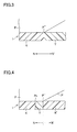
- FIG. 2 is a cross section of the main portion of a belt embodying the invention which includes a hard inner portion and an outer portion of less hardness, the outer portion extending outward from a point slightly inward relative to the adjacent end of the cylindrical part of the press roll;
- FIG. 3 is a cross section of the main portion of a belt embodying the invention, which includes a hard inner portion and an outer portion of less hardness, the outer portion extending outward from a point coinciding with the adjacent end of the cylindrical part of the press roll;
- FIG. 4 is a cross section of the main portion of a belt embodying the invention, which includes a hard inner portion and a portion of less hardness, extending from a point slightly inward relative to the adjacent end of the cylindrical part of the press roll, to the outer end of the cylindrical part of the press roll;
- FIG. 5 is a cross section of the main portion of a belt embodying the invention, and including a thin outer portion, the belt including a tapered portion extending outward from a point located inward relative to the adjacent end of the cylindrical part of the press roll;
- FIG. 6 is a cross section of a main portion of a belt embodying the invention, and including a thin outer portion, the belt including a tapered portion extending outward from a point coinciding with the adjacent end of the cylindrical part of the press roll;
- FIG. 7 is a cross section of the main portion of a belt embodying the invention, and including a tapered portion which extends from a point located inward relative to the adjacent end of the cylindrical part of the press roll.
- the outer edge of the tapered portion is also on the inside relative to the adjacent end of the cylindrical part of the press roll;
- FIG. 8 is a schematic view of the main portion of a shoe press incorporating a long type shoe press belt
- FIG. 9 is a schematic view of the main portion of a shoe press incorporating a short type shoe press belt.
- FIG. 10 is a schematic view showing the relationship of a press roll, a shoe and a shoe press belt.
- Embodiments of the invention are described below with reference to FIGs. 1 - 7.
- Each of the belts in accordance with the invention is designed for use with one of the shoe presses 91, shown in FIGS. 8 and 9, in which the nip zone N, formed between the press roll P and the shoe S, is narrower than the shoe.
- Each belt includes a body 11, as shown in FIG. 1, and, in each of FIGs. 1 - 4, the belt body 11 comprises a hard portion K, and a portion Y having a hardness less than that of portion K.
- the hard portion K is a central portion
- the belt has two portions K, having less hardness, the two portions extending along the central portion in side-by-side relationship with the central portion.
- the portion Y is positioned so that a part of the portion Y is directly opposite the nip end, at the boundary P" between the nip zone N and the non-nip zone N'.
- the belt body 11 comprises a thin portion H and a thick portion T.
- the thin portion H is positioned so that a part of the thin portion is directly opposite the nip end, at the boundary P" between the nip zone N and the non-nip zone N'.
- the thick portion T is uniform in thickness, the thin portion H varies in thickness, and includes all, or at least part of, a tapered transition connecting the outer part of the thin portion with the thick portion.
- the belt body 11 includes a base body 12 and a high molecular weight elastic material 13.
- the elastic material 13 may be rubber or another elastomer, and is preferably a polyurethane resin.
- the base body 12 imparts strength to the belt body 11 and may be any one of a number of known structures.
- the base body 12 may be a woven fabric having a warp and weft, a fabric formed of a warp and weft superimposed on each other, or a fabric formed from a ribbon of cloth wound in a spiral.
- the belt body 11 can be produced by a process in which both sides of the base body 12 are coated and filled with a high molecular weight elastic material 13.
- the upper and lower layers of the elastic material 13 are joined to each other at the filling yarns (not shown) in the base body 12, and cover both sides of the base body 12.
- water holding grooves may be formed in the surface of the outwardly facing elastic layer of the belt.
- the belt body 11 may be manufactured by filling the base body 12 with high molecular weight elastic material 13 from only the upper side of the base body, while causing the elastic material to accumulate on both sides of the base.
- the belt may have a high molecular weight elastic material 13 only on the press roll side of the base fabric so that base body is exposed on the shoe side.
- the belt may have a high molecular weight elastic material 13 on the press roll side of the base fabric, while the shoe-facing side may have a high molecular weight elastic material almost flush with the shoe-facing surface of the base fabric.
- the belt body 11 comprises a hard portion K and a portion Y having less hardness than that of portion K.
- the less hard portion Y extends through distance "a", spanning the nip end of the press roll P at boundary P".
- the difference in hardness between the less hard and hard portions Y and K depends on the selection of the high molecular weight elastic material.
- the less hard and hard portions Y and K may be resins that soften with heat to different degrees. The difference between the degrees of softening of the two portions of the belt results in a difference in hardness between the portions Y and K when the belt is in operation.
- the portions Y and K may be made from identical materials or from high molecular weight elastic materials having identical properties, including hardness.
- the portion Y may be made less hard by the presence of air bubbles or other voids, while the hard portion K is more dense. In this case, a difference in the mechanical structure between the portions Y and K of the belt body results in a difference in hardness.
- the high molecular weight elastic material may be formed with air bubbles or other voids in it by including hollow fillers or hollow microcapsules in the material, by including a foaming agent in the material, or by introducing air bubbles into the material by means of an air mixing machine.
- the diameters of the air bubbles or other voids vary with the type and hardness of the selected high molecular weight elastic material, the function of the belt, and other factors. In general, it is preferred that the diameters range from 10 to 100 ⁇ m.
- the optimum ratio of the voids to the high molecular weight elastic material is achieved where the hollow fillers constitute from about 0.5 to 50 percent by weight of the material of the portion Y.
- the bubbles should be present in an amount in the range from approximately 0.2 to about 30 percent by volume of the material of the portion Y.
- the voids in the less hard portion Y be independent of each other, so that cracks do not propagate from one void to the other voids.
- the independent voids are formed by the use of hollow fillers or hollow microcapsules, the voids are more uniform in size, and consequently, a consistent quality can be more easily achieved in the less hard portion Y.
- the belt body 11 may comprises an outer less hard portion Y, and a hard portion K positioned within the nip zone N of the press roll P.
- the belt body 11 may comprise a first hard portion K, a less hard portion Y and a second hard portion K'.
- the first hard portion K is inside the nip zone N, while at least part of the second hard portion K' is within the non-nip zone N'.
- the latter form of belt is preferred for use in a shoe press requiring that the belt edges be strong when the belt is fitted to the press.
- the hard portions K and K' should have a hardness between 85° and 98° (JIS-A). It is also preferable that the less hard portions Y should have a hardness between 80° and 95° (JIS-A).
- the difference in hardness between the hard and less hard portions K (and K') and Y should preferably range between about 1 and about 5 degrees.
- FIG. 2 shows a belt comprising an outer, less hard portion Y and an inner, hard portion K.
- the boundary between the hard portion K and the less hard portion Y of the belt is located at a point Pn to the inside of the nip end boundary P" of the press roll P.
- the less hard portion Y spans the boundary P" at the adjacent nip end.
- FIG. 3 shows another belt comprising an outer, less hard, portion Y and an inner, hard portion K.
- the boundary between the hard portion K and the less hard portion Y of this belt is coincides with the nip end boundary P" of the press roll P.
- This belt is another embodiment in which the less hard portion Y is directly opposite the nip end boundary P".
- FIG. 4 shows a belt comprising a first hard portion K, a less hard portion Y, and a second hard portion K'.
- the first hard portion K is to the inside on the belt relative to the less hard portion Y.
- the boundary between the first hard portion K and the less hard portion Y of this belt is located at a point Pn to the inside of the nip end boundary P".
- the boundary between the less hard portion Y and the adjacent second hard portion K' coincides with the adjacent nip end boundary P".
- each of the hard and less hard portions K (and K') and Y may be uniform in hardness. Alternatively, there may be hardness gradients at the boundaries between the portions K (and K') and Y.
- FIGs. 5 - 7 show belt bodies 11 each comprising an outer thin portion H and an inner thick portion T, where part of the thin portion is directly opposite to the nip end boundary P" between the nip zone N and the non-nip zone N'.
- the inner thick portion T extends to a point Pn, which is to the inside of the adjacent nip end boundary P" of the press roll P. From point Pn, the belt is tapered at D from an edge D1 to an edge D2. From edge D2 outward, the belt is of a uniform thickness less than that of thick portion T.
- the outer thin portion H includes not only the outer portion of uniform thickness, but also a part of the tapered portion of the belt. In this embodiment, the belt is out of direct contact with the nip end of the belt.
- the belt includes a tapered portion D between the inner thick portion T and an outer thin portion of uniform thickness.
- the tapered portion D extends from edge D1, which coincides the adjacent nip end boundary P" of the press roll P, to edge D2.
- the thin portion of the belt includes the entire tapered portion. Because the tapered portion D begins at a point coinciding with the adjacent nip end boundary P", a shearing force exerted by the roll P will have less effect on the belt than it would if the belt were of uniform thickness throughout its width.
- the belt also includes a tapered portion D between the inner thick portion of the belt and an outer portion of uniform thickness less than the thickness of the inner thick portion.
- the tapered portion D extends from edge D1, at a point Pn to the inside of the adjacent nip end boundary P", to edge D2.
- This belt is similar to that shown in FIG. 5, in that the belt is out of direct contact with the nip end of the belt.
- the belt of FIG. 7 differs from the belt of FIG. 5 in that the edge D2 of the tapered portion D in FIG. 7 is to the inside of the nip end boundary P". Accordingly, the distance "b" between the thin outer portion of the belt and the adjacent nip end boundary P" in FIG. 7 is greater than that in FIG. 5.
- the angle of rake of the tapered portion D may be varied according to the hardness of the selected high molecular weight elastic material, and according to other factors, but preferably falls within the range of 0.4 and 0.5 degrees. It has been verified by experiment that the maximum thickness difference between the edges D1 and D2 of the tapered portion D is preferably about 1.5 mm.
- Another belt (not shown) embodying the invention comprises a central thick portion, a thin portion in the form of a recess to the outside of the thick portion, and another outer thick portion outside the outer thin portion.
- the recess should be located so that a part of the recess is directly opposite the nip end boundary P".
- the shoe press belt according to the invention which is characterized by a body comprising a hard portion and a portion of less hardness, a part of the less hard portion being directly opposite the boundary between the nip and non-nip zones, has the outstanding advantage that it does not tend to form cracks even though it is subjected to a continuous shearing force due to the fact that the nip zone width is less than the shoe width.
- the less hard portion of the belt which avoids the adverse effects of the shearing force applied by the nip end of the roll, can be produced easily by utilizing different high molecular weight elastic materials for the hard and less hard portions of the belt.
- the difference in hardness between the two portions of the belt can be achieved by utilizing a dense high molecular weight elastic material for the hard portion of the belt and forming the less hard portion from a high molecular weight elastic material having voids formed therein.
- the less hard portion which avoids the adverse effects of the shearing force applied at the nip end of the press roll, can be easily produced mechanically by filling the portion of the belt which is to be less hard with air bubbles or other voids.
- the belt is either out of direct contact with the nip end of the press roll or, if in contact, not subject to severe shearing forces.
Landscapes
- Paper (AREA)
- Footwear And Its Accessory, Manufacturing Method And Apparatuses (AREA)
- Casting Or Compression Moulding Of Plastics Or The Like (AREA)
Applications Claiming Priority (2)
| Application Number | Priority Date | Filing Date | Title |
|---|---|---|---|
| JP2001232599A JP2003049380A (ja) | 2001-07-31 | 2001-07-31 | シュープレス用ベルト |
| JP2001232599 | 2001-07-31 |
Publications (3)
| Publication Number | Publication Date |
|---|---|
| EP1281809A2 true EP1281809A2 (fr) | 2003-02-05 |
| EP1281809A3 EP1281809A3 (fr) | 2003-02-12 |
| EP1281809B1 EP1281809B1 (fr) | 2011-06-22 |
Family
ID=19064496
Family Applications (1)
| Application Number | Title | Priority Date | Filing Date |
|---|---|---|---|
| EP02255326A Expired - Lifetime EP1281809B1 (fr) | 2001-07-31 | 2002-07-30 | Bande pour presse à patin et presse à patin |
Country Status (6)
| Country | Link |
|---|---|
| US (1) | US6736939B2 (fr) |
| EP (1) | EP1281809B1 (fr) |
| JP (1) | JP2003049380A (fr) |
| KR (2) | KR100874579B1 (fr) |
| CN (2) | CN1285802C (fr) |
| CA (2) | CA2697840C (fr) |
Cited By (2)
| Publication number | Priority date | Publication date | Assignee | Title |
|---|---|---|---|---|
| EP1502990A4 (fr) * | 2002-04-11 | 2005-08-17 | Yamauchi Corp | Courroies de pressage et dispositif de pressage a sabot utilisant ces courroies |
| EP1854918A4 (fr) * | 2005-03-04 | 2008-10-08 | Yamauchi Corp | Bande pressante et rouleau presseur à patin |
Families Citing this family (7)
| Publication number | Priority date | Publication date | Assignee | Title |
|---|---|---|---|---|
| US7611608B2 (en) * | 2003-08-07 | 2009-11-03 | Yamauchi Corporation | Press belt, process for producing the same and shoe press roll using the press belt |
| JP3825435B2 (ja) * | 2003-09-04 | 2006-09-27 | ヤマウチ株式会社 | プレスベルトおよびシュープレスロール |
| CN1673452B (zh) * | 2004-03-26 | 2013-11-06 | 市川毛织株式会社 | 靴形压榨带 |
| DE102005046812A1 (de) * | 2005-09-30 | 2007-04-05 | Voith Patent Gmbh | Band zum Überführen einer herzustellenden Faserstoffbahn |
| DE102005046905A1 (de) * | 2005-09-30 | 2007-04-05 | Voith Patent Gmbh | Papiermaschinenbespannung |
| AT505760B1 (de) * | 2008-01-09 | 2009-04-15 | Andritz Ag Maschf | Vorrichtung und verfahren zur entwasserung einer materialbahn |
| JP5731773B2 (ja) * | 2010-09-02 | 2015-06-10 | ヤマウチ株式会社 | プレスベルト及びシュープレスロール並びにプレスベルトの製造方法 |
Family Cites Families (12)
| Publication number | Priority date | Publication date | Assignee | Title |
|---|---|---|---|---|
| US4330023A (en) * | 1980-08-18 | 1982-05-18 | Beloit Corporation | Extended nip press |
| JPS61252389A (ja) * | 1985-04-25 | 1986-11-10 | 市川毛織株式会社 | 抄紙用加圧ベルト |
| US4877472A (en) * | 1988-10-31 | 1989-10-31 | Beloit Corporation | Method of making a bearing blanket |
| US4944844A (en) * | 1989-07-11 | 1990-07-31 | Beloit Corporation | Polyurethane extended nip press blanket |
| DE4401580A1 (de) * | 1994-01-20 | 1994-06-01 | Voith Gmbh J M | Langspaltpresse zum Auspressen einer laufenden Bahn, insbesondere einer Papierbahn |
| DE4443598C2 (de) * | 1994-12-07 | 2000-05-25 | Voith Sulzer Papiermasch Gmbh | Verfahren zur Herstellung eines Preßmantels |
| DE19637477A1 (de) * | 1996-09-13 | 1998-03-19 | Voith Sulzer Papiermasch Gmbh | Preßmantel für eine Preßvorrichtung |
| DE19652545B4 (de) * | 1996-12-17 | 2006-03-23 | Voith Sulzer Papiermaschinen Gmbh | Preßwalze zum Behandeln bahnförmigen Gutes |
| JP3045975B2 (ja) * | 1997-04-24 | 2000-05-29 | 市川毛織株式会社 | シュープレス用ベルト |
| DE19728399A1 (de) * | 1997-07-03 | 1999-01-07 | Voith Sulzer Papiermasch Gmbh | Maschine zur Herstellung einer kontinuierlichen Materialbahn |
| JP2001089989A (ja) * | 1999-09-20 | 2001-04-03 | Ichikawa Woolen Textile Co Ltd | 湿紙搬送ベルト及びその製造方法 |
| JP3507432B2 (ja) * | 2000-12-13 | 2004-03-15 | ヤマウチ株式会社 | 製紙用弾性ベルト |
-
2001
- 2001-07-31 JP JP2001232599A patent/JP2003049380A/ja active Pending
-
2002
- 2002-07-29 CN CNB021258597A patent/CN1285802C/zh not_active Expired - Fee Related
- 2002-07-29 US US10/208,722 patent/US6736939B2/en not_active Expired - Lifetime
- 2002-07-29 CN CNA2005100934873A patent/CN1737256A/zh active Pending
- 2002-07-30 KR KR1020020044915A patent/KR100874579B1/ko not_active Expired - Fee Related
- 2002-07-30 EP EP02255326A patent/EP1281809B1/fr not_active Expired - Lifetime
- 2002-07-31 CA CA2697840A patent/CA2697840C/fr not_active Expired - Lifetime
- 2002-07-31 CA CA2396607A patent/CA2396607C/fr not_active Expired - Lifetime
-
2008
- 2008-07-30 KR KR1020080074551A patent/KR20080075826A/ko not_active Ceased
Non-Patent Citations (1)
| Title |
|---|
| None |
Cited By (2)
| Publication number | Priority date | Publication date | Assignee | Title |
|---|---|---|---|---|
| EP1502990A4 (fr) * | 2002-04-11 | 2005-08-17 | Yamauchi Corp | Courroies de pressage et dispositif de pressage a sabot utilisant ces courroies |
| EP1854918A4 (fr) * | 2005-03-04 | 2008-10-08 | Yamauchi Corp | Bande pressante et rouleau presseur à patin |
Also Published As
| Publication number | Publication date |
|---|---|
| CN1400358A (zh) | 2003-03-05 |
| KR20030011687A (ko) | 2003-02-11 |
| KR100874579B1 (ko) | 2008-12-16 |
| US20030024677A1 (en) | 2003-02-06 |
| CA2396607C (fr) | 2011-09-13 |
| CN1285802C (zh) | 2006-11-22 |
| JP2003049380A (ja) | 2003-02-21 |
| CA2697840C (fr) | 2011-11-22 |
| EP1281809A3 (fr) | 2003-02-12 |
| US6736939B2 (en) | 2004-05-18 |
| CN1737256A (zh) | 2006-02-22 |
| KR20080075826A (ko) | 2008-08-19 |
| CA2697840A1 (fr) | 2003-01-31 |
| EP1281809B1 (fr) | 2011-06-22 |
| CA2396607A1 (fr) | 2003-01-31 |
Similar Documents
| Publication | Publication Date | Title |
|---|---|---|
| US4880501A (en) | Press cover for a press for dewatering web material | |
| US5298124A (en) | Transfer belt in a press nip closed draw transfer | |
| US5062924A (en) | Blanket for an extended nip press with anisotropic woven base layers | |
| EP1085124A2 (fr) | Bande de transfert et procédé pour sa fabrication | |
| US6383339B1 (en) | Transfer belt | |
| US6428874B1 (en) | Grooved long nip shoe press belt | |
| EP1281809B1 (fr) | Bande pour presse à patin et presse à patin | |
| JP3045975B2 (ja) | シュープレス用ベルト | |
| JP2002327389A (ja) | シュープレス用ベルト | |
| EP0886004A1 (fr) | Bande pour une presse à patin | |
| US6929718B2 (en) | Shoe press belt | |
| JP4949848B2 (ja) | 可変な第一溝を有するベルト | |
| CA1262648A (fr) | Methode et dispositif, ainsi qu'element de courroie, pour equilibrer l'effort de compression dans la presse essoreuse d'une machine a papier | |
| US7005042B2 (en) | Nip press belt | |
| CA2383771C (fr) | Courroie de calandrage | |
| US7014734B2 (en) | Shoe press belt | |
| CA2365951C (fr) | Bande de transfert | |
| US20090123706A1 (en) | Papermaking Felt |
Legal Events
| Date | Code | Title | Description |
|---|---|---|---|
| PUAI | Public reference made under article 153(3) epc to a published international application that has entered the european phase |
Free format text: ORIGINAL CODE: 0009012 |
|
| PUAL | Search report despatched |
Free format text: ORIGINAL CODE: 0009013 |
|
| AK | Designated contracting states |
Designated state(s): AT BE BG CH CY CZ DE DK EE ES FI FR GB GR IE IT LI LU MC NL PT SE SK TR |
|
| AX | Request for extension of the european patent |
Extension state: AL LT LV MK RO SI |
|
| AK | Designated contracting states |
Designated state(s): AT BE BG CH CY CZ DE DK EE ES FI FR GB GR IE IT LI LU MC NL PT SE SK TR |
|
| AX | Request for extension of the european patent |
Extension state: AL LT LV MK RO SI |
|
| 17P | Request for examination filed |
Effective date: 20030416 |
|
| AKX | Designation fees paid |
Designated state(s): DE FI SE |
|
| RTI1 | Title (correction) |
Free format text: SHOE PRESS BELT AND SHOE PRESS |
|
| GRAP | Despatch of communication of intention to grant a patent |
Free format text: ORIGINAL CODE: EPIDOSNIGR1 |
|
| GRAS | Grant fee paid |
Free format text: ORIGINAL CODE: EPIDOSNIGR3 |
|
| GRAA | (expected) grant |
Free format text: ORIGINAL CODE: 0009210 |
|
| AK | Designated contracting states |
Kind code of ref document: B1 Designated state(s): DE FI SE |
|
| REG | Reference to a national code |
Ref country code: DE Ref legal event code: R096 Ref document number: 60240328 Country of ref document: DE Effective date: 20110804 |
|
| REG | Reference to a national code |
Ref country code: SE Ref legal event code: TRGR |
|
| PLBE | No opposition filed within time limit |
Free format text: ORIGINAL CODE: 0009261 |
|
| STAA | Information on the status of an ep patent application or granted ep patent |
Free format text: STATUS: NO OPPOSITION FILED WITHIN TIME LIMIT |
|
| 26N | No opposition filed |
Effective date: 20120323 |
|
| REG | Reference to a national code |
Ref country code: DE Ref legal event code: R097 Ref document number: 60240328 Country of ref document: DE Effective date: 20120323 |
|
| PGFP | Annual fee paid to national office [announced via postgrant information from national office to epo] |
Ref country code: DE Payment date: 20160726 Year of fee payment: 15 Ref country code: FI Payment date: 20160711 Year of fee payment: 15 |
|
| PGFP | Annual fee paid to national office [announced via postgrant information from national office to epo] |
Ref country code: SE Payment date: 20160712 Year of fee payment: 15 |
|
| REG | Reference to a national code |
Ref country code: DE Ref legal event code: R119 Ref document number: 60240328 Country of ref document: DE |
|
| REG | Reference to a national code |
Ref country code: SE Ref legal event code: EUG |
|
| PG25 | Lapsed in a contracting state [announced via postgrant information from national office to epo] |
Ref country code: DE Free format text: LAPSE BECAUSE OF NON-PAYMENT OF DUE FEES Effective date: 20180201 Ref country code: FI Free format text: LAPSE BECAUSE OF NON-PAYMENT OF DUE FEES Effective date: 20170730 Ref country code: SE Free format text: LAPSE BECAUSE OF NON-PAYMENT OF DUE FEES Effective date: 20170731 |