EP1281825A2 - Verrigelbare Türgriffvorrichtung mit inegriertem Kombinationsschloss - Google Patents
Verrigelbare Türgriffvorrichtung mit inegriertem Kombinationsschloss Download PDFInfo
- Publication number
- EP1281825A2 EP1281825A2 EP02255283A EP02255283A EP1281825A2 EP 1281825 A2 EP1281825 A2 EP 1281825A2 EP 02255283 A EP02255283 A EP 02255283A EP 02255283 A EP02255283 A EP 02255283A EP 1281825 A2 EP1281825 A2 EP 1281825A2
- Authority
- EP
- European Patent Office
- Prior art keywords
- lock
- door handle
- door
- plate
- locking
- Prior art date
- Legal status (The legal status is an assumption and is not a legal conclusion. Google has not performed a legal analysis and makes no representation as to the accuracy of the status listed.)
- Granted
Links
Images









Classifications
-
- E—FIXED CONSTRUCTIONS
- E05—LOCKS; KEYS; WINDOW OR DOOR FITTINGS; SAFES
- E05B—LOCKS; ACCESSORIES THEREFOR; HANDCUFFS
- E05B13/00—Devices preventing the key or the handle or both from being used
- E05B13/10—Devices preventing the key or the handle or both from being used formed by a lock arranged in the handle
- E05B13/103—Combination lock
-
- E—FIXED CONSTRUCTIONS
- E05—LOCKS; KEYS; WINDOW OR DOOR FITTINGS; SAFES
- E05B—LOCKS; ACCESSORIES THEREFOR; HANDCUFFS
- E05B5/00—Handles completely let into the surface of the wing
-
- E—FIXED CONSTRUCTIONS
- E05—LOCKS; KEYS; WINDOW OR DOOR FITTINGS; SAFES
- E05B—LOCKS; ACCESSORIES THEREFOR; HANDCUFFS
- E05B1/00—Knobs or handles for wings; Knobs, handles, or press buttons for locks or latches on wings
- E05B1/0092—Moving otherwise than only rectilinearly or only rotatively
-
- E—FIXED CONSTRUCTIONS
- E05—LOCKS; KEYS; WINDOW OR DOOR FITTINGS; SAFES
- E05B—LOCKS; ACCESSORIES THEREFOR; HANDCUFFS
- E05B37/00—Permutation or combination locks; Puzzle locks
- E05B37/0031—Locks with both permutation and key actuation
- E05B37/0034—Locks with both permutation and key actuation actuated by either
-
- E—FIXED CONSTRUCTIONS
- E05—LOCKS; KEYS; WINDOW OR DOOR FITTINGS; SAFES
- E05B—LOCKS; ACCESSORIES THEREFOR; HANDCUFFS
- E05B37/00—Permutation or combination locks; Puzzle locks
- E05B37/0048—Permutation or combination locks; Puzzle locks with changeable combination
- E05B37/0058—Permutation or combination locks; Puzzle locks with changeable combination by axial disengagement between hub and rim of tumbler discs or rings
-
- E—FIXED CONSTRUCTIONS
- E05—LOCKS; KEYS; WINDOW OR DOOR FITTINGS; SAFES
- E05B—LOCKS; ACCESSORIES THEREFOR; HANDCUFFS
- E05B37/00—Permutation or combination locks; Puzzle locks
- E05B37/02—Permutation or combination locks; Puzzle locks with tumbler discs or rings arranged on a single axis, each disc being adjustable independently of the others
-
- Y—GENERAL TAGGING OF NEW TECHNOLOGICAL DEVELOPMENTS; GENERAL TAGGING OF CROSS-SECTIONAL TECHNOLOGIES SPANNING OVER SEVERAL SECTIONS OF THE IPC; TECHNICAL SUBJECTS COVERED BY FORMER USPC CROSS-REFERENCE ART COLLECTIONS [XRACs] AND DIGESTS
- Y10—TECHNICAL SUBJECTS COVERED BY FORMER USPC
- Y10S—TECHNICAL SUBJECTS COVERED BY FORMER USPC CROSS-REFERENCE ART COLLECTIONS [XRACs] AND DIGESTS
- Y10S292/00—Closure fasteners
- Y10S292/30—Latch and handle
-
- Y—GENERAL TAGGING OF NEW TECHNOLOGICAL DEVELOPMENTS; GENERAL TAGGING OF CROSS-SECTIONAL TECHNOLOGIES SPANNING OVER SEVERAL SECTIONS OF THE IPC; TECHNICAL SUBJECTS COVERED BY FORMER USPC CROSS-REFERENCE ART COLLECTIONS [XRACs] AND DIGESTS
- Y10—TECHNICAL SUBJECTS COVERED BY FORMER USPC
- Y10S—TECHNICAL SUBJECTS COVERED BY FORMER USPC CROSS-REFERENCE ART COLLECTIONS [XRACs] AND DIGESTS
- Y10S292/00—Closure fasteners
- Y10S292/31—Lever operator, flush
-
- Y—GENERAL TAGGING OF NEW TECHNOLOGICAL DEVELOPMENTS; GENERAL TAGGING OF CROSS-SECTIONAL TECHNOLOGIES SPANNING OVER SEVERAL SECTIONS OF THE IPC; TECHNICAL SUBJECTS COVERED BY FORMER USPC CROSS-REFERENCE ART COLLECTIONS [XRACs] AND DIGESTS
- Y10—TECHNICAL SUBJECTS COVERED BY FORMER USPC
- Y10T—TECHNICAL SUBJECTS COVERED BY FORMER US CLASSIFICATION
- Y10T70/00—Locks
- Y10T70/50—Special application
- Y10T70/5611—For control and machine elements
- Y10T70/5757—Handle, handwheel or knob
- Y10T70/5761—Retractable or flush handle
-
- Y—GENERAL TAGGING OF NEW TECHNOLOGICAL DEVELOPMENTS; GENERAL TAGGING OF CROSS-SECTIONAL TECHNOLOGIES SPANNING OVER SEVERAL SECTIONS OF THE IPC; TECHNICAL SUBJECTS COVERED BY FORMER USPC CROSS-REFERENCE ART COLLECTIONS [XRACs] AND DIGESTS
- Y10—TECHNICAL SUBJECTS COVERED BY FORMER USPC
- Y10T—TECHNICAL SUBJECTS COVERED BY FORMER US CLASSIFICATION
- Y10T70/00—Locks
- Y10T70/70—Operating mechanism
- Y10T70/7141—Combination and key
-
- Y—GENERAL TAGGING OF NEW TECHNOLOGICAL DEVELOPMENTS; GENERAL TAGGING OF CROSS-SECTIONAL TECHNOLOGIES SPANNING OVER SEVERAL SECTIONS OF THE IPC; TECHNICAL SUBJECTS COVERED BY FORMER USPC CROSS-REFERENCE ART COLLECTIONS [XRACs] AND DIGESTS
- Y10—TECHNICAL SUBJECTS COVERED BY FORMER USPC
- Y10T—TECHNICAL SUBJECTS COVERED BY FORMER US CLASSIFICATION
- Y10T70/00—Locks
- Y10T70/70—Operating mechanism
- Y10T70/7147—Combination or key
Definitions
- the present invention relates to a door locking handle assembly with a built-in combination lock of the pull-out and side-swinging lever-action type, in which a door handle is pivoted to a base body of the assembly so as to be pulled out forward and pushed back rearward relative to the base body and turned on its pivoted end.
- a door locking handle assembly of a conventional type shown in U.S. Patent No.5,467,623, herein incorporated by reference has a construction in which a base body of the assembly is fixedly mounted on a door of a box or container; a door handle is pivoted to the base body so as to be pulled out forward and pushed back rearward relative to the base body and further turned sideward on its pivoted end after completion of its pulling-out operation; when the door handle is pulled out of the base body to assume its pulled-up or raised inclination position relative to the base body and turned sideward after completion of its pulling-out operation, a catch plate (i.e.
- a locking member which serves as a door bolt directly or indirectly connected with the door handle is released from a receiving portion of a stationary frame element (i.e. door frame) of the box or container.
- a cylinder lock is incorporated in either the door handle or the base body.
- the door handle is pushed back rearward relative to the base body and held in its folded position or locked position in the base body.
- the present invention was made. Consequently, it is an object of the present invention to provide a door locking handle assembly with a built-in combination lock, which assembly is thin as a whole and capable of providing a very large number of available keys for the combination lock, wherein a large number of eligible persons or users of various instruments contained in a box or container provided with the door locking handle assembly are precisely controlled by a control operator through a computerized personal management system.
- a door locking assembly with a built-in combination lock comprising a base body which is fixedly mounted on a door of a box, wherein a door handle is pivoted to the base body so as to be capable of being pulled out forward and pushed back rearward relative to the base body and also turning sideward on a locking shaft after completion of its pulling-out operation, wherein a locking member serving as a door bolt for locking the door to a main body of the box is directly or indirectly connected with the door handle so as to be engaged with and disengaged from a receiving portion of a stationary frame element such as the main body of the box when the door handle is pulled out forward and then turn sideward on the locking shaft after completion of the pulling-out operation of the door handle, wherein:
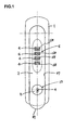
- an embodiment of a door locking handle assembly with a built-in combination lock 6 is provided with a base body 1.
- the base body 1 is fixedly mounted on a door 30 (shown in dotted lines in Fig. 4) of a box or container(not shown).
- a door handle 2 is pivoted to the base body 1 so as to be capable of being pulled out forward and pushed back rearward relative to the base body 1 and also turning sideward on a locking shaft 29 after completion of its pulling-out operation.
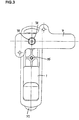
- a locking member 3 (shown in Fig. 3) serves as a door bolt for locking the door 30 to a main body of the box, and is directly or indirectly connected with the door handle 2 so as to be engaged with and disengaged from a receiving portion of a stationary frame element such as the main body of the box (not shown) when the door handle 2 is pulled out forward and turned sideward on the locking shaft 29 after completion of the pulling-out operation of the door handle 2.
- the combination lock 6 is provided with a plurality of marked dial discs 4, incorporated in the door handle 2 and opened by turning each of the marked dial discs 4 a given number of times to establish a predetermined unique combination of marks provided in outer peripheral surfaces of the dial discs 4.
- the combination lock 6 is held in its locked condition when the predetermined combination of marks of the dial discs 4 is not established.
- the door locking handle assembly is further provided with a cylinder lock 13.
- This cylinder lock 13 is incorporated in the door handle 2 so as to be disposed adjacent to the combination lock 6 in a longitudinal direction of the door handle 2, and is provided with a rotor 8.
- a stopping plate 11 which is slidably received in a side through-hole 12 of the door handle 2 is driven in a manner such that the stopping plate 11 is projected outward from the side through-hole 12 and retracted from the outside of the door handle 2.
- the stopping plate 11 has its upper end portion abut against a shoulder portion 15 of a lower surface of a proximal end portion of a receiver lever 16.
- This lever 16 has its proximal end portion pivoted to an inner wall portion of the base body 1 through a first pivot 17.
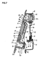
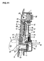
- the shoulder portion 15 of the receiver lever 16 is provided with a cam slope 18 through which the receiver lever 16 is pushed upward by the upper end portion of the stopper plate 11 when the door handle 2 is pulled forward. Further, the receiver lever 16 is rotatably urged downward toward the stopper plate 11 by means of a first spring member 19, as shown in Fig. 4.
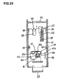
- a slider 21 is disposed in parallel with a center pin 20 of the combination lock 6, and urged downward toward the cylinder lock 13 by means of a second spring member 22 (shown in Fig. 23) in a manner such that a lower end portion of the slider 21 abuts against an upper surface of the receiver lever 16 (see, Fig. 5).
- the slider 21 has its restriction portion 26 engaged with and disengaged from a locking end portion 25 of the lock plate 5 when the lock plate 5 is held in its locked position and its unlocked position, respectively.
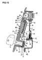
- the lock plate 5 when the lock plate 5 is held in its unlocked position, it is possible to pull the door handle 2 forward out of the base body 1. As shown in Fig. 5, when the door handle 2 is thus pulled forward, the stopper plate 11 pushes the cam slope 18 of the receiver lever 16 swingably upward so that the receiver lever 16 is moved to its unlocked position. On the other hand, as shown in Fig. 8, when the lock plate 5 is held in its locked position, the lock plate 5 has its locking end portion 25 engaged with the restriction portion 26 of the slider 21 to prevent the receiver lever 16 from turning on the first pivot 17.
- a control operator of the instruments housed in the box is capable of allocating to each of a large number of eligible users or persons such a predetermined unique combination of marks of the marked dial discs 4 of the combination lock 6 for unlocking and locking the combination lock 6.
- Each of the eligible users or persons is capable of unlocking the combination lock 6 of the door locking handle assembly by turning in a normal or a reverse direction each of the marked dial discs 4 a given number of times to establish the unique combination of the marks, which combination has been allocated to each of the eligible users or persons, wherein the marks are provided in an outer peripheral surface of each of the dial discs 4.
- the combination lock 6 is unlocked and therefore capable of moving to its unlocked position.
- the locking end portion 25 of the lock plate 5 is in a predetermined advanced position in which the locking end portion 25 of the lock plate 5 is released from the restriction portion 26 of the slider 21; and the slider 21 is capable of moving upward as viewed in Fig. 4.
- the cylinder lock 13 is in its locked condition, so that the upper end portion 14 of the stopping plate 11 is engaged with the shoulder portion 15 of the receiver lever 16 under the influence of a resilient force exerted by the first spring member 19.
- the door handle 2 is held in its folded position inside a front concave portion 27 of the base body 1.
- the receiver lever 16 is released from a pushing force exerted by the upper end portion 14 of the stopping plate 11. Due to this, as is clear from Fig. 7, the receiver lever 16 swingably returns to its initial rest position under the influence of a resilient force exerted by the first spring member 19. At this time, the slider 21 also returns downward to its initial lower position under the influence of a resilient force exerted by the second spring member 22 (shown in Fig. 23).
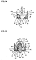
- the lock plate 5 rotates in the direction of the arrow as shown in Fig. 14 to lock the combination lock 6. Due to this, the lock plate 5 has its locking end portion 25 abut against the restriction portion of the slider 21 to prevent the receiver lever 16 from turning upward on the first pivot 17 toward its escape position.
- the control operator of the instruments housed in the box who allocates to each of the users or persons the predetermined unique combination of marks of the dial discs 4, has a broader control power than does each of the users or persons. Consequently, the control operator is capable of pulling forward and turning sideward the door handle 2 to open the door 30 without using the combination of the marks of the dial discs 4. Furthermore, the control operator is authorized to have the eligible key 7 of the cylinder lock 13.
- the control operator inserts the key 7 into the keyhole 9 (shown in Fig. 1) of the rotor 8 in the cylinder lock 13 to unlock the internal lock mechanism 10 of the cylinder lock 13 by using a predetermined coded key ridge portion of the key 7. This makes it possible for the rotor 8 of the cylinder lock 13 to rotate on its longitudinal center axis.
- an appropriate reset means such as a reset lever 63 (shown in Fig. 24) is operated from behind the thus opened door 30 so that the combination lock 6 is released from such an accidental locking condition.
- a bearing hole 31 is formed in an upper portion of the base body 1 to extend in a direction perpendicular to the plane of the front surface of the door 30.
- a locking shaft 29 Rotatably inserted in such a bearing hole 31 of the base body 1 is a locking shaft 29 which is not axially slidable in the bearing hole 31.
- the locking shaft 29 is provided with a square-column portion 29a in its rear end portion.
- the base body 1 is mounted in an elongated front receiving hole 33 of the door 30 from the front side of the door 30
- a mounting plate 34 assuming a U-shaped form in cross section is mounted on a rear surface of the door 30 to mate with the base body 1, and then fixed to the door 30 by means of a suitable fastening means such as a screw 35 or the like, as shown in Figs. 2 and 3.
- a concave portion 36 As shown in Fig. 4, formed in an upper rear portion of the door handle 2 is a concave portion 36.
- This concave portion 36 assumes a substantially fan-like shape in longitudinal section to swingably receive therein a front end portion of the locking shaft 29.
- the door handle 2 has its upper end portion corresponding to its concave portion 36 pivoted to the front end portion of the locking shaft 29 through a second pivot or cross pivot 28.
- This cross pivot 28 extends in parallel with a front surface of the door 30 in a direction perpendicular to the longitudinal axis of the door handle 2.
- a flange 37 serving as a fingertip engaging edge portion 37, which bulges out downward in the longitudinal direction of the door handle 2.
- the fingertip engaging edge portion 37 of the door handle 2 is still spaced apart forward from a front surface of the corresponding lower portion of the base body 1, which enables the person or user to pick up the lower free end portion of the door handle 2 in an easy manner.
- an elongated hollow portion 38 for receiving therein a combination lock 6.
- the hollow portion 38 of the door handle 2 is open at the rear side of the door handle 2 to form an opening which is covered by a back plate member 39, as shown in Fig. 7.
- the combination lock 6 is constructed of a plurality of its components.
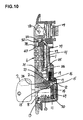
- Essential components of the combination lock 6 are: a plurality of the marked dial discs 4; a plurality of cam discs 41, each of which has a part thereof inserted into a center through-hole of the dial disc 4 and stacked together into a neat pile; the center pin 20, which assumes the same shape as that of a round bar and inserted into a center hole 42 of each of the cam discs 41; a compression coil spring 43 for urging downward such a neat pile consisting of both the dial discs 4 and the cam discs 41 toward the cylinder lock 13; and the lock plate 5, which is provided with a rectangular opening portion 44 (shown in Fig. 16) to receive therein a part of each of the dial discs 4.
- the center through-hole 40 (shown in Fig. 19) of the dial disc 4 is constructed of a small-diameter bore portion 40a; and a pair of large-diameter bore portions 40b and 40c, sandwiched in between which is the small-diameter bore portion 40a.
- a small-diameter sleeve portion 41a of the cam disc 41 which is inserted into the small-diameter bore portion 40a of the dial disc 4 from above, projects downward from the lower large-diameter bore portion 40c of the dial disc 4, as is clear from Fig.
- a large-diameter flange portion 41b of the cam disc 41 is received in the upper large-diameter bore portion 40b of the dial disc 4.
- the large-diameter flange portion 41b has its upper end surface abut against a lower end surface of the small-diameter sleeve portion 41 a of the upper adjacent cam disc 41.
- a part of the peripheral portion of the dial disc 4 projects forward through a laterally elongated slot 68 formed in a front surface of the door handle 2.
- a pair of diametrically opposed projection groups formed in a peripheral surface of a root portion of the small-diameter sleeve portion 41a of the cam disc 41 are a pair of diametrically opposed projection groups, each of which groups contains three piece of equally-spaced interlocking projections 45.
- formed in an inner peripheral surface of the small-diameter bore portion 40a of the dial disc 4 are ten piece of equally-spaced interlocking grooves 46 which correspond in number to the marks "1" to "10" provided in the outer peripheral surface of the dial disc 4.
- the dial disc 4 and the corresponding cam disc 41 are combined with each other through engagement established between the interlocking projections 45 of the cam disc 41 and the corresponding interlocking grooves 46 of the dial disc 4, as shown in Fig. 16.
- an outer peripheral portion of the large-diameter flange portion 41b of the cam disc 41 is partially cut off to form a pair of V-shaped notch portions 47 which are adjacent to each other to form a large-angle notch in appearance.
- the lock plate 5 is provided with a pair of V-shaped receiving grooves 48 in cross section. As shown in Fig. 13, these grooves 48 of the lock plate 5 are formed in a bridge portion between adjacent ones of the rectangular opening portions 44 of the lock plate 5 and correspond, in position and contour, to the V-shaped notch portions 47 of the cam disc 41.
- an upper support projection 49a and a lower support projection 49b are formed in an upper end portion and a lower end portion of the lock plate 5, respectively.
- the lock plate 5 has its support projections 49a, 49b oppositely disposed from its locking end portion 25.
- the upper support projection 49a is supported by an upright wall plate portion 50 of the back plate member 39.
- the lower support projection 49b is supported in a through-hole 52 (shown in dotted lines in Fig. 13) of a partition wall plate 51 which is fixedly mounted on the back plate member 39.
- the lock plate 5 is resiliently urged forward by means of a compression coil spring 53 to prevent its locking end portion 25 from abutting against the restriction portion 26 of the slider 21.
- the center pin 20 of the combination lock 6 has its upper and its lower end portion inserted into an upper pin hole 54 and a lower pin hole 55, respectively, wherein the upper pin hole 54 is formed in the upright wall plate portion 50 of the back plate member 39; and the lower pin hole 55 is formed in the partition wall plate 51.
- the compression coil spring 43 for urging downward both the dial discs 4 and the cam discs 41 is loosely mounted on the upper end portion of the center pin 20 and compressed between the uppermost one of the cam discs 41 and the upright wall plate portion 50, as is clear from Fig. 24.
- the slider 21 is constructed of a plate member and capable of sliding along the back plate 39.
- a plurality of inner guide projections 56 are formed in both a main body and a pair of opposite side portions of the back plate 39 to extend inside the back plate 39 to slidably guide the slider 21.
- a first spring support projection 57 is formed in the back plate 39, which cooperates with a second spring support projection 59 of the slider 21 to support the compression coil spring or second spring member 22 therebetween.
- the second spring member 22 is used to urge the slider 21 downward toward the receiver lever 16.
- the slider 21 is provided with a guide groove 58 which receives therein the guide projection 56 of the back plate 39.
- the first pivot 17 of the receiver lever 16 extends in parallel with the front surface of the door 30.
- the slider 21 is provided with an escape opening 60 for preventing both the compression coil spring 53 and the partition wall plate 51 from interfering with the slider 21 in operation.
- an L-shaped opening 61 is formed in the back plate 39 oppositely disposed from the slider 21.
- the center pin 20 of the combination lock 6 is provided with a flange portion 20a which abuts against the lowermost one of the cam discs 41.
- the reset lever 62 has its proximal end ring portion 63 rotatably mounted on the center pin 20 in a position between the flange portion 20a and the partition wall plate 51.
- a grip portion 64 of the reset lever 62 passes through a vertical portion 61 a of the L-shaped opening 61 of the back plate 39, as shown in Figs. 23 and 24.
- the cam discs 41 After turning each of the dial discs 4 in a normal or a reverse direction a desired number of times, the cam discs 41 have their interlocking projections 45 engaged with the corresponding interlocking grooves 46 of the dial discs 4 to determine a new combination of the marks of the dial discs 4, wherein such a new combination differs from the previous combination of the marks of the dial discs 4.
- each of the cam discs 41 there are formed a plurality of positioning grooves 65 at predetermined intervals.
- the number of these positioning grooves 65 of the cam disc 41 is the same as that of the marks of the dial disc 4.
- a third spring member 66 for keeping the dial discs 4 in their desired angular positions is fixedly mounted on the side wall portion of the back plate member 39 in a manner such that the third spring member 66 has its front end projections 67 resiliently engaged with the corresponding positioning grooves 65 of the cam discs 41.
- a conventional disc tumbler lock mechanism in which as shown in Fig. 4, an eccentric cam projection 69 formed in a rear end surface of the rotor 8 of the cylinder lock 13 is slidably received in a laterally elongated slot 70 formed in the proximal end portion of the stopping plate 11.
- the internal lock mechanism 10 there is a pin tumbler lock mechanism or the like which is capable of being employed in the door locking handle assembly of the present invention.
- the combination lock 6 is unlocked; the cylinder lock 13 is unlocked using the key 7; the combination lock 6 is incorporated in the door handle 2 together with the cylinder lock 13 in a manner such that these locks 6, 13 are disposed adjacent to each other in the longitudinal direction of the door handle 2; the receiver lever 16 pivoted to the base body 1 is controlled in motion by means of the lock plate 5; the stopper plate 11 which is engaged with and disengaged from the receiver lever 16 is mechanically interlocked with the rotor 8 of the cylinder lock 13 to make it possible to lock and unlock the door handle 2 to and from the base body 1, so that it is possible for the present invention to downsize the door locking handle assembly in thickness as a whole in a condition in which a large number of eligible keys 7 are provided in an easy manner; and it is possible for the control operator of the various instruments contained in the box or container to control a large number of the users or persons in various
- the door locking handle assembly of the present invention having the above construction, it is possible to prevent the receiver lever 16 from turning or moving toward its unlocked position by simply having the upper end portion 14 of the stopping plate 11 abut against the cam slope 18 of the receiver lever 16. Due to this, in the door locking handle assembly of the present invention, there is no need for a separate drive mechanism for driving the receiver lever 16. This makes it possible to reduce the number of the components or parts of the door locking handle assembly and therefore possible to simplify the assembly in construction.
Landscapes
- Lock And Its Accessories (AREA)
- Control Of Vending Devices And Auxiliary Devices For Vending Devices (AREA)
- Purses, Travelling Bags, Baskets, Or Suitcases (AREA)
- Supports Or Holders For Household Use (AREA)
Applications Claiming Priority (2)
| Application Number | Priority Date | Filing Date | Title |
|---|---|---|---|
| JP2001230989 | 2001-07-31 | ||
| JP2001230989 | 2001-07-31 |
Publications (3)
| Publication Number | Publication Date |
|---|---|
| EP1281825A2 true EP1281825A2 (de) | 2003-02-05 |
| EP1281825A3 EP1281825A3 (de) | 2004-01-21 |
| EP1281825B1 EP1281825B1 (de) | 2005-10-19 |
Family
ID=19063110
Family Applications (1)
| Application Number | Title | Priority Date | Filing Date |
|---|---|---|---|
| EP02255283A Expired - Lifetime EP1281825B1 (de) | 2001-07-31 | 2002-07-29 | Verrigelbare Türgriffvorrichtung mit inegriertem Kombinationsschloss |
Country Status (8)
| Country | Link |
|---|---|
| US (1) | US6516641B1 (de) |
| EP (1) | EP1281825B1 (de) |
| KR (1) | KR100413508B1 (de) |
| CN (1) | CN1400372A (de) |
| AT (1) | ATE307256T1 (de) |
| DE (1) | DE60206708T2 (de) |
| HK (1) | HK1054065B (de) |
| TW (1) | TW493032B (de) |
Cited By (1)
| Publication number | Priority date | Publication date | Assignee | Title |
|---|---|---|---|---|
| EP1329575A3 (de) * | 2002-01-21 | 2004-01-21 | Takigen Manufacturing Co., Ltd. | Verriegelbarer Türgriff mit eingebautem Kombinationsschloss |
Families Citing this family (31)
| Publication number | Priority date | Publication date | Assignee | Title |
|---|---|---|---|---|
| JP2002266528A (ja) | 2001-03-07 | 2002-09-18 | Takigen Mfg Co Ltd | 扉用ロックハンドル装置 |
| JP3628673B2 (ja) * | 2002-07-18 | 2005-03-16 | タキゲン製造株式会社 | 複合錠組込み型扉用ロックハンドル装置の取付構造 |
| US7091429B2 (en) * | 2003-12-22 | 2006-08-15 | Yale Security Inc. | Privacy keypad |
| US7984631B2 (en) * | 2003-12-22 | 2011-07-26 | Yale Security Inc. | Modular escutcheon |
| CA2555969C (en) * | 2004-02-03 | 2009-07-07 | Master Lock Company Llc | Combination deadbolt |
| USD525519S1 (en) | 2005-03-29 | 2006-07-25 | Master Lock Company | Lock dial |
| DE202007009513U1 (de) * | 2007-07-06 | 2007-09-27 | Emka Beschlagteile Gmbh & Co. Kg | Schwenkhebelverschluss mit elektrisch verriegelbarem Griffhebel |
| US8348308B2 (en) | 2008-12-19 | 2013-01-08 | Amesbury Group, Inc. | High security lock for door |
| US8939474B2 (en) | 2011-06-03 | 2015-01-27 | Amesbury Group, Inc. | Lock with sliding locking elements |
| US9428937B2 (en) | 2011-07-22 | 2016-08-30 | Amesbury Group, Inc. | Multi-point lock having sequentially-actuated locking elements |
| CA2820526A1 (en) | 2012-06-18 | 2013-12-18 | Amesbury Group, Inc. | Handle-actuated sliding door lock actuation assemblies |
| WO2014036151A2 (en) | 2012-08-31 | 2014-03-06 | Amesbury Group, Inc. | Passive door lock mechanisms |
| US9637957B2 (en) | 2012-11-06 | 2017-05-02 | Amesbury Group, Inc. | Automatically-extending remote door lock bolts |
| USD708924S1 (en) * | 2013-05-09 | 2014-07-15 | Trimark Corporation | Pull handle with integrated keypad |
| JP5886808B2 (ja) * | 2013-09-24 | 2016-03-16 | タキゲン製造株式会社 | 扉用ロックハンドル装置 |
| US10156087B2 (en) * | 2014-08-01 | 2018-12-18 | Sinox Co., Ltd. | Lockset |
| CA2964792A1 (en) | 2014-10-16 | 2016-04-21 | Amesbury Group, Inc. | Opposed hook sliding door lock |
| CN106979651B (zh) * | 2016-01-15 | 2022-06-10 | 冰山松洋生物科技(大连)有限公司 | 低温冰箱的门装置 |
| US10968661B2 (en) | 2016-08-17 | 2021-04-06 | Amesbury Group, Inc. | Locking system having an electronic deadbolt |
| US11203473B1 (en) * | 2017-04-14 | 2021-12-21 | David McGowan | Cooler device |
| US10662675B2 (en) | 2017-04-18 | 2020-05-26 | Amesbury Group, Inc. | Modular electronic deadbolt systems |
| US10808424B2 (en) | 2017-05-01 | 2020-10-20 | Amesbury Group, Inc. | Modular multi-point lock |
| US11066850B2 (en) | 2017-07-25 | 2021-07-20 | Amesbury Group, Inc | Access handle for sliding doors |
| CA3036398A1 (en) | 2018-03-12 | 2019-09-12 | Amesbury Group, Inc. | Electronic deadbolt systems |
| US11834866B2 (en) | 2018-11-06 | 2023-12-05 | Amesbury Group, Inc. | Flexible coupling for electronic deadbolt systems |
| US11661771B2 (en) | 2018-11-13 | 2023-05-30 | Amesbury Group, Inc. | Electronic drive for door locks |
| CN109812131B (zh) * | 2019-03-28 | 2023-11-28 | 中山市海诗蔓智能科技有限公司 | 内置开锁机构的锁把手 |
| CN113137125B (zh) * | 2020-01-17 | 2024-12-13 | 青岛海尔特种电冰柜有限公司 | 一种门把手及卧式冷柜 |
| CN114046099B (zh) * | 2021-11-08 | 2023-02-03 | 东联信息技术有限公司 | 一种机柜锁的开锁方法和上锁方法 |
| USD981208S1 (en) * | 2022-10-13 | 2023-03-21 | Lishui Tengxun Network Technology Co., Ltd. | Electronic keypad deadbolt |
| USD1051698S1 (en) * | 2023-02-01 | 2024-11-19 | Martin Lehmann Gmbh & Co. Kg | Lock |
Family Cites Families (16)
| Publication number | Priority date | Publication date | Assignee | Title |
|---|---|---|---|---|
| US1613550A (en) * | 1924-11-14 | 1927-01-04 | Sesamee Company | Keyless lock |
| US3107513A (en) * | 1958-04-28 | 1963-10-22 | James A Walston | Combination lock latch means |
| US3633388A (en) * | 1970-08-28 | 1972-01-11 | Long Mfg Co Inc | Combination lock construction |
| DE2850274A1 (de) * | 1978-11-20 | 1980-05-22 | Franzen Soehne S | Abschliessbarer betaetigungsgriff, insbesondere fuer fenster |
| US4557122A (en) * | 1983-08-25 | 1985-12-10 | Blake Hwang | Combined combination and key-type lock |
| GB8618489D0 (en) * | 1986-07-29 | 1986-09-03 | Knight R W | Window/door latch |
| DE3706723A1 (de) * | 1987-03-02 | 1988-09-15 | Pfeiffer Michael Design | Verriegelbarer, tragbarer behaelter, insbesondere reisekoffer, boardcase, aktenkoffer oder dergleichen |
| US4770013A (en) * | 1987-03-31 | 1988-09-13 | Clover Co., Ltd. | Combination lock |
| JPH0647888B2 (ja) * | 1987-09-02 | 1994-06-22 | 株式会社クローバー | 組合せ錠 |
| US4901545A (en) * | 1987-12-28 | 1990-02-20 | Rising Star Technologies (A Partnership) | Self-contained electromechanical locking device |
| US4914931A (en) * | 1988-11-16 | 1990-04-10 | Shu Shung Chung | Handle type combination lock for a suitcase |
| US5063764A (en) * | 1989-02-09 | 1991-11-12 | Convoy Security Company | Roll-up door lock |
| DE9004756U1 (de) * | 1990-04-27 | 1991-08-22 | Ramsauer, Dieter, 5620 Velbert | Mit Zylinderschloßeinrichtung arretierbarer Schwenkhebelverschluß |
| JPH0762416B2 (ja) * | 1993-02-22 | 1995-07-05 | タキゲン製造株式会社 | 引出し回転型扉用ロックハンドル装置 |
| US5692403A (en) * | 1996-07-08 | 1997-12-02 | Ling; Chong-Kuan | Doubly lockable belt locking device |
| US6378344B1 (en) * | 2000-09-18 | 2002-04-30 | Klaus W. Gartner | Combination lock handle |
-
2001
- 2001-12-19 TW TW090131437A patent/TW493032B/zh not_active IP Right Cessation
- 2001-12-24 KR KR10-2001-0083856A patent/KR100413508B1/ko not_active Expired - Fee Related
-
2002
- 2002-06-27 US US10/183,801 patent/US6516641B1/en not_active Expired - Lifetime
- 2002-07-29 DE DE60206708T patent/DE60206708T2/de not_active Expired - Lifetime
- 2002-07-29 AT AT02255283T patent/ATE307256T1/de not_active IP Right Cessation
- 2002-07-29 EP EP02255283A patent/EP1281825B1/de not_active Expired - Lifetime
- 2002-07-30 CN CN02127379A patent/CN1400372A/zh active Pending
-
2003
- 2003-07-07 HK HK03104819.8A patent/HK1054065B/en not_active IP Right Cessation
Cited By (1)
| Publication number | Priority date | Publication date | Assignee | Title |
|---|---|---|---|---|
| EP1329575A3 (de) * | 2002-01-21 | 2004-01-21 | Takigen Manufacturing Co., Ltd. | Verriegelbarer Türgriff mit eingebautem Kombinationsschloss |
Also Published As
| Publication number | Publication date |
|---|---|
| EP1281825A3 (de) | 2004-01-21 |
| EP1281825B1 (de) | 2005-10-19 |
| KR20030012784A (ko) | 2003-02-12 |
| DE60206708D1 (de) | 2006-03-02 |
| HK1054065A1 (en) | 2003-11-14 |
| US20030024286A1 (en) | 2003-02-06 |
| ATE307256T1 (de) | 2005-11-15 |
| CN1400372A (zh) | 2003-03-05 |
| DE60206708T2 (de) | 2006-06-29 |
| HK1054065B (en) | 2006-09-15 |
| KR100413508B1 (ko) | 2004-01-03 |
| TW493032B (en) | 2002-07-01 |
| US6516641B1 (en) | 2003-02-11 |
Similar Documents
| Publication | Publication Date | Title |
|---|---|---|
| EP1281825B1 (de) | Verrigelbare Türgriffvorrichtung mit inegriertem Kombinationsschloss | |
| US6955069B2 (en) | Door locking handle assembly with built-in combination lock | |
| US6694786B2 (en) | Door locking handle assembly with built-in combination lock | |
| US6722169B2 (en) | Door locking handle assembly | |
| US6550296B2 (en) | Door locking handle assembly with built-in combination lock | |
| US7100407B2 (en) | Handled lock set for a door | |
| US20070157679A1 (en) | Padlock | |
| US7213425B2 (en) | Padlock having dual unlocking modes | |
| US6546764B2 (en) | Door locking handle assembly of double lock type | |
| US7458239B1 (en) | Combination-changeable complex lock | |
| JPH0662150U (ja) | 引出し回転型扉用ロックハンドル装置 | |
| US6564598B2 (en) | Door locking handle assembly with built-in combination lock | |
| JP2003113682A (ja) | 複合錠組込み型扉用ロックハンドル装置 | |
| HK1050233A (en) | Door locking handle assembly | |
| JP4245901B2 (ja) | 防犯サムターン | |
| HK1053343B (en) | Door locking handle assembly with built-in combination lock | |
| JP4359461B2 (ja) | 防犯サムターン | |
| JP2008095501A (ja) | ロッカー用施錠装置 | |
| JPH07215356A (ja) | ロック付蓋体 |
Legal Events
| Date | Code | Title | Description |
|---|---|---|---|
| PUAI | Public reference made under article 153(3) epc to a published international application that has entered the european phase |
Free format text: ORIGINAL CODE: 0009012 |
|
| AK | Designated contracting states |
Designated state(s): AT BE BG CH CY CZ DE DK EE ES FI FR GB GR IE IT LI LU MC NL PT SE SK TR |
|
| AX | Request for extension of the european patent |
Extension state: AL LT LV MK RO SI |
|
| PUAL | Search report despatched |
Free format text: ORIGINAL CODE: 0009013 |
|
| AK | Designated contracting states |
Kind code of ref document: A3 Designated state(s): AT BE BG CH CY CZ DE DK EE ES FI FR GB GR IE IT LI LU MC NL PT SE SK TR |
|
| AX | Request for extension of the european patent |
Extension state: AL LT LV MK RO SI |
|
| RIC1 | Information provided on ipc code assigned before grant |
Ipc: 7E 05B 13/10 A Ipc: 7E 05B 1/00 B Ipc: 7E 05B 35/08 B Ipc: 7E 05B 37/02 B Ipc: 7E 05B 5/02 B |
|
| 17P | Request for examination filed |
Effective date: 20031216 |
|
| AKX | Designation fees paid |
Designated state(s): AT BE BG CH CY CZ DE DK EE ES FI FR GB GR IE IT LI LU MC NL PT SE SK TR |
|
| GRAP | Despatch of communication of intention to grant a patent |
Free format text: ORIGINAL CODE: EPIDOSNIGR1 |
|
| GRAS | Grant fee paid |
Free format text: ORIGINAL CODE: EPIDOSNIGR3 |
|
| GRAA | (expected) grant |
Free format text: ORIGINAL CODE: 0009210 |
|
| AK | Designated contracting states |
Kind code of ref document: B1 Designated state(s): AT BE BG CH CY CZ DE DK EE ES FI FR GB GR IE IT LI LU MC NL PT SE SK TR |
|
| PG25 | Lapsed in a contracting state [announced via postgrant information from national office to epo] |
Ref country code: CH Free format text: LAPSE BECAUSE OF FAILURE TO SUBMIT A TRANSLATION OF THE DESCRIPTION OR TO PAY THE FEE WITHIN THE PRESCRIBED TIME-LIMIT Effective date: 20051019 Ref country code: CZ Free format text: LAPSE BECAUSE OF FAILURE TO SUBMIT A TRANSLATION OF THE DESCRIPTION OR TO PAY THE FEE WITHIN THE PRESCRIBED TIME-LIMIT Effective date: 20051019 Ref country code: LI Free format text: LAPSE BECAUSE OF FAILURE TO SUBMIT A TRANSLATION OF THE DESCRIPTION OR TO PAY THE FEE WITHIN THE PRESCRIBED TIME-LIMIT Effective date: 20051019 Ref country code: FI Free format text: LAPSE BECAUSE OF FAILURE TO SUBMIT A TRANSLATION OF THE DESCRIPTION OR TO PAY THE FEE WITHIN THE PRESCRIBED TIME-LIMIT Effective date: 20051019 Ref country code: NL Free format text: LAPSE BECAUSE OF FAILURE TO SUBMIT A TRANSLATION OF THE DESCRIPTION OR TO PAY THE FEE WITHIN THE PRESCRIBED TIME-LIMIT Effective date: 20051019 Ref country code: AT Free format text: LAPSE BECAUSE OF FAILURE TO SUBMIT A TRANSLATION OF THE DESCRIPTION OR TO PAY THE FEE WITHIN THE PRESCRIBED TIME-LIMIT Effective date: 20051019 Ref country code: SK Free format text: LAPSE BECAUSE OF FAILURE TO SUBMIT A TRANSLATION OF THE DESCRIPTION OR TO PAY THE FEE WITHIN THE PRESCRIBED TIME-LIMIT Effective date: 20051019 Ref country code: BE Free format text: LAPSE BECAUSE OF FAILURE TO SUBMIT A TRANSLATION OF THE DESCRIPTION OR TO PAY THE FEE WITHIN THE PRESCRIBED TIME-LIMIT Effective date: 20051019 |
|
| REG | Reference to a national code |
Ref country code: GB Ref legal event code: FG4D |
|
| REG | Reference to a national code |
Ref country code: CH Ref legal event code: EP |
|
| REG | Reference to a national code |
Ref country code: IE Ref legal event code: FG4D |
|
| PG25 | Lapsed in a contracting state [announced via postgrant information from national office to epo] |
Ref country code: BG Free format text: LAPSE BECAUSE OF FAILURE TO SUBMIT A TRANSLATION OF THE DESCRIPTION OR TO PAY THE FEE WITHIN THE PRESCRIBED TIME-LIMIT Effective date: 20060119 Ref country code: GR Free format text: LAPSE BECAUSE OF FAILURE TO SUBMIT A TRANSLATION OF THE DESCRIPTION OR TO PAY THE FEE WITHIN THE PRESCRIBED TIME-LIMIT Effective date: 20060119 Ref country code: SE Free format text: LAPSE BECAUSE OF FAILURE TO SUBMIT A TRANSLATION OF THE DESCRIPTION OR TO PAY THE FEE WITHIN THE PRESCRIBED TIME-LIMIT Effective date: 20060119 Ref country code: DK Free format text: LAPSE BECAUSE OF FAILURE TO SUBMIT A TRANSLATION OF THE DESCRIPTION OR TO PAY THE FEE WITHIN THE PRESCRIBED TIME-LIMIT Effective date: 20060119 |
|
| PG25 | Lapsed in a contracting state [announced via postgrant information from national office to epo] |
Ref country code: ES Free format text: LAPSE BECAUSE OF FAILURE TO SUBMIT A TRANSLATION OF THE DESCRIPTION OR TO PAY THE FEE WITHIN THE PRESCRIBED TIME-LIMIT Effective date: 20060130 |
|
| REF | Corresponds to: |
Ref document number: 60206708 Country of ref document: DE Date of ref document: 20060302 Kind code of ref document: P |
|
| PG25 | Lapsed in a contracting state [announced via postgrant information from national office to epo] |
Ref country code: PT Free format text: LAPSE BECAUSE OF FAILURE TO SUBMIT A TRANSLATION OF THE DESCRIPTION OR TO PAY THE FEE WITHIN THE PRESCRIBED TIME-LIMIT Effective date: 20060320 |
|
| NLV1 | Nl: lapsed or annulled due to failure to fulfill the requirements of art. 29p and 29m of the patents act | ||
| REG | Reference to a national code |
Ref country code: CH Ref legal event code: PL |
|
| ET | Fr: translation filed | ||
| PG25 | Lapsed in a contracting state [announced via postgrant information from national office to epo] |
Ref country code: IE Free format text: LAPSE BECAUSE OF NON-PAYMENT OF DUE FEES Effective date: 20060731 Ref country code: MC Free format text: LAPSE BECAUSE OF NON-PAYMENT OF DUE FEES Effective date: 20060731 |
|
| PLBE | No opposition filed within time limit |
Free format text: ORIGINAL CODE: 0009261 |
|
| STAA | Information on the status of an ep patent application or granted ep patent |
Free format text: STATUS: NO OPPOSITION FILED WITHIN TIME LIMIT |
|
| REG | Reference to a national code |
Ref country code: HK Ref legal event code: GR Ref document number: 1054065 Country of ref document: HK |
|
| 26N | No opposition filed |
Effective date: 20060720 |
|
| REG | Reference to a national code |
Ref country code: IE Ref legal event code: MM4A |
|
| PG25 | Lapsed in a contracting state [announced via postgrant information from national office to epo] |
Ref country code: EE Free format text: LAPSE BECAUSE OF FAILURE TO SUBMIT A TRANSLATION OF THE DESCRIPTION OR TO PAY THE FEE WITHIN THE PRESCRIBED TIME-LIMIT Effective date: 20051019 |
|
| PG25 | Lapsed in a contracting state [announced via postgrant information from national office to epo] |
Ref country code: TR Free format text: LAPSE BECAUSE OF FAILURE TO SUBMIT A TRANSLATION OF THE DESCRIPTION OR TO PAY THE FEE WITHIN THE PRESCRIBED TIME-LIMIT Effective date: 20051019 Ref country code: LU Free format text: LAPSE BECAUSE OF NON-PAYMENT OF DUE FEES Effective date: 20060729 |
|
| PG25 | Lapsed in a contracting state [announced via postgrant information from national office to epo] |
Ref country code: CY Free format text: LAPSE BECAUSE OF FAILURE TO SUBMIT A TRANSLATION OF THE DESCRIPTION OR TO PAY THE FEE WITHIN THE PRESCRIBED TIME-LIMIT Effective date: 20051019 |
|
| PGFP | Annual fee paid to national office [announced via postgrant information from national office to epo] |
Ref country code: DE Payment date: 20130724 Year of fee payment: 12 |
|
| PGFP | Annual fee paid to national office [announced via postgrant information from national office to epo] |
Ref country code: FR Payment date: 20130724 Year of fee payment: 12 Ref country code: GB Payment date: 20130724 Year of fee payment: 12 |
|
| PGFP | Annual fee paid to national office [announced via postgrant information from national office to epo] |
Ref country code: IT Payment date: 20130712 Year of fee payment: 12 |
|
| REG | Reference to a national code |
Ref country code: DE Ref legal event code: R119 Ref document number: 60206708 Country of ref document: DE |
|
| GBPC | Gb: european patent ceased through non-payment of renewal fee |
Effective date: 20140729 |
|
| REG | Reference to a national code |
Ref country code: FR Ref legal event code: ST Effective date: 20150331 |
|
| PG25 | Lapsed in a contracting state [announced via postgrant information from national office to epo] |
Ref country code: IT Free format text: LAPSE BECAUSE OF NON-PAYMENT OF DUE FEES Effective date: 20140729 Ref country code: DE Free format text: LAPSE BECAUSE OF NON-PAYMENT OF DUE FEES Effective date: 20150203 |
|
| REG | Reference to a national code |
Ref country code: DE Ref legal event code: R119 Ref document number: 60206708 Country of ref document: DE Effective date: 20150203 |
|
| PG25 | Lapsed in a contracting state [announced via postgrant information from national office to epo] |
Ref country code: FR Free format text: LAPSE BECAUSE OF NON-PAYMENT OF DUE FEES Effective date: 20140731 Ref country code: GB Free format text: LAPSE BECAUSE OF NON-PAYMENT OF DUE FEES Effective date: 20140729 |