EP1281845A2 - Soupape de commande additionnelle dans le conduit d'admission d'un moteur à combustion interne - Google Patents
Soupape de commande additionnelle dans le conduit d'admission d'un moteur à combustion interne Download PDFInfo
- Publication number
- EP1281845A2 EP1281845A2 EP02015862A EP02015862A EP1281845A2 EP 1281845 A2 EP1281845 A2 EP 1281845A2 EP 02015862 A EP02015862 A EP 02015862A EP 02015862 A EP02015862 A EP 02015862A EP 1281845 A2 EP1281845 A2 EP 1281845A2
- Authority
- EP
- European Patent Office
- Prior art keywords
- flow
- control valve
- valve device
- hat
- valve member
- Prior art date
- Legal status (The legal status is an assumption and is not a legal conclusion. Google has not performed a legal analysis and makes no representation as to the accuracy of the status listed.)
- Granted
Links
- 238000002485 combustion reaction Methods 0.000 title claims description 15
- 238000011144 upstream manufacturing Methods 0.000 claims description 5
- 239000000463 material Substances 0.000 claims description 3
- 230000008859 change Effects 0.000 claims description 2
- 238000010278 pulse charging Methods 0.000 description 7
- 230000008901 benefit Effects 0.000 description 3
- 230000002349 favourable effect Effects 0.000 description 3
- 239000000696 magnetic material Substances 0.000 description 3
- 230000003534 oscillatory effect Effects 0.000 description 3
- 238000007789 sealing Methods 0.000 description 3
- 230000015572 biosynthetic process Effects 0.000 description 2
- 230000009849 deactivation Effects 0.000 description 2
- 230000009471 action Effects 0.000 description 1
- 230000004913 activation Effects 0.000 description 1
- 239000002131 composite material Substances 0.000 description 1
- 238000011161 development Methods 0.000 description 1
- 230000018109 developmental process Effects 0.000 description 1
- 238000006073 displacement reaction Methods 0.000 description 1
- 238000005265 energy consumption Methods 0.000 description 1
- 230000005284 excitation Effects 0.000 description 1
- 238000004519 manufacturing process Methods 0.000 description 1
- 239000000203 mixture Substances 0.000 description 1
- 238000002360 preparation method Methods 0.000 description 1
- 230000003584 silencer Effects 0.000 description 1
- 230000008719 thickening Effects 0.000 description 1
Images


Classifications
-
- F—MECHANICAL ENGINEERING; LIGHTING; HEATING; WEAPONS; BLASTING
- F02—COMBUSTION ENGINES; HOT-GAS OR COMBUSTION-PRODUCT ENGINE PLANTS
- F02D—CONTROLLING COMBUSTION ENGINES
- F02D9/00—Controlling engines by throttling air or fuel-and-air induction conduits or exhaust conduits
- F02D9/08—Throttle valves specially adapted therefor; Arrangements of such valves in conduits
- F02D9/12—Throttle valves specially adapted therefor; Arrangements of such valves in conduits having slidably-mounted valve members; having valve members movable longitudinally of conduit
-
- F—MECHANICAL ENGINEERING; LIGHTING; HEATING; WEAPONS; BLASTING
- F02—COMBUSTION ENGINES; HOT-GAS OR COMBUSTION-PRODUCT ENGINE PLANTS
- F02B—INTERNAL-COMBUSTION PISTON ENGINES; COMBUSTION ENGINES IN GENERAL
- F02B29/00—Engines characterised by provision for charging or scavenging not provided for in groups F02B25/00, F02B27/00 or F02B33/00 - F02B39/00; Details thereof
- F02B29/02—Other fluid-dynamic features of induction systems for improving quantity of charge
-
- F—MECHANICAL ENGINEERING; LIGHTING; HEATING; WEAPONS; BLASTING
- F02—COMBUSTION ENGINES; HOT-GAS OR COMBUSTION-PRODUCT ENGINE PLANTS
- F02B—INTERNAL-COMBUSTION PISTON ENGINES; COMBUSTION ENGINES IN GENERAL
- F02B29/00—Engines characterised by provision for charging or scavenging not provided for in groups F02B25/00, F02B27/00 or F02B33/00 - F02B39/00; Details thereof
- F02B29/08—Modifying distribution valve timing for charging purposes
- F02B29/083—Cyclically operated valves disposed upstream of the cylinder intake valve, controlled by external means
-
- Y—GENERAL TAGGING OF NEW TECHNOLOGICAL DEVELOPMENTS; GENERAL TAGGING OF CROSS-SECTIONAL TECHNOLOGIES SPANNING OVER SEVERAL SECTIONS OF THE IPC; TECHNICAL SUBJECTS COVERED BY FORMER USPC CROSS-REFERENCE ART COLLECTIONS [XRACs] AND DIGESTS
- Y02—TECHNOLOGIES OR APPLICATIONS FOR MITIGATION OR ADAPTATION AGAINST CLIMATE CHANGE
- Y02T—CLIMATE CHANGE MITIGATION TECHNOLOGIES RELATED TO TRANSPORTATION
- Y02T10/00—Road transport of goods or passengers
- Y02T10/10—Internal combustion engine [ICE] based vehicles
- Y02T10/12—Improving ICE efficiencies
Definitions
- the invention relates to one arranged in an inlet duct of a piston internal combustion engine Additional control valve device.
- valve member is, for example a sealing body which is triangular in cross section and which is connected via a shaft to a bracket provided in the inlet duct is movably guided. It can only be operated by differential pressure or for example by means of an actuator, for example a servo motor.
- the actuator can have a mechanical linkage that extends from the outside into the inlet duct protrudes.
- the valve member can be designed as a truncated cone, the flattened tip has moved in.
- the valve member can be actuated by means of an electromagnet or a gas spring become.
- a peculiarity of the valves according to the aforementioned document is that they are too significant vortex formation and the flow resistance of the flow through the inlet channel enlarge.
- DE 611 659 C1 shows a streamlined arrangement arranged in a silencer Rotary body, through the total displacement of which the average cross-section of an annular gap is changeable.
- the invention has for its object one in an inlet channel of a piston internal combustion engine arranged additional control valve device to create, with the simple structure the demands made in practice with regard to low influence on the flow resistance and quicker and operable with little energy consumption be fulfilled.
- the additional control valve causes practically no increase in flow resistance of the inlet channel, since the surface of the valve member is in its open position runs flush with the remaining surface of the flow body.
- the flow body is further developed in an advantageous manner.
- the additional control valve device in can be accommodated in a simple manner in the inlet duct, with actuation of the valve member only an electrical or possibly pneumatic or hydraulic connection to the Flow body is required.
- Claims 5 to 12 characterize advantageous embodiments and developments of the additional control valve device according to the invention.
- the additional control valve device according to the invention can be used both for pulse charging will also be designed in such a way that gasoline engines can operate without a throttle valve is possible. Furthermore, additional degrees of freedom are available with the additional control valve device given with regard to other types of charge control.
- a reciprocating piston internal combustion engine has a plurality of cylinders 2, in each of which one Piston 4 works, which is connected to a crankshaft 8 via a connecting rod 6.
- the fresh air or fresh charge supply to the cylinder 2 takes place through an air filter 10 which a supply line 12 is connected to an air collector 14, from which individual, each lead oscillating tubes forming an inlet channel 16 into the combustion chamber 18 of the cylinder 2.
- an inlet valve 20 In the opening of each vibrating tube or inlet duct 16 into the combustion chamber 18 is at least an inlet valve 20 is arranged.
- In the opening of the combustion chamber into an outlet duct 22 works at least one exhaust valve 24.
- the formation of the intake system with oscillating tubes is advantageous but not mandatory.
- An additional control valve device is located in the inlet channel 16 upstream of the inlet valve 20 26 is provided, the additional control valve of which is controlled by a control unit 28.
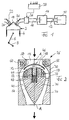
- FIG. 2 shows a longitudinal section through the additional control valve device 26 of FIG. 1.
- the through Arrows illustrating the air or fresh charge flow direction is from top to bottom in FIG. 2.
- the inlet channel 16 widens at the upstream end of the additional control valve device 26 by making the inner wall of the inlet duct body 30 conical expanding region 32.
- the extension area 32 goes in over a widest point a tapered area 34, which eventually smooth in the not shown to Inlet valve leading part of the inlet channel 16 passes.
- the flow body 36 is designed in accordance with the inner wall of the inlet channel body 30, so that an annular gap 40 with an annular gap between it and the inlet channel body 30 Flow cross section is formed.
- the flow cross section of the annular gap can be in the flow direction , as is known in hydraulic or aerodynamic devices, initially decrease and then slowly increase again.
- the flow body 36 has a blind hole 42 which is coaxial is formed with the axis A-A of the flow or the entire arrangement.
- the shaft 44 of an overall mushroom-shaped valve member 46 is guided in a blind hole, the hat 48 of the valve member 24 attached to the stem 44 shaped and the contours of the extension area 32 and the flow body 36 are adapted to it that the hat 48 in an upper, closed position according to FIG. 2, sealing on an inner valve seat 50 forming area of the extension area 32 and is flush in a lower open position runs with the outer contour of the flow body 36, which correspondingly excluded the hat 48 is.
- the hat 48 is on the side facing away from the inlet valve 20 convex with a vertex in the A-A axis.
- the shaft 44 ends in a collar 52. Between the collar 52 and the bottom of the blind hole 42 a first spring 54 is supported. Between the collar 52 and one at the top of the Blind spring 42 formed collar is supported by a further spring 56. That way it forms the valve member 46 together with the two springs 54 and 56 form an oscillatory system, which is held in a middle position by the springs.
- the natural frequency of the vibratory System is given by the spring constants and the weight of the valve member 46.
- the flow body 36 as a whole is for the ability to mount the valve member and the springs constructed in two parts, the upper part and the lower part with each other in any suitable manner are connectable.
- An annular electromagnet 58 is arranged in the upper part of the flow body 36 Pole surface is exposed and interacts with the hat 48 made of magnetic material.
- a further ring magnet 60 is located in the inlet channel body 30 in the region of the valve seat 50 arranged, the pole face also cooperates with the hat 48.
- the valve member 46 with the hat 48 When the ring magnet 58 is excited, the valve member 46 with the hat 48, if necessary supported by the air flow from the center position shown against the force of the spring 54 pulled into the open position, in which the hat 48 on the pole face of the ring magnet 58 is applied. If the ring magnet 58 is deactivated, the valve member oscillates under the influence of the Springs 54 and 56 in the direction of the closed position, in which there is a coordinated excitation of the Ring magnet 60 is held against the valve seat 50 by abutment of the hat 48. Will the magnet 60 deactivated, the valve member moves into the open position by the force of the springs, in which it is held by means of the magnet 58, etc.
- the natural frequency of the vibratable System is advantageously higher than the frequency with which the valve is actuated must, so that an extremely quick change between open and closed position is possible is, with only the holding force of the magnets and the kinetic Energy is stored in the springs.
- the respective contact surfaces can be designed accordingly, so that each time the system an air cushion has to be displaced.
- the auxiliary control valve When used for pulse charging for high torque even at low speeds the auxiliary control valve remains closed during the intake stroke with the intake valve open and is opened with the inlet valve still open when a high vacuum builds up Has. Fresh charge flows into the combustion chamber with high energy and correspondingly good filling, whose inlet valve is closed before backflow occurs. The additional valve is closed and is available for a new intake cycle. If the throttle valve is missing the additional control valve is actuated in coordination with the inlet valve such that only a predetermined small amount of fresh charge reaches the combustion chamber during an intake stroke.
- the angle that the valve seat forms with the central axis is on the seal and the flow matched and is for example at 45 °.
- the two ring magnets 58 and 60 have approximately the same radial Have diameters so that their pole faces are roughly opposite. It will be short Field lines are achieved in the anchor and a low anchor mass is possible. Through the nozzle or Diffuser flow in the annular gap 40 can be a targeted speed increase or deceleration can be achieved, which results in minimal flow losses.
- FIG. 3 shows an embodiment of an additional control valve device modified compared to FIG. 2 26, in which the collar 52 of the embodiment according to FIG. 2 is expanded to form an anchor plate 62 and the ring magnets 58 and 60 are received within the flow body 36. Otherwise, the function of the embodiment according to FIG. 3 corresponds to that of FIG. 2. Since the 3 does not define the closed position of the valve member 46 is that the hat 48 is held in direct contact with the valve seat 50 by magnetic force, but because the armature plate 62 is held by the ring magnet 60, it is advantageous to compensate for tolerances to make the hat 48 somewhat more elastic, which in turn it is possible that the hat 48 does not have to be made of magnetic material.
- the same advantages are achieved with the embodiment according to FIG. 3 as with that of FIG. 2. Because the angle of the valve seat 50 defines the angle at which the fresh charge flows into the annular gap 40, not be matched to magnetic holding forces must, but can mainly be determined from a flow point of view, the Angles should be slightly larger and be 50 degrees.
- FIG. 4 shows an embodiment of the additional control valve device which is modified compared to FIG. 3 26, the features of the embodiment according to FIG. 3 combined with those of FIG. 2 by in addition to the ring magnets 58 and 60 of FIG. 3 in the area of the valve seat 50 in the inlet channel body 30 an additional ring magnet 62 is arranged, which in this case also hat 48 consisting at least partially of magnetizable material directly in contact urges the valve seat 50.
- the ring magnet 60 serves to capture and hold the anchor plate 62 in the closed position.
- the additional ring magnet 62 is used to capture and hold the hat 48 in sealing system on valve seat 50.
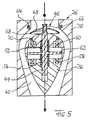
- Fig. 5 shows a further embodiment of an additional valve device, which compared to the Fig. 3 is modified.
- the hat 48 is movably guided on the shaft 44 and is made of two springs 66 and 68, which are opposed between the hat 48 and the Support shaft 44 pretensioned in a central position so that the hat with the springs is opposite the shaft forms an oscillatory system.
- a ring magnet 64 is arranged in the inlet channel body 30.
- Another ring magnet 70 is arranged in the flow body 36.
- the ring magnets 64 and 70 preferably form pure holding magnets for holding the hat 48 in its open or closed position while the magnets 58 and 60 form catch magnets for the anchor plate 62.
- the magnets 64 and 70 can be dimensioned weaker.
- the advantage becomes shorter Switching times between open and closed position of the valve achieved. Assume that The valve is in the closed position, i.e. the hat 48 in contact with the excited ring magnet 64 and the armature plate 62 in contact with the excited ring magnet 60. When the valve is then switched should be deactivated, the magnet 60 is deactivated and the magnet 58 is activated, so that the Anchor plate 62 moves under the action of springs 52, 54 in contact with the ring magnet 58 and is held there.
- the holding magnet 64 initially remains excited, so that the hat 48 in the closed position remains, whereby the shaft 44 deforms relative to the hat 48 while the springs 66, 68 are deformed gem. Fig. 5 moved down. If the magnet 64 then, for example, just before the anchor plate reaches its lower position, deactivated, that of the springs 66 and 68 moves biased hat 48 accelerates into contact with the magnet 70 and is in the open position held.
- the effective switching time of the valve which is given by the time period by the Hat to move from the closed to the open position and vice versa is shortened, which reduces charge exchange losses and enables more precise control is.
- the additional control valve device described can be modified in a variety of ways:
- Fig. 5 as well the holding magnet 64 of FIG. 4 can be formed by permanent magnets whose strength is based on the springs and the catch magnets are matched so that the holding magnets the movement of the Release hats 48 in a suitable manner.
- the valve member does not necessarily have to be a component of an oscillatory system.
- the valve member can be actuated hydraulically, pneumatically or in some other way, for example by holding the brackets 38 (FIG. 2) corresponding supply lines have been made.
- the bottom of the blind hole 42 can in be vented in a variety of ways and the shaft can correspond to the blind hole stepped cross sections can be formed so that the movement of the valve member in can dampen in various ways before reaching the open or closed position.
- the 5 can also be used without the magnets 64 and 70 for tolerance compensation become.
Landscapes
- Engineering & Computer Science (AREA)
- Chemical & Material Sciences (AREA)
- Combustion & Propulsion (AREA)
- Mechanical Engineering (AREA)
- General Engineering & Computer Science (AREA)
- Magnetically Actuated Valves (AREA)
- Characterised By The Charging Evacuation (AREA)
- Lift Valve (AREA)
Applications Claiming Priority (2)
| Application Number | Priority Date | Filing Date | Title |
|---|---|---|---|
| DE10137828A DE10137828B4 (de) | 2001-08-02 | 2001-08-02 | In einem Einlasskanal einer Kolbenbrennkraftmaschine angeordnete Zusatzsteuerventileinrichtung |
| DE10137828 | 2001-08-02 |
Publications (3)
| Publication Number | Publication Date |
|---|---|
| EP1281845A2 true EP1281845A2 (fr) | 2003-02-05 |
| EP1281845A3 EP1281845A3 (fr) | 2004-01-07 |
| EP1281845B1 EP1281845B1 (fr) | 2007-02-21 |
Family
ID=7694086
Family Applications (1)
| Application Number | Title | Priority Date | Filing Date |
|---|---|---|---|
| EP02015862A Expired - Lifetime EP1281845B1 (fr) | 2001-08-02 | 2002-07-16 | Soupape de commande additionnelle dans le conduit d'admission d'un moteur à combustion interne |
Country Status (4)
| Country | Link |
|---|---|
| US (1) | US6637405B2 (fr) |
| EP (1) | EP1281845B1 (fr) |
| AT (1) | ATE354723T1 (fr) |
| DE (2) | DE10137828B4 (fr) |
Cited By (2)
| Publication number | Priority date | Publication date | Assignee | Title |
|---|---|---|---|---|
| WO2010057726A1 (fr) * | 2008-11-21 | 2010-05-27 | Robert Bosch Gmbh | Module d'amenée de gaz |
| WO2012052260A1 (fr) * | 2010-10-18 | 2012-04-26 | Robert Bosch Gmbh | Dispositif d'étranglement |
Families Citing this family (20)
| Publication number | Priority date | Publication date | Assignee | Title |
|---|---|---|---|---|
| DE10207658B4 (de) * | 2002-02-22 | 2008-09-04 | Meta Motoren- Und Energie-Technik Gmbh | Verfahren zum Verkürzen der Öffnungs- und Schließflanke eines Ventils, sowie Ventil |
| US7004120B2 (en) * | 2003-05-09 | 2006-02-28 | Warren James C | Opposed piston engine |
| US6969048B2 (en) | 2003-06-17 | 2005-11-29 | Siemens Aktiengesellschaft | Valve element for supplementary control valve device |
| DE10327271A1 (de) * | 2003-06-17 | 2005-02-24 | Siemens Ag | Ventilglied für eine Zusatzsteuerventileinrichtung |
| DE10329400A1 (de) | 2003-06-30 | 2005-02-03 | Siemens Ag | Zusatzsteuerventileinrichtung für einen Einlasskanal einer Kolbenbrennkraftmaschine |
| DE10331689B4 (de) * | 2003-07-14 | 2010-04-22 | Audi Ag | Luftansaugkanal |
| DE10332440A1 (de) * | 2003-07-16 | 2005-02-17 | Siemens Ag | Zusatzsteuerventileinrichtung für einen Einlasskanal einer Kolbenbrennkraftmaschine |
| DE10335121A1 (de) * | 2003-07-31 | 2005-02-24 | Siemens Ag | Verfahren zur Anordnung eines Ventilgliedes in einer Zusatzsteuerventileinrichtung |
| DE10335136A1 (de) | 2003-07-31 | 2005-02-17 | Siemens Ag | Teileinheit für eine Zusatzsteuerventileinrichtung für einen Einlasskanal einer Kolbenbrennkraftmaschine |
| DE10335128A1 (de) * | 2003-07-31 | 2005-02-24 | Siemens Ag | Verfahren zur Herstellung eines Ventiltellers eines Ventilgliedes einer Zusatzsteuerventileinrichtung |
| DE10346005B4 (de) | 2003-10-02 | 2006-04-13 | Siemens Ag | Luftansaugmodul für eine Brennkraftmaschine mit Impulsaufladung |
| DE10347444B4 (de) * | 2003-10-13 | 2014-10-30 | Audi Ag | Vorrichtung zur Impulsaufladung |
| DE102005039368B9 (de) | 2005-08-08 | 2007-11-08 | Meta Motoren- Und Energie-Technik Gmbh | Schaltbarer Ventilbetätigungsmechanismus |
| DE102005052423B4 (de) * | 2005-11-03 | 2016-12-29 | Robert Bosch Gmbh | Vorrichtung zur Impulsaufladung einer Brennkraftmaschine |
| US7513235B2 (en) * | 2006-02-13 | 2009-04-07 | Gm Global Technology Operations, Inc. | Method and apparatus for operating impulse charger for transient torque management |
| DE102006023853A1 (de) * | 2006-05-19 | 2007-11-22 | Mahle International Gmbh | Verfahren zum Steuern einer Brennkraftmaschine |
| JP2009144699A (ja) * | 2007-12-14 | 2009-07-02 | Hyundai Motor Co Ltd | 車エンジン用インパルスチャージャー |
| ATE535692T1 (de) * | 2007-12-21 | 2011-12-15 | Hong Kong Meta Company Ltd | Verfahren zum betreiben einer brennkraftmaschine sowie brennkraftmaschine |
| WO2015092451A1 (fr) * | 2013-12-20 | 2015-06-25 | Pakai Tibor | Dispositif et procédé pour améliorer l'efficacité des moteurs à combustion interne |
| WO2019169365A1 (fr) * | 2018-03-02 | 2019-09-06 | S.P.M. Flow Control, Inc. | Nouvelle vanne ayant une surface d'étanchéité sphérique |
Citations (3)
| Publication number | Priority date | Publication date | Assignee | Title |
|---|---|---|---|---|
| DE611659C (de) | 1935-04-02 | Johannes Woerner | Schalldaempfer fuer Brennkraftmaschinen, bei welchem der Querschnitt des Austrittes der Abgase veraenderlich ist | |
| DE4314809A1 (de) | 1993-05-05 | 1994-11-10 | Freudenberg Carl Fa | Ansaugrohr für eine Verbrennungskraftmaschine |
| DE19908435A1 (de) | 1999-02-26 | 2000-09-07 | Meta Motoren Energietech | Verfahren und Vorrichtung zur Impulsaufladung einer Kolbenbrennkraftmaschine |
Family Cites Families (7)
| Publication number | Priority date | Publication date | Assignee | Title |
|---|---|---|---|---|
| GB430164A (en) * | 1933-12-09 | 1935-06-11 | Harold Henry Platts | Improvements in fluid operated streamline valves for flow or pressure control |
| FR1015012A (fr) * | 1949-03-29 | 1952-08-26 | Procédé et dispositif pour le réglage de fluides dans des conduites | |
| US2809660A (en) * | 1956-04-24 | 1957-10-15 | Aeroquip Corp | Cushioned streamlined check valve |
| US3119405A (en) * | 1961-06-12 | 1964-01-28 | Rotax Ltd | Compressed air or other gas control valves |
| US4412517A (en) * | 1980-10-06 | 1983-11-01 | Toyota Jidosha Kogyo Kabushiki Kaisha | Idling speed control device of an internal combustion engine |
| US5415142A (en) * | 1993-02-23 | 1995-05-16 | Mitsubishi Denki Kabushiki Kaisha | Control method and apparatus for internal combustion engine |
| US5666913A (en) * | 1996-05-29 | 1997-09-16 | Cummins Engine Company, Inc. | Variable timing cam follower lever assembly |
-
2001
- 2001-08-02 DE DE10137828A patent/DE10137828B4/de not_active Expired - Fee Related
-
2002
- 2002-07-16 DE DE50209519T patent/DE50209519D1/de not_active Expired - Lifetime
- 2002-07-16 AT AT02015862T patent/ATE354723T1/de not_active IP Right Cessation
- 2002-07-16 EP EP02015862A patent/EP1281845B1/fr not_active Expired - Lifetime
- 2002-08-02 US US10/212,372 patent/US6637405B2/en not_active Expired - Fee Related
Patent Citations (3)
| Publication number | Priority date | Publication date | Assignee | Title |
|---|---|---|---|---|
| DE611659C (de) | 1935-04-02 | Johannes Woerner | Schalldaempfer fuer Brennkraftmaschinen, bei welchem der Querschnitt des Austrittes der Abgase veraenderlich ist | |
| DE4314809A1 (de) | 1993-05-05 | 1994-11-10 | Freudenberg Carl Fa | Ansaugrohr für eine Verbrennungskraftmaschine |
| DE19908435A1 (de) | 1999-02-26 | 2000-09-07 | Meta Motoren Energietech | Verfahren und Vorrichtung zur Impulsaufladung einer Kolbenbrennkraftmaschine |
Cited By (2)
| Publication number | Priority date | Publication date | Assignee | Title |
|---|---|---|---|---|
| WO2010057726A1 (fr) * | 2008-11-21 | 2010-05-27 | Robert Bosch Gmbh | Module d'amenée de gaz |
| WO2012052260A1 (fr) * | 2010-10-18 | 2012-04-26 | Robert Bosch Gmbh | Dispositif d'étranglement |
Also Published As
| Publication number | Publication date |
|---|---|
| DE10137828A1 (de) | 2003-02-20 |
| US6637405B2 (en) | 2003-10-28 |
| DE50209519D1 (de) | 2007-04-05 |
| EP1281845B1 (fr) | 2007-02-21 |
| DE10137828B4 (de) | 2005-12-15 |
| US20030024502A1 (en) | 2003-02-06 |
| ATE354723T1 (de) | 2007-03-15 |
| EP1281845A3 (fr) | 2004-01-07 |
Similar Documents
| Publication | Publication Date | Title |
|---|---|---|
| DE10137828B4 (de) | In einem Einlasskanal einer Kolbenbrennkraftmaschine angeordnete Zusatzsteuerventileinrichtung | |
| EP1001143B1 (fr) | Commande de soupape pour soupapes d'admission et d'échappement de moteur à combustion interne | |
| EP1031712B1 (fr) | Dispositif d'alimentation par impulsions pour moteur à piston | |
| EP2394049B1 (fr) | Injecteur de carburant pour moteurs à combustion interne | |
| EP1762712B1 (fr) | Soupape de dérivation pour moteurs à combustion interne | |
| DE19610468B4 (de) | Verfahren zur lastabhängigen Steuerung der Gaswechselventile an einer Kolbenbrennkraftmaschine | |
| EP2151569B1 (fr) | Dispositif d'extraction d'un flux partiel de gaz d'échappement et moteur à combustion interne en étant équipé | |
| DE10215030B4 (de) | Ventilstellantrieb mit luftgedämpftem Kolben | |
| EP3455477B1 (fr) | Turbine pour une turbocompresseur avec un carter deux volutes et agencement de vanne pour la connection des deux volutes et contrôle de vanne de décharge | |
| EP0675281A1 (fr) | Soupape d'injection pour moteur, particulierement pour moteur diesel | |
| DE102020203194A1 (de) | Verbrennungskraftmaschine für den betrieb mit gasförmigem kraftstoff, insbesondere wasserstoff, und hochdruckventil zum einbringen von gasförmigem kraftstoff in die verbrennungskraftmaschine | |
| WO2000029734A1 (fr) | Moteur a combustion interne alternatif a commande de circuit de charge sans etranglement, comportant un dispositif pour produire une depression et procede d'exploitation dudit dispositif | |
| DE3318136A1 (de) | Ladevorrichtung zum aufladen von verbrennungsmotoren | |
| DE4314809B4 (de) | Ansaugrohr für eine Verbrennungskraftmaschine | |
| DE10207658B4 (de) | Verfahren zum Verkürzen der Öffnungs- und Schließflanke eines Ventils, sowie Ventil | |
| EP1881173A1 (fr) | Diffuseur pour un moteur à combustion interne et moteur à combustion interne avec diffuseur | |
| DE19826355A1 (de) | Vorrichtung und Verfahren zur Steuerung einer Abgasturboladerturbine | |
| DE10246182B3 (de) | In einem Einlasskanal einer Kolbenbrennkraftmaschine angeordnete Zusatzsteuerventileinrichtung | |
| DE202005021914U1 (de) | Turbinenstromregelventilsystem | |
| DE10141431A1 (de) | Kolbenbrennkraftmaschine mit druckentlastbaren Gasauslaßventilen | |
| DE102011104217A1 (de) | Schaltbare Strahlpumpe | |
| EP0624724B1 (fr) | Dispositif pour contrÔler la vitesse ralenti d'un moteur à combustion interne | |
| DE19602474A1 (de) | Einspritzzeitpunkt-Steuervorrichtung für eine Kraftstoffeinspritzpumpe | |
| DE10231968A1 (de) | Absperr- oder Drosselventil mit drehbarer Ventilklappe | |
| WO2011101087A1 (fr) | Procédé permettant de faire fonctionner un moteur à combustion interne à turbocompresseur à gaz d'échappement et moteur à combustion interne |
Legal Events
| Date | Code | Title | Description |
|---|---|---|---|
| PUAI | Public reference made under article 153(3) epc to a published international application that has entered the european phase |
Free format text: ORIGINAL CODE: 0009012 |
|
| AK | Designated contracting states |
Designated state(s): AT BE BG CH CY CZ DE DK EE ES FI FR GB GR IE IT LI LU MC NL PT SE SK TR |
|
| AX | Request for extension of the european patent |
Extension state: AL LT LV MK RO SI |
|
| PUAL | Search report despatched |
Free format text: ORIGINAL CODE: 0009013 |
|
| AK | Designated contracting states |
Kind code of ref document: A3 Designated state(s): AT BE BG CH CY CZ DE DK EE ES FI FR GB GR IE IT LI LU MC NL PT SE SK TR |
|
| AX | Request for extension of the european patent |
Extension state: AL LT LV MK RO SI |
|
| RIC1 | Information provided on ipc code assigned before grant |
Ipc: 7F 16K 1/12 B Ipc: 7F 02B 29/02 A Ipc: 7F 02B 27/02 B Ipc: 7F 02D 9/08 B |
|
| 17P | Request for examination filed |
Effective date: 20040707 |
|
| AKX | Designation fees paid |
Designated state(s): AT BE BG CH CY CZ DE DK EE ES FI FR GB GR IE IT LI LU MC NL PT SE SK TR |
|
| GRAP | Despatch of communication of intention to grant a patent |
Free format text: ORIGINAL CODE: EPIDOSNIGR1 |
|
| GRAS | Grant fee paid |
Free format text: ORIGINAL CODE: EPIDOSNIGR3 |
|
| GRAA | (expected) grant |
Free format text: ORIGINAL CODE: 0009210 |
|
| AK | Designated contracting states |
Kind code of ref document: B1 Designated state(s): AT BE BG CH CY CZ DE DK EE ES FI FR GB GR IE IT LI LU MC NL PT SE SK TR |
|
| PG25 | Lapsed in a contracting state [announced via postgrant information from national office to epo] |
Ref country code: IE Free format text: LAPSE BECAUSE OF FAILURE TO SUBMIT A TRANSLATION OF THE DESCRIPTION OR TO PAY THE FEE WITHIN THE PRESCRIBED TIME-LIMIT Effective date: 20070221 Ref country code: FI Free format text: LAPSE BECAUSE OF FAILURE TO SUBMIT A TRANSLATION OF THE DESCRIPTION OR TO PAY THE FEE WITHIN THE PRESCRIBED TIME-LIMIT Effective date: 20070221 Ref country code: DK Free format text: LAPSE BECAUSE OF FAILURE TO SUBMIT A TRANSLATION OF THE DESCRIPTION OR TO PAY THE FEE WITHIN THE PRESCRIBED TIME-LIMIT Effective date: 20070221 Ref country code: NL Free format text: LAPSE BECAUSE OF FAILURE TO SUBMIT A TRANSLATION OF THE DESCRIPTION OR TO PAY THE FEE WITHIN THE PRESCRIBED TIME-LIMIT Effective date: 20070221 |
|
| REG | Reference to a national code |
Ref country code: GB Ref legal event code: FG4D Free format text: NOT ENGLISH |
|
| REG | Reference to a national code |
Ref country code: CH Ref legal event code: EP |
|
| REF | Corresponds to: |
Ref document number: 50209519 Country of ref document: DE Date of ref document: 20070405 Kind code of ref document: P |
|
| REG | Reference to a national code |
Ref country code: IE Ref legal event code: FG4D Free format text: LANGUAGE OF EP DOCUMENT: GERMAN |
|
| PG25 | Lapsed in a contracting state [announced via postgrant information from national office to epo] |
Ref country code: SE Free format text: LAPSE BECAUSE OF FAILURE TO SUBMIT A TRANSLATION OF THE DESCRIPTION OR TO PAY THE FEE WITHIN THE PRESCRIBED TIME-LIMIT Effective date: 20070521 |
|
| PG25 | Lapsed in a contracting state [announced via postgrant information from national office to epo] |
Ref country code: BG Free format text: LAPSE BECAUSE OF THE APPLICANT RENOUNCES Effective date: 20070522 |
|
| PG25 | Lapsed in a contracting state [announced via postgrant information from national office to epo] |
Ref country code: ES Free format text: LAPSE BECAUSE OF FAILURE TO SUBMIT A TRANSLATION OF THE DESCRIPTION OR TO PAY THE FEE WITHIN THE PRESCRIBED TIME-LIMIT Effective date: 20070601 |
|
| PG25 | Lapsed in a contracting state [announced via postgrant information from national office to epo] |
Ref country code: PT Free format text: LAPSE BECAUSE OF FAILURE TO SUBMIT A TRANSLATION OF THE DESCRIPTION OR TO PAY THE FEE WITHIN THE PRESCRIBED TIME-LIMIT Effective date: 20070723 |
|
| NLV1 | Nl: lapsed or annulled due to failure to fulfill the requirements of art. 29p and 29m of the patents act | ||
| GBV | Gb: ep patent (uk) treated as always having been void in accordance with gb section 77(7)/1977 [no translation filed] |
Effective date: 20070221 |
|
| REG | Reference to a national code |
Ref country code: IE Ref legal event code: FD4D |
|
| EN | Fr: translation not filed | ||
| PG25 | Lapsed in a contracting state [announced via postgrant information from national office to epo] |
Ref country code: GB Free format text: LAPSE BECAUSE OF FAILURE TO SUBMIT A TRANSLATION OF THE DESCRIPTION OR TO PAY THE FEE WITHIN THE PRESCRIBED TIME-LIMIT Effective date: 20070221 Ref country code: SK Free format text: LAPSE BECAUSE OF FAILURE TO SUBMIT A TRANSLATION OF THE DESCRIPTION OR TO PAY THE FEE WITHIN THE PRESCRIBED TIME-LIMIT Effective date: 20070221 |
|
| PLBE | No opposition filed within time limit |
Free format text: ORIGINAL CODE: 0009261 |
|
| STAA | Information on the status of an ep patent application or granted ep patent |
Free format text: STATUS: NO OPPOSITION FILED WITHIN TIME LIMIT |
|
| PG25 | Lapsed in a contracting state [announced via postgrant information from national office to epo] |
Ref country code: CZ Free format text: LAPSE BECAUSE OF FAILURE TO SUBMIT A TRANSLATION OF THE DESCRIPTION OR TO PAY THE FEE WITHIN THE PRESCRIBED TIME-LIMIT Effective date: 20070221 |
|
| 26N | No opposition filed |
Effective date: 20071122 |
|
| BERE | Be: lapsed |
Owner name: META MOTOREN- UND ENERGIE-TECHNIK G.M.B.H. Effective date: 20070731 |
|
| REG | Reference to a national code |
Ref country code: CH Ref legal event code: PL |
|
| PG25 | Lapsed in a contracting state [announced via postgrant information from national office to epo] |
Ref country code: LI Free format text: LAPSE BECAUSE OF NON-PAYMENT OF DUE FEES Effective date: 20070731 Ref country code: MC Free format text: LAPSE BECAUSE OF NON-PAYMENT OF DUE FEES Effective date: 20070731 Ref country code: GR Free format text: LAPSE BECAUSE OF FAILURE TO SUBMIT A TRANSLATION OF THE DESCRIPTION OR TO PAY THE FEE WITHIN THE PRESCRIBED TIME-LIMIT Effective date: 20070522 Ref country code: IT Free format text: LAPSE BECAUSE OF FAILURE TO SUBMIT A TRANSLATION OF THE DESCRIPTION OR TO PAY THE FEE WITHIN THE PRESCRIBED TIME-LIMIT Effective date: 20070221 Ref country code: CH Free format text: LAPSE BECAUSE OF NON-PAYMENT OF DUE FEES Effective date: 20070731 Ref country code: FR Free format text: LAPSE BECAUSE OF FAILURE TO SUBMIT A TRANSLATION OF THE DESCRIPTION OR TO PAY THE FEE WITHIN THE PRESCRIBED TIME-LIMIT Effective date: 20071012 |
|
| PG25 | Lapsed in a contracting state [announced via postgrant information from national office to epo] |
Ref country code: BE Free format text: LAPSE BECAUSE OF NON-PAYMENT OF DUE FEES Effective date: 20070731 |
|
| PG25 | Lapsed in a contracting state [announced via postgrant information from national office to epo] |
Ref country code: FR Free format text: LAPSE BECAUSE OF FAILURE TO SUBMIT A TRANSLATION OF THE DESCRIPTION OR TO PAY THE FEE WITHIN THE PRESCRIBED TIME-LIMIT Effective date: 20070221 Ref country code: AT Free format text: LAPSE BECAUSE OF NON-PAYMENT OF DUE FEES Effective date: 20070716 |
|
| PG25 | Lapsed in a contracting state [announced via postgrant information from national office to epo] |
Ref country code: EE Free format text: LAPSE BECAUSE OF FAILURE TO SUBMIT A TRANSLATION OF THE DESCRIPTION OR TO PAY THE FEE WITHIN THE PRESCRIBED TIME-LIMIT Effective date: 20070221 |
|
| PG25 | Lapsed in a contracting state [announced via postgrant information from national office to epo] |
Ref country code: CY Free format text: LAPSE BECAUSE OF FAILURE TO SUBMIT A TRANSLATION OF THE DESCRIPTION OR TO PAY THE FEE WITHIN THE PRESCRIBED TIME-LIMIT Effective date: 20070221 |
|
| PG25 | Lapsed in a contracting state [announced via postgrant information from national office to epo] |
Ref country code: LU Free format text: LAPSE BECAUSE OF NON-PAYMENT OF DUE FEES Effective date: 20070716 |
|
| PG25 | Lapsed in a contracting state [announced via postgrant information from national office to epo] |
Ref country code: TR Free format text: LAPSE BECAUSE OF FAILURE TO SUBMIT A TRANSLATION OF THE DESCRIPTION OR TO PAY THE FEE WITHIN THE PRESCRIBED TIME-LIMIT Effective date: 20070221 |
|
| PGFP | Annual fee paid to national office [announced via postgrant information from national office to epo] |
Ref country code: DE Payment date: 20110727 Year of fee payment: 10 |
|
| PG25 | Lapsed in a contracting state [announced via postgrant information from national office to epo] |
Ref country code: DE Free format text: LAPSE BECAUSE OF NON-PAYMENT OF DUE FEES Effective date: 20130201 |
|
| REG | Reference to a national code |
Ref country code: DE Ref legal event code: R119 Ref document number: 50209519 Country of ref document: DE Effective date: 20130201 |