EP1281863B1 - Revêtement de compresseur - Google Patents
Revêtement de compresseur Download PDFInfo
- Publication number
- EP1281863B1 EP1281863B1 EP02017303A EP02017303A EP1281863B1 EP 1281863 B1 EP1281863 B1 EP 1281863B1 EP 02017303 A EP02017303 A EP 02017303A EP 02017303 A EP02017303 A EP 02017303A EP 1281863 B1 EP1281863 B1 EP 1281863B1
- Authority
- EP
- European Patent Office
- Prior art keywords
- sliding
- thermoplastic polyimide
- sliding surface
- swash plate
- compressor
- Prior art date
- Legal status (The legal status is an assumption and is not a legal conclusion. Google has not performed a legal analysis and makes no representation as to the accuracy of the status listed.)
- Expired - Lifetime
Links
- 238000000576 coating method Methods 0.000 title claims description 49
- 239000011248 coating agent Substances 0.000 title claims description 48
- 229920006259 thermoplastic polyimide Polymers 0.000 claims description 50
- 239000000843 powder Substances 0.000 claims description 24
- 238000000034 method Methods 0.000 claims description 18
- 239000000314 lubricant Substances 0.000 claims description 17
- 239000007787 solid Substances 0.000 claims description 16
- 229920001343 polytetrafluoroethylene Polymers 0.000 claims description 10
- 239000004810 polytetrafluoroethylene Substances 0.000 claims description 10
- 229910052751 metal Inorganic materials 0.000 claims description 6
- 239000002184 metal Substances 0.000 claims description 6
- -1 polytetrafluoroethylene Polymers 0.000 claims description 5
- 238000000137 annealing Methods 0.000 claims description 4
- 238000005507 spraying Methods 0.000 claims description 4
- 238000002156 mixing Methods 0.000 claims description 2
- 239000002245 particle Substances 0.000 claims description 2
- 238000010791 quenching Methods 0.000 claims description 2
- 230000000171 quenching effect Effects 0.000 claims description 2
- 239000003507 refrigerant Substances 0.000 description 17
- XEEYBQQBJWHFJM-UHFFFAOYSA-N Iron Chemical compound [Fe] XEEYBQQBJWHFJM-UHFFFAOYSA-N 0.000 description 8
- 239000010687 lubricating oil Substances 0.000 description 7
- 238000006073 displacement reaction Methods 0.000 description 5
- 239000000463 material Substances 0.000 description 5
- 229920002312 polyamide-imide Polymers 0.000 description 5
- CURLTUGMZLYLDI-UHFFFAOYSA-N Carbon dioxide Chemical compound O=C=O CURLTUGMZLYLDI-UHFFFAOYSA-N 0.000 description 4
- 229910052742 iron Inorganic materials 0.000 description 4
- 229910018104 Ni-P Inorganic materials 0.000 description 3
- 229910018536 Ni—P Inorganic materials 0.000 description 3
- 239000004962 Polyamide-imide Substances 0.000 description 3
- 229910052782 aluminium Inorganic materials 0.000 description 3
- XAGFODPZIPBFFR-UHFFFAOYSA-N aluminium Chemical compound [Al] XAGFODPZIPBFFR-UHFFFAOYSA-N 0.000 description 3
- 230000006835 compression Effects 0.000 description 3
- 238000007906 compression Methods 0.000 description 3
- 238000001816 cooling Methods 0.000 description 3
- CWQXQMHSOZUFJS-UHFFFAOYSA-N molybdenum disulfide Chemical compound S=[Mo]=S CWQXQMHSOZUFJS-UHFFFAOYSA-N 0.000 description 3
- 229910052982 molybdenum disulfide Inorganic materials 0.000 description 3
- OKTJSMMVPCPJKN-UHFFFAOYSA-N Carbon Chemical compound [C] OKTJSMMVPCPJKN-UHFFFAOYSA-N 0.000 description 2
- 229910001018 Cast iron Inorganic materials 0.000 description 2
- 230000015572 biosynthetic process Effects 0.000 description 2
- 229910002092 carbon dioxide Inorganic materials 0.000 description 2
- 239000001569 carbon dioxide Substances 0.000 description 2
- KYKAJFCTULSVSH-UHFFFAOYSA-N chloro(fluoro)methane Chemical compound F[C]Cl KYKAJFCTULSVSH-UHFFFAOYSA-N 0.000 description 2
- 229910002804 graphite Inorganic materials 0.000 description 2
- 239000010439 graphite Substances 0.000 description 2
- 238000003780 insertion Methods 0.000 description 2
- 230000037431 insertion Effects 0.000 description 2
- 230000001050 lubricating effect Effects 0.000 description 2
- 239000003595 mist Substances 0.000 description 2
- 229920013653 perfluoroalkoxyethylene Polymers 0.000 description 2
- 230000002093 peripheral effect Effects 0.000 description 2
- 238000007747 plating Methods 0.000 description 2
- 239000011347 resin Substances 0.000 description 2
- 229920005989 resin Polymers 0.000 description 2
- 239000000126 substance Substances 0.000 description 2
- 229910000838 Al alloy Inorganic materials 0.000 description 1
- RYGMFSIKBFXOCR-UHFFFAOYSA-N Copper Chemical compound [Cu] RYGMFSIKBFXOCR-UHFFFAOYSA-N 0.000 description 1
- 206010021580 Inadequate lubrication Diseases 0.000 description 1
- 239000004642 Polyimide Substances 0.000 description 1
- 229910000831 Steel Inorganic materials 0.000 description 1
- ATJFFYVFTNAWJD-UHFFFAOYSA-N Tin Chemical compound [Sn] ATJFFYVFTNAWJD-UHFFFAOYSA-N 0.000 description 1
- 238000004378 air conditioning Methods 0.000 description 1
- 238000004891 communication Methods 0.000 description 1
- 230000000052 comparative effect Effects 0.000 description 1
- 230000001276 controlling effect Effects 0.000 description 1
- 229910052802 copper Inorganic materials 0.000 description 1
- 239000010949 copper Substances 0.000 description 1
- 238000007599 discharging Methods 0.000 description 1
- 238000007772 electroless plating Methods 0.000 description 1
- 238000005516 engineering process Methods 0.000 description 1
- 238000005461 lubrication Methods 0.000 description 1
- 238000004519 manufacturing process Methods 0.000 description 1
- 238000002844 melting Methods 0.000 description 1
- 230000008018 melting Effects 0.000 description 1
- 239000003921 oil Substances 0.000 description 1
- 230000000149 penetrating effect Effects 0.000 description 1
- 229920001721 polyimide Polymers 0.000 description 1
- 238000003825 pressing Methods 0.000 description 1
- 230000001105 regulatory effect Effects 0.000 description 1
- 230000000717 retained effect Effects 0.000 description 1
- 239000010935 stainless steel Substances 0.000 description 1
- 229910001220 stainless steel Inorganic materials 0.000 description 1
- 239000010959 steel Substances 0.000 description 1
- 239000000758 substrate Substances 0.000 description 1
- 230000003746 surface roughness Effects 0.000 description 1
- XLYOFNOQVPJJNP-UHFFFAOYSA-N water Substances O XLYOFNOQVPJJNP-UHFFFAOYSA-N 0.000 description 1
Images

Classifications
-
- F—MECHANICAL ENGINEERING; LIGHTING; HEATING; WEAPONS; BLASTING
- F04—POSITIVE - DISPLACEMENT MACHINES FOR LIQUIDS; PUMPS FOR LIQUIDS OR ELASTIC FLUIDS
- F04B—POSITIVE-DISPLACEMENT MACHINES FOR LIQUIDS; PUMPS
- F04B27/00—Multi-cylinder pumps specially adapted for elastic fluids and characterised by number or arrangement of cylinders
- F04B27/08—Multi-cylinder pumps specially adapted for elastic fluids and characterised by number or arrangement of cylinders having cylinders coaxial with, or parallel or inclined to, main shaft axis
- F04B27/0873—Component parts, e.g. sealings; Manufacturing or assembly thereof
- F04B27/0878—Pistons
- F04B27/0886—Piston shoes
-
- F—MECHANICAL ENGINEERING; LIGHTING; HEATING; WEAPONS; BLASTING
- F04—POSITIVE - DISPLACEMENT MACHINES FOR LIQUIDS; PUMPS FOR LIQUIDS OR ELASTIC FLUIDS
- F04B—POSITIVE-DISPLACEMENT MACHINES FOR LIQUIDS; PUMPS
- F04B27/00—Multi-cylinder pumps specially adapted for elastic fluids and characterised by number or arrangement of cylinders
- F04B27/08—Multi-cylinder pumps specially adapted for elastic fluids and characterised by number or arrangement of cylinders having cylinders coaxial with, or parallel or inclined to, main shaft axis
- F04B27/10—Multi-cylinder pumps specially adapted for elastic fluids and characterised by number or arrangement of cylinders having cylinders coaxial with, or parallel or inclined to, main shaft axis having stationary cylinders
- F04B27/1036—Component parts, details, e.g. sealings, lubrication
- F04B27/1054—Actuating elements
-
- F—MECHANICAL ENGINEERING; LIGHTING; HEATING; WEAPONS; BLASTING
- F05—INDEXING SCHEMES RELATING TO ENGINES OR PUMPS IN VARIOUS SUBCLASSES OF CLASSES F01-F04
- F05C—INDEXING SCHEME RELATING TO MATERIALS, MATERIAL PROPERTIES OR MATERIAL CHARACTERISTICS FOR MACHINES, ENGINES OR PUMPS OTHER THAN NON-POSITIVE-DISPLACEMENT MACHINES OR ENGINES
- F05C2253/00—Other material characteristics; Treatment of material
- F05C2253/12—Coating
Definitions
- the present invention relates to a sliding component that is used, for example, in a compressor for an air conditioning system, and to a compressor.
- Lubrication of sliding components constituting an internal mechanism of a compressor is normally carried out by forming lubricating oil held in the compressor into mists with a refrigerant gas (e.g., a refrigerant gas of chlorofluorocarbon gas or the like) circulated in the operating compressor, and carrying the oil in the mist form to each sliding portion.
- a refrigerant gas e.g., a refrigerant gas of chlorofluorocarbon gas or the like
- the lubricating oil adhered to the sliding portion may be washed away by the refrigerant gas.
- each piston is connected through shoes to a swash plate, and reciprocated in a cylinder bore by rotation or sliding of the swash plate.
- the swash plate and the shoes are slid before the lubricating oil reaches the sliding surfaces thereof immediately after the compressor is started.
- a gaseous refrigerant reaches the sliding surfaces and washes the lubricating oil remaining on the sliding surfaces. Accordingly, the swash plate and the shoe are slide under a dry sliding condition of no lubricating oil immediately after the compressor is started.
- the sliding portion which needs lubricating with the compressor in operation, is subjected to a state of inadequate lubrication.
- the conventional art has presented technologies for reliably lubricating the sliding portion in such a period of an insufficient lubricating oil quantity.
- Examples presented in order to improve sliding characteristics of the swash plate and the like include a method of forming an Ni-P plated film on a sliding surface by electroless plating and a method of forming an Al sprayed film on a surface of a swash plate made of iron. Furthermore, Japanese Laid-Open Patent Publication No.
- Hei 11-13638 discloses a method of forming a plated layer of tin, copper or the like on a surface of a swash plate made of an iron- or aluminum-based substrate material (i.e., surface slide-contacting a shoe), and forming a slide-contacting layer made of a polyamide-imide resin, and a solid lubricant (molybdenum disulfide, graphite or the like) on the plated layer.
- the method of forming the Ni-P plated film or the Al sprayed film on the sliding surface of the swash plate has provided no sufficient sliding characteristics.
- the method of forming the slide-contacting layer made of the polyamide-imide resin and the solid lubricant disclosed in Japanese Laid-Open Patent Publication No. Hei 11-13638, has provided better sliding characteristics compared with the method of forming the Ni-P plated film, but still not sufficient.
- carbon dioxide has attracted attention as a refrigerant of the compressor.
- use of the carbon dioxide as a refrigerant results in a greater increase in a compression load applied on the swash plate through the piston compared with the use of chlorofluorocarbon refrigerant, making a sliding environment severer.
- a sliding surface for a sliding component of a compressor said sliding surface having a polyimide coating is known e.g. from the patent application EP 1 036 938 A.
- a first object of the invention is to provide a sliding component capable of improving sliding characteristics, manufactured relatively easily and suited to a compressor.
- a second object is to provide a compressor including the sliding component.
- the invention provides a method according to one of claims 1 to 5, and a sliding component.
- the method includes the steps of adhering thermoplastic polyimide powder onto the sliding surface, baking the sliding surface, on which the powder is adhered, to melt the powder, and quenching the baked sliding surface to form thermoplastic polyimide coating on the sliding surface.
- the sliding component includes a metal body having a sliding surface, and thermoplastic polyimide coating formed on the sliding surface by the method to one of claim 1 to 5.
- the present invention also provides a compressor.
- the compressor includes a drive shaft, a swash plate supported on the drive shaft, a shoe, and a piston coupled to the swash plate with the shoe.
- the swash plate coverts rotation of the drive shaft into reciprocation of the piston.
- the swash plate has a first sliding surface.
- the shoe has a second sliding surface sliding on the first sliding surface.
- the shoe has a third sliding surface, which slides on the piston.
- the piston has a fourth sliding surface, which slides on the third sliding surface.
- Thermoplastic polyimide coating is formed on at least one of the first to fourth sliding surfaces by the method to one of claim 1 to 5.
- variable displacement swash plate type compressor according to the present invention will now be described with reference to Figs. 1 and 2.
- a compressor C comprises a cylinder block 1, a front housing member 2 joined to a front end of the cylinder block 1, and a rear housing member 4 joined through a valve plate assembly 3 to a rear end of the cylinder block 1.
- the cylinder block 1, the valve plate assembly 3, and both housing members 2 and 4 are mutually joined and fixed by a plurality of through-bolts (not shown), thereby constituting a housing of the compressor C.
- a left side in Fig. 1 is a front side of the compressor C.
- a crank chamber 5, a suction chamber 6, and a discharge chamber 7 are defined in the compressor housing.
- a plurality of cylinder bores 1a (only one is shown) are formed in the cylinder block 1, and a single-headed piston 8 is housed in each cylinder bore 1a so as to be reciprocated.
- the suction chamber 6 and the discharge chamber 7 are selectively communicated with each cylinder bore 1a through suction and discharge valves 3a and 3b, formed in the valve plate assembly 3.
- a drive shaft 9 is rotatably supported by bearings between the cylinder block 1 and the front housing member 2 in a state of penetrating the crank chamber 5.
- the crank chamber 5 houses a swash plate 10 as a cam plate.
- An insertion hole 10a is formed in a center of the swash plate 10, and the drive shaft 9 is inserted through the insertion hole 10a.
- a lug plate 11 as a rotary support is fixed to the drive shaft 9 so as to be rotated integrally in the crank chamber 5.
- the swash plate 10 is connected with the drive shaft 9 through the lug plate 11 and a hinge mechanism 12 to rotate integrally with the drive shaft 9.
- the swash plate 10 inclines with respect to the drive shaft 9 while axially sliding along the surface of the drive shaft 9.
- the swash plate 10 has a counterweight 10b located at the opposite side of the drive shaft 9 from the hinge mechanism 12.
- a spring 13 is wound on the drive shaft 9 between the lug plate 11 and the swash plate 10.
- the swash plate 10 is urged toward the cylinder block 1 (i.e., in the direction of tilting angle reduction) by the spring 13.
- Inclination of the swash plate 10 in the tilting angle reducing direction is limited by its contact with a circlip 14, and a limitation is placed on a minimum tilting angle ⁇ min of the swash plate 10.
- a maximum tilting angle ⁇ max of the swash plate 10 is limited by the contact of the counterweight portion 10b of the wash plate 10 with the lug plate 11.
- An inclination angle refers to an angle between a surface orthogonal to the drive shaft 9 and the swash plate 10.
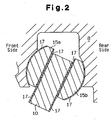
- a peripheral portion of the swash plate 10 is slidably retained at an end part of each piston 8 through a pair of front and rear shoes 15a and 15b. Accordingly, all the pistons 8 are connected to the swash plate 10. Rotational motion of the swash plate 10 following rotation of the drive shaft 9 is converted into a reciprocating motion of the piston through the shoes 15a and 15b.
- the rear housing member 4 includes a conventional control valve 16 provided to regulate a crank pressure Pc.
- the control valve 16 is provided in the midway of an air supply passage, not shown, for communicating the crank chamber 5 with the discharge chamber 7.
- the control valve 16 includes a valve mechanism for controlling the opening of the air supply passage by an electromagnetic force of a solenoid.
- the crank pressure Pc is regulated based on the balance between the amount of supplying refrigerant gas from the discharge chamber 7 through the control valve 16 to the crank chamber 5 and the amount of releasing refrigerant gas from the crank chamber 5 to the suction chamber 6 through a bleed passage, not shown, for communicating the crank chamber 5 with the suction chamber 6.
- thermoplastic polyimide coating 17 is formed at least on sliding surfaces of the swash plate 10 and the shoes 15a and 15b as sliding components of the compressor.
- the thermoplastic polyimide coating 17 is formed directly on the sliding surfaces of the swash plate 10 and the shoes 15a and 15b as component main bodies.
- the thermoplastic polyimide coating 17 may contain solid lubricant.
- solid lubricant for example, polytetrafluoroethylene (PTFE) is used.
- a relatively heavy iron-based material e.g., cast iron of FCD 700 or the like
- iron-based materials e.g., bearing steel
- thermoplastic polyimide coating 17 When the thermoplastic polyimide coating 17 is formed on the swash plate 10, first, thermoplastic polyimide powder is adhered on the sliding surface (surface slide-contacting the shoes 15a and 15b) of the swash plate 10 by electrostatic powder coating.
- thermoplastic polyimide Oram 450 (trade name) natural grade manufactured by Mitsui Chemicals, Inc. was used.
- the Oram 450 has Tg set at 250°C, and a melting point set at 388°C.
- thermoplastic polyimide powder for example, powder having an average particle size of 50 to 100 ⁇ m is used. By carrying out electrostatic powder coating at room temperature, a uniform powder coating is formed on the sliding surface. Then, the swash plate 10 is baked in an electric oven. For example, a temperature is increased from 400°C to 450°C for 30 minutes, and the swash plate 10 is held at 450°C for 15 minutes. During this period, the thermoplastic polyimide power is melted. Then, the swash plate 10 is taken out of the electric oven, and quenched by water. The quenched thermoplastic polyimide coating 17 becomes substantially amorphous, having a smooth surface. The thermoplastic polyimide coating is firmly adhered to the surface of the swash plate 10.
- Annealing is carried out for the purpose of removing residual stress.
- the annealing is executed, for example at 230°C for 2 hours.
- crystalline annealing can also be carried out.
- electrostatic powder coating is carried out by mixing the thermoplastic polyimide powder with solid lubricant powder.
- thermoplastic polyimide coating 17 In order to compare sliding performance of the thermoplastic polyimide coating 17 with that of the conventional art, sliding tests were carried out for cast-iron disks equal in size to the swash plate 10, each of which was coated with thermoplastic polyimide, or thermoplastic polyimide + PTFE, or plated with NiPB and the like. To smooth the surface, comparison was made with polished one to achieve surface roughness of Rz ⁇ 3 ⁇ m.
- thermoplastic polyimide coating according to the example 1 As shown in Table 1, it was verified that in the case of a disk with a thermoplastic polyimide coating according to the example 1, time until seizing was longer compared with the comparative examples 1 to 3 of the prior art, and high performance was exhibited as a sliding component of the compressor. In the case of a disk with a thermoplastic polyimide coating containing PTFE according to the example 2, it was confirmed that a sliding characteristic was greatly improved compared with the coating containing only thermoplastic polyimide.
- the refrigerant supplied from an unillustrated external refrigerant circuit to the suction chamber 6 is sucked through a suction port into the cylinder bore 1a, subjected to compression by a movement of the piston 8, and discharged through a discharge port to the discharge chamber 7.
- the refrigerant discharged to the discharge chamber 7 is sent out through a discharge hole to the external refrigerant circuit.
- an opening of the control valve 16 is adjusted according to a cooling load, and a communication state between the discharge chamber 7 and the crank chamber 5 is changed.
- a cooling load is high, and the pressure of the suction chamber 6 is high
- an opening of the control valve 16 becomes small, and a pressure (crank pressure Pc) of the crank chamber 5 becomes small, increasing a tilting angle of the swash plate 10.
- a stroke of the piston 8 is increased to run the compressor by a large displacement.
- a stroke of the piston 8 is reduced to run the compressor by a small displacement.
- the embodiment has the following advantages.
Landscapes
- Engineering & Computer Science (AREA)
- Mechanical Engineering (AREA)
- General Engineering & Computer Science (AREA)
- Manufacturing & Machinery (AREA)
- Compressors, Vaccum Pumps And Other Relevant Systems (AREA)
- Compressor (AREA)
- Sliding-Contact Bearings (AREA)
Claims (15)
- Procédé de formation de l'enduction sur un élément métallique ayant une surface de glissement, caractérisé par:l'adhésion d'une poudre de polyimide thermoplastique sur la surface de glissement ;la cuisson de la surface de glissement sur laquelle adhère la poudre, pour faire fondre la poudre ; etla trempe de la surface de glissement cuite pour former le revêtement de polyimide thermoplastique (17) sur la surface de glissement.
- Procédé selon la revendication 1, caractérisé par le recuit de la surface de glissement trempée.
- Procédé selon la revendication 1 ou 2, caractérisé en ce que la poudre de polyimide thermoplastique adhère à la surface de glissement grâce à l'enduction de poudre électrostatique.
- Procédé selon la revendication 1 ou 2, caractérisé en ce que la granulométrie moyenne de la poudre de polyimide thermoplastique est comprise entre 50 µm et 100 µm.
- Procédé selon la revendication 1 ou 2, caractérisé par le mélange de la poudre lubrifiante solide avec la poudre de polyimide thermoplastique, lors de l'adhésion de la poudre de polyimide thermoplastique sur la surface de glissement.
- Composant de glissement comprenant un corps métallique ayant une surface de glissement ; et caractérisé par une enduction de polyimide thermoplastique (17) formée sur la surface de glissement grâce au procédé selon l'une quelconque des revendications 1 à 5.
- Composant de glissement selon la revendication 6, caractérisé en ce que l'enduction de polyimide thermoplastique (17) contient un lubrifiant solide.
- Composant de glissement selon la revendication 7, caractérisé en ce que le lubrifiant solide est le polytétrafluoroéthylène.
- Composant de glissement selon l'une quelconque des revendications 6 à 8, caractérisé en ce que l'enduction de polyimide thermoplastique (17) est formée par l'intermédiaire de l'enduction de poudre électrostatique.
- Composant de glissement selon l'une quelconque des revendications 6 à 8, caractérisé en ce que l'enduction de polyimide thermoplastique (17) est formée par l'intermédiaire d'une pulvérisation.
- Composant de glissement selon l'une quelconque des revendications 6 à 8, caractérisé en ce que le composant de glissement est utilisé dans un compresseur.
- Composant de glissement selon la revendication 11, caractérisé en ce que le composant de glissement est un plateau oscillant (10).
- Compresseur comprenant:un arbre d'entraînement (9);un plateau oscillant (10) supporté sur l'arbre d'entraînement (9), dans lequel le plateau oscillant (10) a une première surface de glissement ;un patin (15a, 15b), dans lequel le patin (15a, 15b) a une deuxième surface de glissement coulissant sur la première surface de glissement ; etun piston (8) couplé au plateau oscillant (10) avec le patin (15a, 15b),dans lequel le plateau oscillant (10) convertit la rotation de l'arbre d'entraînement (9) en mouvement de va-et-vient du piston (8), dans lequel le patin (15a, 15b) a une troisième surface de glissement, qui coulisse sur le piston (8), dans lequel le piston (8) a une quatrième surface de glissement, qui coulisse sur la troisième surface de glissement, le compresseur étant caractérisé en ce que l'enduction de polyimide thermoplastique (17) est formée sur au moins l'une des première à quatrième surfaces de glissement, grâce à un procédé selon l'une quelconque des revendications 1 à 5.
- Compresseur selon la revendication 13, caractérisé en ce que l'enduction de polyimide thermoplastique (17) contient un lubrifiant solide.
- Compresseur selon la revendication 14, caractérisé en ce que le lubrifiant solide est le polytétrafluoroéthylène.
Applications Claiming Priority (2)
| Application Number | Priority Date | Filing Date | Title |
|---|---|---|---|
| JP2001235928 | 2001-08-03 | ||
| JP2001235928A JP2003049766A (ja) | 2001-08-03 | 2001-08-03 | 摺動部品及び圧縮機 |
Publications (3)
| Publication Number | Publication Date |
|---|---|
| EP1281863A2 EP1281863A2 (fr) | 2003-02-05 |
| EP1281863A3 EP1281863A3 (fr) | 2004-01-28 |
| EP1281863B1 true EP1281863B1 (fr) | 2007-01-17 |
Family
ID=19067289
Family Applications (1)
| Application Number | Title | Priority Date | Filing Date |
|---|---|---|---|
| EP02017303A Expired - Lifetime EP1281863B1 (fr) | 2001-08-03 | 2002-08-01 | Revêtement de compresseur |
Country Status (5)
| Country | Link |
|---|---|
| US (1) | US7021194B2 (fr) |
| EP (1) | EP1281863B1 (fr) |
| JP (1) | JP2003049766A (fr) |
| CN (1) | CN1184418C (fr) |
| DE (1) | DE60217588T2 (fr) |
Cited By (1)
| Publication number | Priority date | Publication date | Assignee | Title |
|---|---|---|---|---|
| US7811071B2 (en) | 2007-10-24 | 2010-10-12 | Emerson Climate Technologies, Inc. | Scroll compressor for carbon dioxide refrigerant |
Families Citing this family (22)
| Publication number | Priority date | Publication date | Assignee | Title |
|---|---|---|---|---|
| JP4232506B2 (ja) * | 2002-06-24 | 2009-03-04 | 株式会社豊田自動織機 | 摺動部品 |
| CN1325293C (zh) * | 2003-11-14 | 2007-07-11 | 上海三电贝洱汽车空调有限公司 | 旋转斜盘式压缩机的旋转斜盘 |
| DE602005022751D1 (de) * | 2004-10-27 | 2010-09-16 | Toyota Jidoshokki Kk | Gleitelement und herstellungsverfahren dafür |
| US7281465B2 (en) * | 2006-01-09 | 2007-10-16 | Delphi Technologies, Inc. | Compressor piston ball pocket coating |
| CN101725503A (zh) * | 2008-10-17 | 2010-06-09 | 上海三电贝洱汽车空调有限公司 | 一种压缩机滑动件 |
| CN101503995B (zh) | 2009-02-26 | 2012-06-06 | 浙江长盛滑动轴承股份有限公司 | 自润滑耐磨涂层斜盘及其生产工艺 |
| CN101806299B (zh) * | 2010-03-30 | 2012-09-05 | 浙江长盛滑动轴承股份有限公司 | 热固性聚酰亚胺耐磨自润滑斜盘及制备方法 |
| CN104945795B (zh) * | 2010-11-24 | 2019-05-21 | Agc株式会社 | 机动车用密封圈或者工业气体压缩机用密封圈或滑动构件 |
| FR2985215B1 (fr) | 2011-12-28 | 2014-09-19 | Saint Gobain Performance Plast | Revetements polymeres deposes sur des substrats par des techniques de projection thermique |
| CN103182808A (zh) | 2011-12-28 | 2013-07-03 | 圣戈班高功能塑料集团 | 一种包括含氟聚合物表面层以及非氟聚合物过渡层的多层复合物 |
| CN103998652A (zh) * | 2011-12-28 | 2014-08-20 | 美国圣戈班性能塑料公司 | 包括含氟聚合物表面与非氟化聚合物过渡层的多层复合材料 |
| CN104364079B (zh) | 2012-06-29 | 2017-12-12 | 圣戈班性能塑料帕姆普斯有限公司 | 包含底漆体系作为粘附促进剂的滑动轴承 |
| WO2014049137A1 (fr) | 2012-09-28 | 2014-04-03 | Saint-Gobain Performance Plastics Pampus Gmbh | Palier à glissement sans entretien pourvu d'une couche de glissement adhésive combinée |
| JP6230803B2 (ja) * | 2013-04-10 | 2017-11-15 | Ntn株式会社 | 斜板式コンプレッサの半球シューおよび斜板式コンプレッサ |
| JP6313681B2 (ja) * | 2014-07-23 | 2018-04-18 | Ntn株式会社 | 斜板式コンプレッサの半球シューおよび斜板式コンプレッサ |
| WO2016013558A1 (fr) * | 2014-07-23 | 2016-01-28 | Ntn株式会社 | Patin hémisphérique pour compresseur à plateau oscillant, et compresseur à plateau oscillant |
| JP6313682B2 (ja) * | 2014-07-23 | 2018-04-18 | Ntn株式会社 | 斜板式コンプレッサの半球シューおよび斜板式コンプレッサ |
| JP6313683B2 (ja) * | 2014-07-23 | 2018-04-18 | Ntn株式会社 | 斜板式コンプレッサの半球シューおよび斜板式コンプレッサ |
| US10670074B2 (en) | 2014-08-22 | 2020-06-02 | Ntn Corporation | Method for producing semispherical shoe for swash plate compressor and injection molding die |
| SE539347C2 (en) | 2015-11-02 | 2017-07-18 | Solid lubricant-coated steel articles, method and apparatus for manufacturing thereof and quenching oil used in the manufacturing | |
| CN106633865A (zh) * | 2016-10-20 | 2017-05-10 | 兰州理工大学 | 用于空气压缩机的聚酰亚胺基阀片材料及其制备方法 |
| EP4259946A4 (fr) * | 2020-12-11 | 2024-11-20 | Saint-Gobain Performance Plastics Corporation | Chemise de palier à faible frottement pour solénoïde |
Family Cites Families (12)
| Publication number | Priority date | Publication date | Assignee | Title |
|---|---|---|---|---|
| US4683804A (en) * | 1985-01-18 | 1987-08-04 | Taiho Kogyo Kabushiki Kaisha | Swash plate type compressor shoe |
| JP3234316B2 (ja) * | 1992-12-24 | 2001-12-04 | エヌティエヌ株式会社 | 摺動材用ポリイミド系樹脂組成物 |
| DE4424670B4 (de) * | 1994-07-13 | 2005-11-03 | Danfoss A/S | Hydraulische Kolbenmaschine |
| JP4023872B2 (ja) * | 1997-06-26 | 2007-12-19 | 大豊工業株式会社 | 斜板式コンプレッサー用斜板 |
| JPH11173263A (ja) | 1997-10-09 | 1999-06-29 | Toyota Autom Loom Works Ltd | 斜板式圧縮機 |
| JP3193691B2 (ja) * | 1998-09-29 | 2001-07-30 | 大同メタル工業株式会社 | 軸受構造 |
| JP4614213B2 (ja) | 1999-03-08 | 2011-01-19 | オイレス工業株式会社 | 摺動部材用樹脂組成物及びこれを使用した摺動部材 |
| JP2000257555A (ja) * | 1999-03-08 | 2000-09-19 | Toyota Autom Loom Works Ltd | 圧縮機 |
| JP4001257B2 (ja) * | 1999-03-17 | 2007-10-31 | 株式会社豊田自動織機 | 圧縮機 |
| EP1172556A3 (fr) * | 2000-07-14 | 2004-05-12 | Kabushiki Kaisha Toyota Jidoshokki | Disposition de patin glissant pour compresseur à plateau en biais |
| US6582200B2 (en) * | 2000-07-14 | 2003-06-24 | Kabushiki Kaisha Toyoda Jidoshokki Seisakusho | Swash plate compressor having shoes made of a magnesium-based material |
| JP2002039062A (ja) * | 2000-07-26 | 2002-02-06 | Toyota Industries Corp | 圧縮機 |
-
2001
- 2001-08-03 JP JP2001235928A patent/JP2003049766A/ja active Pending
-
2002
- 2002-08-01 DE DE60217588T patent/DE60217588T2/de not_active Expired - Lifetime
- 2002-08-01 EP EP02017303A patent/EP1281863B1/fr not_active Expired - Lifetime
- 2002-08-02 CN CNB021274673A patent/CN1184418C/zh not_active Expired - Fee Related
- 2002-08-02 US US10/211,008 patent/US7021194B2/en not_active Expired - Fee Related
Cited By (1)
| Publication number | Priority date | Publication date | Assignee | Title |
|---|---|---|---|---|
| US7811071B2 (en) | 2007-10-24 | 2010-10-12 | Emerson Climate Technologies, Inc. | Scroll compressor for carbon dioxide refrigerant |
Also Published As
| Publication number | Publication date |
|---|---|
| CN1401898A (zh) | 2003-03-12 |
| EP1281863A3 (fr) | 2004-01-28 |
| DE60217588T2 (de) | 2007-11-15 |
| JP2003049766A (ja) | 2003-02-21 |
| EP1281863A2 (fr) | 2003-02-05 |
| DE60217588D1 (de) | 2007-03-08 |
| US7021194B2 (en) | 2006-04-04 |
| US20030024380A1 (en) | 2003-02-06 |
| CN1184418C (zh) | 2005-01-12 |
Similar Documents
| Publication | Publication Date | Title |
|---|---|---|
| EP1281863B1 (fr) | Revêtement de compresseur | |
| US6308615B1 (en) | Compressor | |
| JP3918516B2 (ja) | 斜板式圧縮機 | |
| EP1036938B1 (fr) | Revêtement de compresseur | |
| US6123009A (en) | Swash plate of swash-plate compressor | |
| JPH11193780A (ja) | 片頭ピストン型斜板式圧縮機および斜板の製造方法 | |
| US20020104432A1 (en) | Compressor and sliding member thereof | |
| JP4232506B2 (ja) | 摺動部品 | |
| JP4285634B2 (ja) | 摺動部材 | |
| EP1548067A1 (fr) | Materiau glissant comprenant des particules plates de fluoropolymère et un liant | |
| KR100709939B1 (ko) | 슬라이딩 피막, 슬라이딩 부재, 슬라이딩 피막용 조성물,슬라이딩 장치, 사판식 압축기, 슬라이딩 피막의 형성 방법및 슬라이딩 부재의 제조 방법 | |
| EP1176310A2 (fr) | Revêtement de compresseur PEEK | |
| JP2004323594A (ja) | 塗料組成物及び摺動部品 | |
| JP2002005013A (ja) | 斜板式圧縮機 | |
| US6666128B2 (en) | Swash plate in swash plate type compressor | |
| EP1264986A1 (fr) | Plateau oscillant et compresseur l'utilisant | |
| JP2006008994A (ja) | 摺動被膜、摺動部材、摺動被膜用組成物、摺動装置、斜板式コンプレッサ、摺動被膜の形成方法および摺動部材の製造方法 | |
| US20020046646A1 (en) | Compressors | |
| JP2001050158A (ja) | 容量固定型片側斜板式圧縮機 | |
| JP2003183685A (ja) | 摺動部材 | |
| KR101147559B1 (ko) | 압축기용 사판 | |
| KR20050058608A (ko) | 압축기용 사판 및 그 표면처리방법 |
Legal Events
| Date | Code | Title | Description |
|---|---|---|---|
| PUAI | Public reference made under article 153(3) epc to a published international application that has entered the european phase |
Free format text: ORIGINAL CODE: 0009012 |
|
| 17P | Request for examination filed |
Effective date: 20020801 |
|
| AK | Designated contracting states |
Designated state(s): AT BE BG CH CY CZ DE DK EE ES FI FR GB GR IE IT LI LU MC NL PT SE SK TR |
|
| AX | Request for extension of the european patent |
Extension state: AL LT LV MK RO SI |
|
| PUAL | Search report despatched |
Free format text: ORIGINAL CODE: 0009013 |
|
| AK | Designated contracting states |
Kind code of ref document: A3 Designated state(s): AT BE BG CH CY CZ DE DK EE ES FI FR GB GR IE IT LI LU MC NL PT SE SK TR |
|
| AX | Request for extension of the european patent |
Extension state: AL LT LV MK RO SI |
|
| AKX | Designation fees paid |
Designated state(s): DE FR IT |
|
| GRAP | Despatch of communication of intention to grant a patent |
Free format text: ORIGINAL CODE: EPIDOSNIGR1 |
|
| GRAS | Grant fee paid |
Free format text: ORIGINAL CODE: EPIDOSNIGR3 |
|
| GRAA | (expected) grant |
Free format text: ORIGINAL CODE: 0009210 |
|
| AK | Designated contracting states |
Kind code of ref document: B1 Designated state(s): DE FR IT |
|
| REF | Corresponds to: |
Ref document number: 60217588 Country of ref document: DE Date of ref document: 20070308 Kind code of ref document: P |
|
| ET | Fr: translation filed | ||
| PLBE | No opposition filed within time limit |
Free format text: ORIGINAL CODE: 0009261 |
|
| STAA | Information on the status of an ep patent application or granted ep patent |
Free format text: STATUS: NO OPPOSITION FILED WITHIN TIME LIMIT |
|
| 26N | No opposition filed |
Effective date: 20071018 |
|
| PGFP | Annual fee paid to national office [announced via postgrant information from national office to epo] |
Ref country code: FR Payment date: 20090819 Year of fee payment: 8 |
|
| PGFP | Annual fee paid to national office [announced via postgrant information from national office to epo] |
Ref country code: DE Payment date: 20090828 Year of fee payment: 8 |
|
| PGFP | Annual fee paid to national office [announced via postgrant information from national office to epo] |
Ref country code: IT Payment date: 20090824 Year of fee payment: 8 |
|
| REG | Reference to a national code |
Ref country code: FR Ref legal event code: ST Effective date: 20110502 |
|
| PG25 | Lapsed in a contracting state [announced via postgrant information from national office to epo] |
Ref country code: IT Free format text: LAPSE BECAUSE OF NON-PAYMENT OF DUE FEES Effective date: 20100801 |
|
| REG | Reference to a national code |
Ref country code: DE Ref legal event code: R119 Ref document number: 60217588 Country of ref document: DE Effective date: 20110301 |
|
| PG25 | Lapsed in a contracting state [announced via postgrant information from national office to epo] |
Ref country code: FR Free format text: LAPSE BECAUSE OF NON-PAYMENT OF DUE FEES Effective date: 20100831 Ref country code: DE Free format text: LAPSE BECAUSE OF NON-PAYMENT OF DUE FEES Effective date: 20110301 |