EP1281870A2 - Pompe à tube d'entrefer - Google Patents
Pompe à tube d'entrefer Download PDFInfo
- Publication number
- EP1281870A2 EP1281870A2 EP02012052A EP02012052A EP1281870A2 EP 1281870 A2 EP1281870 A2 EP 1281870A2 EP 02012052 A EP02012052 A EP 02012052A EP 02012052 A EP02012052 A EP 02012052A EP 1281870 A2 EP1281870 A2 EP 1281870A2
- Authority
- EP
- European Patent Office
- Prior art keywords
- cover
- canned
- cover element
- motor according
- canned motor
- Prior art date
- Legal status (The legal status is an assumption and is not a legal conclusion. Google has not performed a legal analysis and makes no representation as to the accuracy of the status listed.)
- Withdrawn
Links
Images


Classifications
-
- F—MECHANICAL ENGINEERING; LIGHTING; HEATING; WEAPONS; BLASTING
- F04—POSITIVE - DISPLACEMENT MACHINES FOR LIQUIDS; PUMPS FOR LIQUIDS OR ELASTIC FLUIDS
- F04D—NON-POSITIVE-DISPLACEMENT PUMPS
- F04D13/00—Pumping installations or systems
- F04D13/02—Units comprising pumps and their driving means
- F04D13/06—Units comprising pumps and their driving means the pump being electrically driven
- F04D13/0606—Canned motor pumps
- F04D13/0633—Details of the bearings
-
- F—MECHANICAL ENGINEERING; LIGHTING; HEATING; WEAPONS; BLASTING
- F04—POSITIVE - DISPLACEMENT MACHINES FOR LIQUIDS; PUMPS FOR LIQUIDS OR ELASTIC FLUIDS
- F04D—NON-POSITIVE-DISPLACEMENT PUMPS
- F04D13/00—Pumping installations or systems
- F04D13/02—Units comprising pumps and their driving means
- F04D13/06—Units comprising pumps and their driving means the pump being electrically driven
- F04D13/0606—Canned motor pumps
- F04D13/0626—Details of the can
Definitions
- the invention relates to a canned motor for a canned pump a motor housing and with a can, which the wet room, the accommodates the rotor rotating in the conveyed liquid, from which separates the dry stator space, the wet space on the Liquid-tight opening away from the pump through a cover is closed.
- Such canned motors are generally known.
- the motor housing is often made of aluminum or other, relative cast light materials. So that the material of the motor housing is not attacked by the liquid in the can, usually a turned brass part or a turned copper part injected into the motor housing to seal the wet room.
- the object of the present invention is therefore a constructive to create simple canned motor of the type mentioned, which at low weight and permanently safe corrosion resistance can be produced particularly inexpensively.
- a canned motor Claim 1 solved. It is essential that the lid is integral with the motor housing is formed and that a cover element is provided that is at least the wet room of the canned motor covers adjacent areas of the cover in a liquid-tight manner.
- the main advantage is that the use of an expensive lathe Cover made of brass or copper is no longer required. Rather, the cover is made from one piece together with the motor housing cast, which saves both weight as well significant cost savings can be achieved. For prevention a sign of corrosion is provided, the can be manufactured and assembled relatively easily and inexpensively.
- the rotor usually rotates within the can. Doing so proposed according to the invention that the cover element the lid seals against the interior of the can.
- the rotor can also circulate outside the can, so that the drying room with the Stator inside the can and the wet room with the rotor outside of the can are formed.
- the cover element make the lid annular opposite the space between the motor housing and the Seals the outer wall of the can.
- a particularly good seal can be achieved in that the Cover element via a sealant, in particular via an O-ring, is sealed off from the wet room.
- the motor housing can be produced in a particularly simple manner in terms of production technology be cast in one piece with the lid.
- the motor housing with the cover from a Aluminum alloy or from a zinc alloy or from plastic is cast, whereby particularly low engine weights are achieved can be.
- the cover element from a to produce corrosion-resistant material.
- that can Cover element made of a brass and / or copper alloy his.
- the cover element can advantageously also be made of a chromium-nickel alloy be made.
- a particularly inexpensive method of production can be achieved be that the cover is made by deep drawing. At the same time, using a simple thermoformed part low wall thickness a particularly low weight can be achieved.
- the cover element is cup-shaped and in a central recess inserted, which the cover has inside the motor.
- the pot-shaped training can preferably be produced by deep drawing.
- the cover element at least one projecting radially outwards and / or axially in the direction of the cover Has projection, the form-fitting in a corresponding recess of the lid.
- the projection of the cover element can be particularly simple a bead can be formed in the cover element.
- the recess in the lid can be special in terms of production technology conveniently poured into the lid.
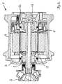
- the canned motor 1 shown in FIGS. 1 to 3 is used for driving a centrifugal pump, not shown, with one on the motor shaft 2 mounted pump impeller 3.
- the motor housing 4 there is a can 5 arranged, the wet room formed in the interior of the can 5 6 separates from the drying space 7 formed outside the can.
- the rotor 8 runs as a wet rotor in the pump pumped liquid around.
- the associated stator 9 is located radially on the outside with elements 10 of the motor electronics in the drying room 7 arranged.
- the can 5 is at the end facing away from the pump impeller 3 closed by a lid 11.
- the cover 11 is in one piece with the motor housing 4 cast from aluminum. At the wet room 6 facing side, the cover 11 has a central recess 12 in which a bearing 13 is received for mounting the motor shaft 2.
- a cover element 14 which connects the wet room 6 adjacent areas of the cover 11 covers liquid-tight.
- the Cover element 14 consists of a chrome-nickel alloy and is formed by deep drawing so that a pot-shaped area in the middle 15 is formed, which lies in the recess 12 of the lid 11 and in which the bearing 13 is added.
- the top edge 16 of the cover member 14 is in shape on the inside contour of the lid adapted and shows a radial in the example shown externally directed collar 16, which in its central region is a Gradation 17 pointing in the direction of the pot-shaped region 15. in the The area of this gradation 17 is an O-ring 18 between the inner wall of the can 5 and the cover member 14 used to make a liquid-tight Ensure closure of the wet room 6.
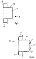
- the inside Unscrew the recess 12 of the lid 11 and after subsequent insertion of the cover element 14 also an inside Turning of the pot-shaped area 15 of the cover element 14 to be required. So that here the cover element 14 is not due the cutting forces can twist in the lid 11 are in the embodiment 2 and 5 in the bottom 19 of the cup-shaped Area 15 of the cover element 14 formed two axial projections 20, each in a corresponding recess 21 in the bottom of the Insert recess 12 of cover 11 in a form-fitting manner. This form fit prevents relative rotation between the lid 11 and the Cover element 14. In a particularly simple and inexpensive way the recesses 21 can be poured directly into the cover 11 and the projections 20 by beads during the deep drawing of the cover element 14 are introduced.
- the motor housing 4 cast cast brass part 22 is in the Training of the canned motor 1 according to the invention no longer required.
- the cover 14 can be particularly constructive simple and therefore very cost-effective way of corrosion of the prevented in one piece with the motor housing 4 formed cover 11 become.
Landscapes
- Engineering & Computer Science (AREA)
- Mechanical Engineering (AREA)
- General Engineering & Computer Science (AREA)
- Motor Or Generator Frames (AREA)
- Structures Of Non-Positive Displacement Pumps (AREA)
Applications Claiming Priority (2)
| Application Number | Priority Date | Filing Date | Title |
|---|---|---|---|
| DE10137885 | 2001-08-02 | ||
| DE2001137885 DE10137885A1 (de) | 2001-08-02 | 2001-08-02 | Spaltrohrmotor mit Abdeckelementen |
Publications (2)
| Publication Number | Publication Date |
|---|---|
| EP1281870A2 true EP1281870A2 (fr) | 2003-02-05 |
| EP1281870A3 EP1281870A3 (fr) | 2004-01-07 |
Family
ID=7694121
Family Applications (1)
| Application Number | Title | Priority Date | Filing Date |
|---|---|---|---|
| EP02012052A Withdrawn EP1281870A3 (fr) | 2001-08-02 | 2002-05-29 | Pompe à tube d'entrefer |
Country Status (2)
| Country | Link |
|---|---|
| EP (1) | EP1281870A3 (fr) |
| DE (1) | DE10137885A1 (fr) |
Cited By (2)
| Publication number | Priority date | Publication date | Assignee | Title |
|---|---|---|---|---|
| DE102007043600A1 (de) | 2007-09-13 | 2009-03-19 | Robert Bosch Gmbh | Pumpenrotor für eine Spaltrohrpumpe |
| WO2015197161A1 (fr) * | 2014-06-23 | 2015-12-30 | Wilo Se | Motopompe à rotor noyé |
Families Citing this family (2)
| Publication number | Priority date | Publication date | Assignee | Title |
|---|---|---|---|---|
| DE102009049904A1 (de) * | 2009-10-12 | 2011-04-14 | Deutsche Vortex Gmbh & Co. Kg | Trennwand für einen Elektromotor und Pumpe mit Elektromotor |
| DE102020121421A1 (de) | 2020-08-14 | 2022-02-17 | Dr. Ing. H.C. F. Porsche Aktiengesellschaft | Elektrische Maschine |
Family Cites Families (8)
| Publication number | Priority date | Publication date | Assignee | Title |
|---|---|---|---|---|
| BE644859A (fr) * | 1963-03-06 | |||
| US3967915A (en) * | 1975-01-27 | 1976-07-06 | Litzenberg David P | Centrifugal pump |
| DE3818832A1 (de) * | 1988-06-03 | 1989-12-07 | Uranit Gmbh | Spalttopf fuer stopfbuchsenlose elektrische oder magnetische antriebsaggregate |
| DE4023756C1 (fr) * | 1990-07-26 | 1991-12-19 | Grundfos International A/S, Bjerringbro, Dk | |
| FR2668556B1 (fr) * | 1990-10-29 | 1995-01-27 | Salmson Pompes | Corps de chambre sous pression et groupe motopompe utilisant un tel corps. |
| DE4129590C3 (de) * | 1991-09-06 | 2002-03-07 | Progress Werk Oberkirch Ag | Verfahren zum Herstellen eines Spalttopfes für einen Spaltrohrmotor sowie Spalttopf für einen derartigen Spaltrohrmotor |
| DE4208829C2 (de) * | 1992-03-19 | 1995-04-27 | Wilo Gmbh | Spaltrohrmotorpumpe |
| DE19939522A1 (de) * | 1999-08-20 | 2001-02-22 | Wilo Gmbh | Elektromotorisch angetriebene Kreiselpumpe mit außenliegendem Rotor |
-
2001
- 2001-08-02 DE DE2001137885 patent/DE10137885A1/de not_active Withdrawn
-
2002
- 2002-05-29 EP EP02012052A patent/EP1281870A3/fr not_active Withdrawn
Cited By (3)
| Publication number | Priority date | Publication date | Assignee | Title |
|---|---|---|---|---|
| DE102007043600A1 (de) | 2007-09-13 | 2009-03-19 | Robert Bosch Gmbh | Pumpenrotor für eine Spaltrohrpumpe |
| WO2009037019A1 (fr) | 2007-09-13 | 2009-03-26 | Robert Bosch Gmbh | Rotor de pompe pour pompe à moteur à gaine |
| WO2015197161A1 (fr) * | 2014-06-23 | 2015-12-30 | Wilo Se | Motopompe à rotor noyé |
Also Published As
| Publication number | Publication date |
|---|---|
| DE10137885A1 (de) | 2003-02-20 |
| EP1281870A3 (fr) | 2004-01-07 |
Similar Documents
| Publication | Publication Date | Title |
|---|---|---|
| EP1725775B1 (fr) | Ensemble comprenant un moteur a induit exterieur a commutation electronique | |
| DE4331560B4 (de) | Magnetisch gekuppelte Kreiselpumpe | |
| DE69515564T2 (de) | Seitenkanal-Pumpe mit geräuschdämpfender Vorrichtung | |
| EP1309070A2 (fr) | Motopompe à rotor noyé avec dispositif de protection contre la corrosion | |
| DE60218006T2 (de) | Eingetauchte, elektrische Fluidpumpe | |
| DE202008002617U1 (de) | Anordnung zur Förderung von Fluiden | |
| DE102013014143A1 (de) | Elektromotorische Wasserpumpe | |
| EP0945624B1 (fr) | Pompe pour liquide de refroidissement | |
| DE19907561B4 (de) | Elektrisch betriebene Pumpenvorrichtung mit verbesserter Luftkanalkonstuktion | |
| DE102016002832A1 (de) | Lüfter | |
| DE10140613A1 (de) | Naßläuferpumpe | |
| EP1940664B1 (fr) | Unite hydraulique pour un systeme hydraulique de freinage de vehicule a regulation du patinage | |
| EP3158200B1 (fr) | Motopompe à rotor noyé | |
| DE3818027A1 (de) | Wasserpumpeneinheit fuer kraftmaschinen und verfahren zu deren herstellung | |
| EP0536441B1 (fr) | Boîtier de moteur pourvu d'un trou d'écoulement dans sa partie basse | |
| DE3637501C2 (de) | Axialschubkompensation für Zentrifugalpumpen | |
| EP1281870A2 (fr) | Pompe à tube d'entrefer | |
| EP1768233A1 (fr) | Tube d'entrefer | |
| EP2228538B1 (fr) | Agrégat de pompe centrifuge à plusieurs niveaux | |
| DE10012663B4 (de) | Kühlmittelpumpe mit elektronisch kommutiertem Eletromotor | |
| DE69414344T2 (de) | Seitenströmungspumpe | |
| DE10221843A1 (de) | Elektromotor zur Verwendung als Pumpenmotor und Pumpe | |
| DE102006013536B4 (de) | Fluiddynamisches Lagersystem | |
| DE4310466A1 (de) | Pumpenstufe in Blechbauweise | |
| DE2623583A1 (de) | Kreiselpumpe, insbesondere kuehlwasserpumpe fuer kraftfahrzeuge |
Legal Events
| Date | Code | Title | Description |
|---|---|---|---|
| PUAI | Public reference made under article 153(3) epc to a published international application that has entered the european phase |
Free format text: ORIGINAL CODE: 0009012 |
|
| AK | Designated contracting states |
Designated state(s): AT BE CH CY DE DK ES FI FR GB GR IE IT LI LU MC NL PT SE TR |
|
| AX | Request for extension of the european patent |
Extension state: AL LT LV MK RO SI |
|
| PUAL | Search report despatched |
Free format text: ORIGINAL CODE: 0009013 |
|
| AK | Designated contracting states |
Kind code of ref document: A3 Designated state(s): AT BE CH CY DE DK ES FI FR GB GR IE IT LI LU MC NL PT SE TR |
|
| AX | Request for extension of the european patent |
Extension state: AL LT LV MK RO SI |
|
| 17P | Request for examination filed |
Effective date: 20040420 |
|
| AKX | Designation fees paid |
Designated state(s): DE FR GB IT |
|
| 17Q | First examination report despatched |
Effective date: 20061229 |
|
| STAA | Information on the status of an ep patent application or granted ep patent |
Free format text: STATUS: THE APPLICATION IS DEEMED TO BE WITHDRAWN |
|
| 18D | Application deemed to be withdrawn |
Effective date: 20151201 |