EP1281896A2 - Thermoplastischer Hohlkörper sowie Verfahren und Vorrichtung zu dessen Herstellung - Google Patents
Thermoplastischer Hohlkörper sowie Verfahren und Vorrichtung zu dessen Herstellung Download PDFInfo
- Publication number
- EP1281896A2 EP1281896A2 EP02253835A EP02253835A EP1281896A2 EP 1281896 A2 EP1281896 A2 EP 1281896A2 EP 02253835 A EP02253835 A EP 02253835A EP 02253835 A EP02253835 A EP 02253835A EP 1281896 A2 EP1281896 A2 EP 1281896A2
- Authority
- EP
- European Patent Office
- Prior art keywords
- nozzle
- hollow article
- thermoplastic resin
- blow
- parison
- Prior art date
- Legal status (The legal status is an assumption and is not a legal conclusion. Google has not performed a legal analysis and makes no representation as to the accuracy of the status listed.)
- Withdrawn
Links
- 229920005992 thermoplastic resin Polymers 0.000 title claims abstract description 49
- 238000000034 method Methods 0.000 title claims description 9
- 238000004519 manufacturing process Methods 0.000 claims abstract description 41
- 238000000071 blow moulding Methods 0.000 claims description 39
- 238000001746 injection moulding Methods 0.000 claims description 15
- 230000003750 conditioning effect Effects 0.000 claims description 6
- 238000002347 injection Methods 0.000 claims description 5
- 239000007924 injection Substances 0.000 claims description 5
- 229920005989 resin Polymers 0.000 claims description 5
- 239000011347 resin Substances 0.000 claims description 5
- 238000000465 moulding Methods 0.000 claims description 4
- 239000004033 plastic Substances 0.000 abstract description 7
- 238000007664 blowing Methods 0.000 abstract description 5
- 238000010276 construction Methods 0.000 description 12
- 239000000047 product Substances 0.000 description 8
- 239000007788 liquid Substances 0.000 description 6
- 239000002699 waste material Substances 0.000 description 4
- 230000005540 biological transmission Effects 0.000 description 2
- 238000010586 diagram Methods 0.000 description 2
- 239000012467 final product Substances 0.000 description 2
- 230000005291 magnetic effect Effects 0.000 description 2
- 239000000463 material Substances 0.000 description 2
- 238000005259 measurement Methods 0.000 description 2
- 239000011358 absorbing material Substances 0.000 description 1
- 238000010101 extrusion blow moulding Methods 0.000 description 1
- 239000003302 ferromagnetic material Substances 0.000 description 1
- 238000010102 injection blow moulding Methods 0.000 description 1
- 230000002093 peripheral effect Effects 0.000 description 1
- 230000000630 rising effect Effects 0.000 description 1
- 229920002725 thermoplastic elastomer Polymers 0.000 description 1
- 238000003079 width control Methods 0.000 description 1
Images




Classifications
-
- B—PERFORMING OPERATIONS; TRANSPORTING
- B29—WORKING OF PLASTICS; WORKING OF SUBSTANCES IN A PLASTIC STATE IN GENERAL
- B29C—SHAPING OR JOINING OF PLASTICS; SHAPING OF MATERIAL IN A PLASTIC STATE, NOT OTHERWISE PROVIDED FOR; AFTER-TREATMENT OF THE SHAPED PRODUCTS, e.g. REPAIRING
- B29C49/00—Blow-moulding, i.e. blowing a preform or parison to a desired shape within a mould; Apparatus therefor
- B29C49/28—Blow-moulding apparatus
-
- B—PERFORMING OPERATIONS; TRANSPORTING
- B29—WORKING OF PLASTICS; WORKING OF SUBSTANCES IN A PLASTIC STATE IN GENERAL
- B29C—SHAPING OR JOINING OF PLASTICS; SHAPING OF MATERIAL IN A PLASTIC STATE, NOT OTHERWISE PROVIDED FOR; AFTER-TREATMENT OF THE SHAPED PRODUCTS, e.g. REPAIRING
- B29C49/00—Blow-moulding, i.e. blowing a preform or parison to a desired shape within a mould; Apparatus therefor
- B29C49/02—Combined blow-moulding and manufacture of the preform or the parison
-
- B—PERFORMING OPERATIONS; TRANSPORTING
- B29—WORKING OF PLASTICS; WORKING OF SUBSTANCES IN A PLASTIC STATE IN GENERAL
- B29C—SHAPING OR JOINING OF PLASTICS; SHAPING OF MATERIAL IN A PLASTIC STATE, NOT OTHERWISE PROVIDED FOR; AFTER-TREATMENT OF THE SHAPED PRODUCTS, e.g. REPAIRING
- B29C49/00—Blow-moulding, i.e. blowing a preform or parison to a desired shape within a mould; Apparatus therefor
- B29C49/02—Combined blow-moulding and manufacture of the preform or the parison
- B29C49/04—Extrusion blow-moulding
- B29C49/0411—Means for defining the wall or layer thickness
- B29C49/04112—Means for defining the wall or layer thickness for varying the thickness
-
- F—MECHANICAL ENGINEERING; LIGHTING; HEATING; WEAPONS; BLASTING
- F16—ENGINEERING ELEMENTS AND UNITS; GENERAL MEASURES FOR PRODUCING AND MAINTAINING EFFECTIVE FUNCTIONING OF MACHINES OR INSTALLATIONS; THERMAL INSULATION IN GENERAL
- F16D—COUPLINGS FOR TRANSMITTING ROTATION; CLUTCHES; BRAKES
- F16D3/00—Yielding couplings, i.e. with means permitting movement between the connected parts during the drive
- F16D3/84—Shrouds, e.g. casings, covers; Sealing means specially adapted therefor
- F16D3/843—Shrouds, e.g. casings, covers; Sealing means specially adapted therefor enclosed covers
- F16D3/845—Shrouds, e.g. casings, covers; Sealing means specially adapted therefor enclosed covers allowing relative movement of joint parts due to the flexing of the cover
-
- B—PERFORMING OPERATIONS; TRANSPORTING
- B29—WORKING OF PLASTICS; WORKING OF SUBSTANCES IN A PLASTIC STATE IN GENERAL
- B29C—SHAPING OR JOINING OF PLASTICS; SHAPING OF MATERIAL IN A PLASTIC STATE, NOT OTHERWISE PROVIDED FOR; AFTER-TREATMENT OF THE SHAPED PRODUCTS, e.g. REPAIRING
- B29C49/00—Blow-moulding, i.e. blowing a preform or parison to a desired shape within a mould; Apparatus therefor
- B29C49/42—Component parts, details or accessories; Auxiliary operations
- B29C49/48—Moulds
- B29C49/54—Moulds for undercut articles
- B29C2049/542—Moulds for undercut articles having means to facilitate the removal of the blow moulded articles
- B29C2049/543—Moulds for undercut articles having means to facilitate the removal of the blow moulded articles at the neck portion
-
- B—PERFORMING OPERATIONS; TRANSPORTING
- B29—WORKING OF PLASTICS; WORKING OF SUBSTANCES IN A PLASTIC STATE IN GENERAL
- B29C—SHAPING OR JOINING OF PLASTICS; SHAPING OF MATERIAL IN A PLASTIC STATE, NOT OTHERWISE PROVIDED FOR; AFTER-TREATMENT OF THE SHAPED PRODUCTS, e.g. REPAIRING
- B29C49/00—Blow-moulding, i.e. blowing a preform or parison to a desired shape within a mould; Apparatus therefor
- B29C49/42—Component parts, details or accessories; Auxiliary operations
- B29C49/48—Moulds
- B29C49/54—Moulds for undercut articles
-
- B—PERFORMING OPERATIONS; TRANSPORTING
- B29—WORKING OF PLASTICS; WORKING OF SUBSTANCES IN A PLASTIC STATE IN GENERAL
- B29K—INDEXING SCHEME ASSOCIATED WITH SUBCLASSES B29B, B29C OR B29D, RELATING TO MOULDING MATERIALS OR TO MATERIALS FOR MOULDS, REINFORCEMENTS, FILLERS OR PREFORMED PARTS, e.g. INSERTS
- B29K2101/00—Use of unspecified macromolecular compounds as moulding material
- B29K2101/12—Thermoplastic materials
-
- B—PERFORMING OPERATIONS; TRANSPORTING
- B29—WORKING OF PLASTICS; WORKING OF SUBSTANCES IN A PLASTIC STATE IN GENERAL
- B29L—INDEXING SCHEME ASSOCIATED WITH SUBCLASS B29C, RELATING TO PARTICULAR ARTICLES
- B29L2031/00—Other particular articles
- B29L2031/703—Bellows
-
- F—MECHANICAL ENGINEERING; LIGHTING; HEATING; WEAPONS; BLASTING
- F16—ENGINEERING ELEMENTS AND UNITS; GENERAL MEASURES FOR PRODUCING AND MAINTAINING EFFECTIVE FUNCTIONING OF MACHINES OR INSTALLATIONS; THERMAL INSULATION IN GENERAL
- F16D—COUPLINGS FOR TRANSMITTING ROTATION; CLUTCHES; BRAKES
- F16D3/00—Yielding couplings, i.e. with means permitting movement between the connected parts during the drive
- F16D3/16—Universal joints in which flexibility is produced by means of pivots or sliding or rolling connecting parts
- F16D3/20—Universal joints in which flexibility is produced by means of pivots or sliding or rolling connecting parts one coupling part entering a sleeve of the other coupling part and connected thereto by sliding or rolling members
- F16D3/202—Universal joints in which flexibility is produced by means of pivots or sliding or rolling connecting parts one coupling part entering a sleeve of the other coupling part and connected thereto by sliding or rolling members one coupling part having radially projecting pins, e.g. tripod joints
- F16D3/205—Universal joints in which flexibility is produced by means of pivots or sliding or rolling connecting parts one coupling part entering a sleeve of the other coupling part and connected thereto by sliding or rolling members one coupling part having radially projecting pins, e.g. tripod joints the pins extending radially outwardly from the coupling part
- F16D3/2055—Universal joints in which flexibility is produced by means of pivots or sliding or rolling connecting parts one coupling part entering a sleeve of the other coupling part and connected thereto by sliding or rolling members one coupling part having radially projecting pins, e.g. tripod joints the pins extending radially outwardly from the coupling part having three pins, i.e. true tripod joints
-
- Y—GENERAL TAGGING OF NEW TECHNOLOGICAL DEVELOPMENTS; GENERAL TAGGING OF CROSS-SECTIONAL TECHNOLOGIES SPANNING OVER SEVERAL SECTIONS OF THE IPC; TECHNICAL SUBJECTS COVERED BY FORMER USPC CROSS-REFERENCE ART COLLECTIONS [XRACs] AND DIGESTS
- Y10—TECHNICAL SUBJECTS COVERED BY FORMER USPC
- Y10T—TECHNICAL SUBJECTS COVERED BY FORMER US CLASSIFICATION
- Y10T428/00—Stock material or miscellaneous articles
- Y10T428/13—Hollow or container type article [e.g., tube, vase, etc.]
- Y10T428/1352—Polymer or resin containing [i.e., natural or synthetic]
- Y10T428/139—Open-ended, self-supporting conduit, cylinder, or tube-type article
Definitions
- the present invention relates to a hollow article made of a thermoplastic resin and having both end portions whose wall thickness changes multidirectionally with extremely high accuracy, such as tri-port type CV-joint boots for automobiles.
- a hollow article 8 such as a CV-joint boot for an automobile is known.
- one end portion (the upper end portion in FIG. 7) 40 has been formed by injection molding and all other portions have been formed by blow molding.
- an apparatus illustrated in FIG. 6 Japanese Patent No. 2556647.
- the apparatus illustrated in FIG. 6 is a parison manufacturing apparatus for blow-molding bellows (hollow article) 8, in which the bellows is blow-molded with its cross-sectional profile being changed into a wave shape through the whole length of a parison 18, as illustrated in FIG. 6. Since the circular parison 18 is never flatly compressed, the plastic is extended evenly throughout the whole periphery. This prior art is very superior for molding such bellows 8. In the bellows molded with this apparatus, since its one end portion (the upper end portion in FIG. 6) 40 is injection-molded with a neck mold, the thickness of that portion can be changed multidirectionally on the circumference with high accuracy.
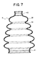
- the apparatus can provide only such a general automobile CV-joint boot (bellows) 8 as illustrated in FIG. 7.
- a general automobile CV-joint boot (bellows) 8 as illustrated in FIG. 7.
- some tri-port type CV-joint boots may require not only a high dimensional accuracy at the one end portion 40 (the wall thickness must be changed multidirectionally with high accuracy) but also a high dimensional accuracy at the other end portion (the lower end portion in FIG.
- 10-272679 discloses a method in which, upon injection-blow molding, the mold for the final product shape portion (portion corresponding to the other end portion 41 in the above-described prior art) is not changed for injection molding and for blow molding and it is successively molded, and thereby no flash is generated and the dimensional accuracy is kept.
- Japanese Patent No. 2556647 Japanese Patent No. 2556647
- Japanese Patent No. 2556647 Japanese Patent No. 2556647
- the present applicant has succeeded in newly developing a hollow article made of a thermoplastic resin and having both end portions whose wall thickness changes multidirectionally with extremely high accuracy, a manufacturing method of the hollow article, and a manufacturing apparatus for the hollow article.
- the present invention has been developed in view of such problems of the prior art, and its object is to provide a hollow article made of a thermoplastic resin and having both end portions whose wall thickness changes multidirectionally with extremely high accuracy.
- a hollow article made of a thermoplastic resin is formed by bringing a cavity of a drawing unit into contact with an outlet gap of an annular orifice nozzle made up of a nozzle core constituted so as to be upwardly and downwardly movable, and a nozzle mouthpiece concentrically surrounding said core to form said outlet gap having a variable gap width for upward extruding the thermoplastic resin between it and said core; injecting the thermoplastic resin into said cavity through said outlet gap to form one end portion having a configuration in which a wall thickness changes multidirectionally with extremely high accuracy; drawing and forming a tubular parison while moving said drawing unit apart from said annular orifice; blow-molding the tubular parison after replacing an uppermost portion of said nozzle mouthpiece constituting said outlet gap with a blow mold to form a hollow article body; injection-molding the other end portion of a hollow article having a configuration in which a wall thickness changes multidirectionally with extremely high accuracy, through
- a manufacturing apparatus for the hollow article is as follows.
- the apparatus comprises an annular orifice nozzle made up of a nozzle core constituted so as to be upwardly and downwardly movable, and a nozzle mouthpiece concentrically surrounding said core to form an outlet gap having a variable gap width for upward extruding a thermoplastic resin between it and said core; a drawing unit having a cavity of a desired shape downward opened for forming one end portion of a hollow article, said drawing unit being moved apart from said annular orifice nozzle to draw and form a tubular parison after injecting the thermoplastic resin into said cavity on said outlet gap of said annular orifice nozzle; and a blow mold for blow-molding said tubular parison to form a hollow article body of a desired shape, wherein said nozzle mouthpiece is multi-divided vertically and laterally, each divided part is disposed so as to be able to reciprocate laterally, an uppermost portion of said nozzle mouthpiece divided is constituted so as to be replaceable with said blow mold upon blow molding, and a lower portion of said
- the nozzle mouthpiece multi-divided vertically and laterally can have an individual independent temperature conditioning system to set the thermoplastic resin in the nozzle mouthpiece at a proper temperature any time.
- a manufacturing method of the above hollow article comprises the steps of bringing a cavity of a drawing unit into contact with an outlet gap of an annular orifice nozzle made up of a nozzle core constituted so as to be upwardly and downwardly movable, and a nozzle mouthpiece concentrically surrounding said core to form said outlet gap having a variable gap width for upward extruding a thermoplastic resin between it and said core; injecting the thermoplastic resin into said cavity through said outlet gap to form one end portion having a configuration in which a wall thickness changes multidirectionally with extremely high accuracy; drawing and forming a tubular parison while moving said drawing unit apart from said annular orifice; blow-molding the tubular parison after replacing an uppermost portion of said nozzle mouthpiece constituting said outlet gap with a blow mold to form a hollow article body; injection-molding the other end portion of a hollow article having a configuration in which a wall thickness changes multidirectionally with extremely high accuracy, with a cavity having a desired shape at a lower portion of said
- the shape of the one end portion is determined by the cavity shape of the neck mold.
- the shape of the other end portion is determined by that the cavity (space shape) defined by the nozzle mouthpiece of the annular orifice nozzle and the outer side surface of the nozzle core serves as a flow passage for the thermoplastic resin when pushing into the neck mold and when extruding the parison, and keeps the thermoplastic resin filling up the lower portion of the space shape upon blow molding.
- thermoplastic resin filling up the upper portion of the annular orifice nozzle is expanded to the inner wall surface of the blow mold by compressed gas blown into the parison after part of the upper portion of the nozzle mouthpiece is replaced with the blow mold while keeping the nozzle core intact, and the shapes of the parison and the other end become one continuous body.
- the nozzle mouthpiece multi-divided vertically and laterally can have an individual independent temperature conditioning system, and it can be adjusted and set at temperatures at which the thermoplastic resin in the nozzle mouthpiece is made easy to flow upon flowing, easy to blow upon blowing, and solidified at a short time.
- the present invention provides not only the manufacturing apparatus of the hollow article but also a method for molding a specific hollow article by manufacturing a specific parison and a specific shape using a specific apparatus.
- the present invention can also make it: possible to, for example, first push a thermoplastic resin into a cavity of a neck mold in contact with an annular orifice nozzle for plastic, then form a parison with moving said neck mold apart from said annular orifice nozzle, said parison being a tubular parison having various different cross-sections throughout the whole length of the parison so that the wall thickness of the parison formed may change into a wave shape through troughs and peaks, operate a controller for a drive unit for moving the neck mold onto/apart and a controller for a drive unit for changing plastic flowing out through an outlet gap of said annular orifice nozzle, while moving the neck mold apart from said annular orifice nozzle, said outlet gap of said annular orifice nozzle being changed in accordance with the quantity of the plastic
- the characteristic features of the present invention are in that the nozzle mouthpiece constituting the annular orifice nozzle is multi-divided vertically and laterally, each divided portion is disposed so as to be able to reciprocate laterally, part of the upper portion of the nozzle mouthpiece is replaced with the blow mold, and further, part lower than that keeps the thermoplastic resin filling up also upon blowing and is made to be able to open and close for taking out a product, and thereby, a hollow article is formed having both end portions whose wall thickness changes multidirectionally with extremely high accuracy.
- a hollow article of the present invention can be constructed in consideration of various use objects. Besides, the manufacturing method and the manufacturing apparatus for the hollow article of the present invention are particularly advantageous because they are constructed so that they can manufacture tri-port type CV-joint boots. Such a boot is provided for use on the transmission side of an automobile, and it requires not only a high accuracy in dimension of one end portion but also, in the other end portion, an accurate configuration in which the wall thickness changes multidirectionally, i.e., the profile of the outer periphery must be made into an accurate circle while protrusions are formed on the inner peripheral side.
- the bellows manufactured according to the present invention is made of a thermoplastic elastomer, but also in that high accurate bellows both end portions can be obtained because it can be manufactured with more accuracy by setting the neck mold, the annular orifice nozzle, and the divided nozzle mouthpiece.
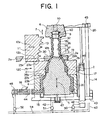
- FIG. 1 is a vertical sectional view illustrating an embodiment of a manufacturing apparatus for a hollow article made of a thermoplastic resin according to the present invention
- FIG. 2 is a block diagram illustrating the construction of a controller of the manufacturing apparatus for the hollow article
- FIG. 3 is a conceptional view of a stroke measuring device
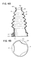
- FIG. 4 illustrates an embodiment of the hollow article made of the thermoplastic resin, in which (a) is a vertical sectional view and (b) is a bottom view
- FIG. 5 is a schematic view illustrating steps of a manufacturing method for the hollow article according to the present invention.
- a hollow article of the present invention comprises both end portions 40 and 41 each having a constitution in which the wall thickness of these end portions formed by injection molding a thermoplastic resin changes multidirectionally with extremely high accuracy, and a hollow article body (bellows) 8 integrally formed by blow molding between both end portions 40 and 41.
- a typical example thereof is a tri-port type CV-joint boot for an automobile illustrated in, e.g., FIG. 4 by way of example.
- Both end portions of the blow-molded bellows as the hollow article body 8, i.e., one end portion 40 as the upper end portion in FIG. 1 and the other end portion 41 as the lower end portion, are each constructed so as to have a configuration in which the wall thickness changes multidirectionally with extremely high accuracy (see FIG.
- the one end portion 40 is formed so that the inner diameter 40a is made into a substantially accurate circle and the outer diameter 40b is made uneven in height on the periphery.
- the other end portion 41 is formed so that the outer diameter 41a is made into a substantially accurate circle and the inner diameter 41b is made uneven in height on the periphery.
- Either of both end portions 40 and 41 thus has a configuration in which the wall thickness changes multidirectionally.
- this uneven shape is not particularly limited, since both end portions 40 and 41 are formed by injection molding, a multidirectional change in wall thickness can be obtained with extremely high accuracy.
- the shape of this hollow article body 8 should not be interpreted limitedly to the illustrated shape.
- both end portions 40 and 41 i.e., the configuration in which the wall thickness changes multidirectionally
- the thermoplastic resin as the material of the hollow article should not particularly be limitedly interpreted, and the optimum material can properly be selected within the scope of the present invention.
- a tri-port type CV-joint boot for an automobile is described as an embodiment of the hollow article, this only shows one optimum embodiment.
- the hollow article of the present invention should not at all be interpreted limitedly to this, and any other form can properly be selected within the scope of the present invention.
- a manufacturing apparatus for a tri-port type CV-joint boot (hollow article) for an automobile illustrated in, e.g., FIG. 1 is mentioned as a typical example.
- the hollow article manufacturing apparatus illustrated in FIG. 1 it is made up of an annular orifice nozzle 30, a drawing unit 6, and a blow mold 11.
- the manufacturing apparatus of the present invention is constructed so that a nozzle mouthpiece of the annular orifice nozzle 30 is multi-divided and the divided nozzle mouthpiece can reciprocate laterally, and part of the nozzle mouthpiece is replaceable with the blow mold 11. It has a characteristic feature in a relation between such a construction and the drawing unit 6.
- the annular orifice nozzle 30 is made up of a nozzle core 1 constituted so as to upwardly and downwardly move, and nozzle mouthpieces 2a, 2b, and 2c concentrically surrounding the nozzle core 1.
- the nozzle core 1 and the nozzle mouthpiece 2a define an outlet gap 3 in the form of an annular orifice at the upper portion.
- a thermoplastic resin 4 is supplied to the outlet gap 3 through an annular chamber between the nozzle core 1 and the nozzle mouthpiece 2a.
- the nozzle mouthpiece is made up of three parts, i.e., the nozzle mouthpieces 2a, 2b, and 2c (three-divided construction).
- the nozzle mouthpieces 2a and 2b are vertically fixed and each laterally two-divided so as to be able to open and close. Note that, in this embodiment, although the nozzle mouthpiece is vertically three-divided and laterally two-divided, this is nothing but only one embodiment, and the vertical and lateral division construction is optional.
- the nozzle mouthpiece 2b has a cavity 17 on the inner circumference for injection-molding the other end portion (the lower end portion in FIG. 1) of the hollow article with the outer circumference of the nozzle core 1.
- the nozzle core 1 has a size/shape so as to form a desired flow passage between it and the nozzle mouthpieces 2a, 2b, and 2c.
- the nozzle mouthpiece 2b On the outer circumferential surface opposite to the cavity 17 of the nozzle mouthpiece 2b, it has a shape corresponding to the inner diameter 41a of the other end portion 41 of the hollow article to be injection-molded, and it is constructed so as to be upwardly and downwardly movable in an axial direction (vertically in FIG. 1) in accordance with an arrow 5 in FIG. 1.
- the construction of the flow passage is not particularly limited and it can be changed in design within the scope of the present invention at need.
- the other end portion 41 of the hollow article is injection-molded so as to have a configuration in which the wall thickness changes so that the outer diameter 41b is made into an accurate circle and the inner diameter 41a is uneven in height
- the inner surface shape of the cavity 17 is made into a shape corresponding to that and the outer circumferential shape of the nozzle core 1 is made into a shape corresponding to the uneven shape of the inner diameter 41a.
- any one or either of the inner and outer diameters 41a and 41b of the other end portion 41 of the hollow article has a shape which can be injection-molded so as to have a construction in which the wall thickness changes multidirectionally
- the inner surface shape of the cavity 17 and the outer circumferential shape of the nozzle core 1 should not particularly be limitedly interpreted and they can properly be changed in design within the scope of the present invention.
- the nozzle mouthpieces 2a and 2b are opened and closed by horizontally reciprocating as shown by arrows 12b and 12c in FIG. 1.
- the nozzle core 1 disposed in the interior can be upwardly and downwardly moved in accordance with the arrow 5 in FIG. 1, as described above.
- the width of the outlet gap 3 formed between it and the mouthpiece 2a is controlled to be wide and narrow.
- the parison 18a formed with moving the drawing unit 6 apart from the annular orifice nozzle 30 can be formed into a tubular shape having various different cross sections throughout the whole length (for example, the thickness of the parison wall changes into a wave shape through troughs 36 and peaks 37).
- the shape of the parison 18a should not particularly be limitedly interpreted and one not having various different cross sections throughout the whole length like this embodiment is also within the scope of the present invention.
- this embodiment is nothing but one embodiment and it should not be interpreted limitedly to this, and for example, a driving unit, a stroke measuring device, and a controller constituting the up/down mechanism are also not limited, and another optimum construction can be adopted within the scope of the present invention.
- each of the nozzle mouthpieces 2a, 2b, and 2c multi-divided vertically and laterally has an individual independent temperature conditioning system, and it can be adjusted and set at temperatures at which the thermoplastic resin in the nozzle mouthpiece is made easy to flow upon flowing, easy to blow upon blowing, and solidified at a short time.
- this temperature conditioning system a well-known construction can properly be selected within the scope of the present invention, and can be changed in accordance with the thermoplastic resin used.
- the nozzle mouthpieces 2a, 2b, and 2c can have heat-insulating structures at the respective contact surfaces, which is within the scope of the present invention. Besides, these heat-insulating structures may also be well-known structures.
- the drawing unit 6 is disposed above the annular orifice nozzle 30 to be opposite to the nozzle 30.
- the drawing unit (hereinafter also referred to as neck mold (injection die)) 6 is constituted so as to be upwardly and downwardly movable in accordance with an arrow 7 in FIG. 1, and it is for injection-molding one end portion (the upper end portion in FIG. 1) 40 of the hollow article and forming a cylindrical parison 18a by drawing up.
- the neck mold 6 surrounds the front end portion of a blow mandrel 10, and it defines a cavity open downward, in cooperation with the outer circumference of the blow mandrel 10.
- the open side of the cavity 9 communicates with the outlet gap 3 when the neck mold 6 sits on the annular orifice nozzle 30.
- the cavity 9 is for injection-molding the one end portion (the upper end portion in FIG. 1) 40 of the hollow article and formed into a shape so that the wall thickness of the one end portion 40 changes multidirectionally with extremely high accuracy.
- This cavity 9 should not particularly be limitedly interpreted, and it can properly be changed in design within the scope of the present invention.
- an up/down mechanism for the drawing unit 6 is disclosed in FIG. 1, the construction of this embodiment is nothing but one embodiment and it should not be interpreted limitedly to this, and for example, a driving unit, a stroke measuring device, and a controller constituting the up/down mechanism are also not limited, and another optimum construction can be adopted within the scope of the present invention.
- FIG. 1 only illustrates a blow molding split mold 11 as one part of the blow mold, but both blow molding split molds 11 are horizontally reciprocated as shown by an arrow 12a to open and close (see FIG. 5(e) to (h)).
- the blow molding molds define inside a predetermined cavity 13.
- the profile of the cavity 13 should not particularly be interpreted limitedly to the illustrated form, it is formed so as to correspond the hollow article body 8 to be formed by blow molding.
- the profile of the cavity 13 must correspond to the outer profile of the hollow article body (bellows) 8 when the blow mold is closed, as illustrated in FIG. 6.
- the height of the inner surface shape of each blow molding split mold 11 is the sum of the height of the inner surface shape of the nozzle mouthpiece 2a and the height of the parison 18a.
- the nozzle mouthpieces 2b and 2c have slanting surfaces 22a and 22b in their upper portions.
- the blow molding split molds 11 When both blow molding split molds 11 are closed, the blow molding split molds 11 are put on the slanting surface 22a with a supporting surface 23a slanting correspondingly.
- the supporting surface 23a is provided on the lower surface of an annexed portion 25a.
- the divided nozzle mouthpiece 2b is closed, the divided nozzle mouthpiece 2b is put on the slanting surface 22b with a supporting surface 23b slanting correspondingly.
- the supporting surface 23b is provided on the lower surface of an annexed portion 25b.
- each blow molding split mold 11 and the nozzle mouthpiece 2a can slide along horizontal rails attached on a rack.
- the rack supports a blow mold operation device made up of two double-acting piston-cylinder units and a nozzle mouthpiece 2a operation device. Each of the double-acting piston-cylinder unit engages with one blow molding split mold 11 and one nozzle mouthpiece 2a.
- this rack itself engages with the double-acting piston-cylinder units and slides along horizontal rails so that each blow molding split mold 11 and the nozzle mouthpiece 2a may be replaceable. Further, pressure liquid is supplied through a conduit to any of the double-acting piston-cylinder units. By a similar method, the nozzle mouthpiece 2b also can reciprocate.
- a platform 43 supports a neck mold driving device 46.
- the driving device 46 engages with an annexed portion 45 of the neck mold 6 for moving the neck mold 6.
- the driving device 46 is also constructed as a piston-cylinder unit. Pressure liquid is supplied to the piston-cylinder unit through a conduit 42.
- the platform 43 also supports a nozzle core driving device 47.
- the driving device 47 comprises a piston-cylinder unit and engages with the nozzle core 1. Also to the piston-cylinder unit supplied is pressure liquid through the conduit 42.
- reference numeral 44 denotes a pressurizing piston.
- a driving device 48 constructed as a piston-cylinder unit engages. It is used for forcibly sending the thermoplastic resin toward the outlet gap 3. Also, these pressurizing piston 44 and driving device 48 are nothing but one embodiment and they are not limitative.
- the above conduits 42 are open to oil pressure control valves 50, 51, and 52, respectively. With the oil pressure control valves 50, 51, and 52, not only the flow of the pressure liquid can be stopped, but also the flow rate of the pressure liquid flowing in a unit time can be adjusted or controlled.
- Each of the oil pressure control valves 50, 51, and 52 is connected with a main conduit 54. The pressure liquid is supplied to the manufacturing apparatus through the main conduit 54.
- Stroke measuring devices 14, 15, and 16 are disposed for the neck mold 6, the nozzle core 1, and the pressurizing piston 44, respectively.
- the stroke measuring devices 14, 15, and 16 are only schematically illustrated in FIG. 1.
- these stroke measuring devices 14, 15, and 16 send out measurement data to a computer 21.
- a program set based on specific bellows to be manufactured or a parison to be manufactured accordingly is supplied to the computer from a memory 24.
- the computer 21 controls the oil pressure control valves 50, 51, and 52 in accordance with the program and the measurement data sent out from the stroke measuring devices.
- FIG. 3 schematically illustrates a stroke measuring device to be used in three ways, which is constructed as a supersonic stroke receiver.
- the supersonic stroke receiver includes a movable ring magnet 26 using a permanent magnet.
- the ring magnet 26 is connected with a movable member, and the movement distance or position of the movable member is measured relatively to the zero point position.
- the ring magnet 26 is provided with a measuring tube 29.
- the measuring tube 29 is made of a ferromagnetic material and disposed at a fixed position.
- the measuring tube 29 is stopped at its one end with a sound-absorbing material 31 and a measuring wire 32 is incorporated therein. To the other end portion of the measuring wire 32, an electric pulse is supplied from an electric pulse transmitter 33.
- the electric pulse runs along the measuring wire 32 with generating a circular magnetic filed, till the magnetic field reaches the ring magnet 26 and the ring magnet 26 sends out an acoustic pulse.
- the acoustic pulse is received by the supersonic pulse receiver 34.
- the time lag between the pulse transmission and the pulse reception is a scale for the current position of the movable member, i.e., the ring magnet 26.
- the stroke measuring devices 14, 15, and 16 and controller are nothing but one embodiment and they are not limitative, as described above.
- a hollow article is formed through the steps in the order of (a) ⁇ (b) ⁇ (c) ⁇ (d) ⁇ (e) ⁇ (f) ⁇ (g) ⁇ (h) illustrated in FIG. 5.
- the neck mold 6 is first in a state of being moved down for time being, it sits on the central region of the nozzle core 1 with an end portion of the blow mandrel 10, and a thermoplastic resin 4 is injected into the cavity 9 to inject-mold one end portion (also referred to as plastic neck portion) 40 (FIG. 5(a)).
- the one end portion 40 is formed so as to have a configuration in which the wall thickness changes multidirectionally with extremely high accuracy, because it is formed by injection molding.
- a cylindrical parison 18a is drawn and formed (FIG. 5(b) and (c)).
- This parison manufacture start point 19 is the time point when the neck mold 6 sits downward on the annular orifice nozzle 30 (as illustrated in FIG. 1).
- the parison manufacture end point 20 is the time point when the neck mold 6 occupies the upper limit position illustrated in FIG. 1 (a state of FIG. 1 and FIG. 5(d)). Besides, at this time, the nozzle core 5 can axially reciprocate as shown by the arrow 5.
- both nozzle mouthpieces 2a are moved in, e.g., X-Y directions so that they may not interfere with both blow molding split molds 11 (FIG. 5(d)). After this, both blow molding split molds 11 are moved to close (FIG. 5(e) and (f)).
- Compressed gas is supplied through the blow mandrel 10, and the parison 18a and the parison 18b are blow-molded into the final shape within the blow molding split molds 11 to form a hollow article body 8 and become a continuous one body with the other end portion 41 (FIG. 5(g)). Since the cylindrical parisons 18a and 18b are never flatly compressed, the plastic is extended evenly throughout the whole periphery. As a result, the generated waste portion becomes less than in case of an extrusion-blow molding.
- the nozzle mouthpiece 2b is moved to open at the same time when both blow molding split molds 11 are moved to open, and the product in the upper portion than the front end of the nozzle mouthpiece 2c is drawn up by the neck mold 6 (FIG. 5(h)).
- the parison 18 has, e.g., six wall section thick portions 35 distributed over the whole length. Each wall section thick portion 35 extends from one trough 36 through one peak 37 to the next trough 36 and it gives the wall cross section a wave shape as a whole.
- the hollow article body (bellows) 8 manufactured from the parison 18a has specific crest portions 38 separated by specific isthmus portions 39. Therefore, the hollow article body (bellows) 8 has at its both ends one end portion 40 and the other end portion 41 each having a configuration in which the wall thickness changes multidirectionally with extremely high accuracy.
- the present invention Since the present invention is constructed as described above, it can provide a hollow article having a configuration in which the wall thickness of each of both end portions changes multidirectionally with extremely high accuracy, and an apparatus and method for manufacturing the hollow article. Therefore, the provision of a hollow article having both ends whose wall thickness changes multidirectionally with high accuracy, e.g., a tri-port type CV-joint boot for an automobile, which the prior art (e.g., Japanese Patent No. 2556647 and so on) never could achieve, can be intended accurately and surely.
- the unnecessary molded portion from the distal end of the nozzle mouthpiece to the other end portion of the CV-joint boot becomes little, and there is an advantage that the amount of waste generated becomes very little.
- the nozzle mouthpiece multi-divided vertically and laterally is provided with an individual independent temperature conditioning system, it can be adjusted and set at temperatures at which a thermoplastic resin in the nozzle mouthpiece is made easy to flow upon flowing, easy to blow upon blowing, and solidified at a short time.
Landscapes
- Engineering & Computer Science (AREA)
- Mechanical Engineering (AREA)
- Manufacturing & Machinery (AREA)
- General Engineering & Computer Science (AREA)
- Blow-Moulding Or Thermoforming Of Plastics Or The Like (AREA)
- Diaphragms And Bellows (AREA)
- Processing And Handling Of Plastics And Other Materials For Molding In General (AREA)
- Moulds For Moulding Plastics Or The Like (AREA)
Applications Claiming Priority (2)
| Application Number | Priority Date | Filing Date | Title |
|---|---|---|---|
| JP2001167336 | 2001-06-01 | ||
| JP2001167336A JP4764565B2 (ja) | 2001-06-01 | 2001-06-01 | 熱可塑性プラスチックからなる中空体の製造方法、該中空体の製造装置 |
Publications (2)
| Publication Number | Publication Date |
|---|---|
| EP1281896A2 true EP1281896A2 (de) | 2003-02-05 |
| EP1281896A3 EP1281896A3 (de) | 2004-10-06 |
Family
ID=19009735
Family Applications (1)
| Application Number | Title | Priority Date | Filing Date |
|---|---|---|---|
| EP02253835A Withdrawn EP1281896A3 (de) | 2001-06-01 | 2002-05-31 | Thermoplastischer Hohlkörper sowie Verfahren und Vorrichtung zu dessen Herstellung |
Country Status (7)
| Country | Link |
|---|---|
| US (1) | US6796785B2 (de) |
| EP (1) | EP1281896A3 (de) |
| JP (1) | JP4764565B2 (de) |
| KR (1) | KR20020092253A (de) |
| CN (1) | CN100384613C (de) |
| CA (1) | CA2387313C (de) |
| MX (1) | MXPA02005408A (de) |
Cited By (2)
| Publication number | Priority date | Publication date | Assignee | Title |
|---|---|---|---|---|
| KR20020092253A (ko) * | 2001-06-01 | 2002-12-11 | 가부시키가이샤 후코쿠 | 열가소성 수지로 제조된 중공체, 이 중공체의 제조방법,및 이 중공체의 제조장치 |
| DE102006018883A1 (de) * | 2006-04-24 | 2007-10-25 | Ossberger Gmbh + Co. | Verfahren und Vorrichtung zum Herstellen eines schlauchartigen Gegenstands aus thermoplastischem Kunststoff |
Families Citing this family (18)
| Publication number | Priority date | Publication date | Assignee | Title |
|---|---|---|---|---|
| JP4317784B2 (ja) * | 2003-08-29 | 2009-08-19 | 株式会社フコク | 等速ジョイント用ブーツの製造方法並びにその方法に用いられる製造装置 |
| JP4359532B2 (ja) * | 2003-09-02 | 2009-11-04 | 株式会社フコク | 等速ジョイント用ブーツの製造方法並びにその方法に用いられる製造装置等速ジョイント用ブーツ |
| JP4420279B2 (ja) * | 2003-12-22 | 2010-02-24 | 株式会社フコク | 樹脂製等速ジョイント用ブーツの製造装置樹脂製等速ジョイント用ブーツの製造方法樹脂製等速ジョイント用ブーツ |
| US20060051541A1 (en) * | 2004-09-09 | 2006-03-09 | Steele Scott W | Polymeric preform for a blow molded plastic article |
| JP4832837B2 (ja) * | 2005-09-16 | 2011-12-07 | Ntn株式会社 | 等速自在継手用ブーツ |
| CN101517283B (zh) * | 2006-09-29 | 2012-06-20 | Gkn动力传动系统国际有限责任公司 | 具有卡环接纳部的波纹套及其制造方法 |
| JP5086847B2 (ja) * | 2008-03-05 | 2012-11-28 | 株式会社フロンティア | 樹脂製の筒状部品の製造方法 |
| KR100989381B1 (ko) * | 2008-06-02 | 2010-10-25 | 최명식 | 블로우 몰딩 머시인용 중공체 성형장치 및 성형방법 |
| JP5171415B2 (ja) * | 2008-06-16 | 2013-03-27 | 小島プレス工業株式会社 | 中空樹脂成形品の製造装置 |
| CN102069591A (zh) * | 2010-11-03 | 2011-05-25 | 林聪实 | 一种高脚杯成型工艺 |
| US8663419B2 (en) * | 2010-11-30 | 2014-03-04 | Ecologic | Manual container assembly and liner integration fixture for pulp-molded shell with polymer liner container systems |
| US9420877B2 (en) | 2011-11-22 | 2016-08-23 | The Procter & Gamble Company | Method for producing a toothbrush having an inner cavity |
| EP2782474B1 (de) * | 2011-11-22 | 2018-10-10 | The Procter and Gamble Company | Verfahren zur herstellung einer zahnbürste mit einem innenhohlraum |
| US9756931B2 (en) | 2011-11-22 | 2017-09-12 | The Procter & Gamble Company | Method for producing a toothbrush having an inner cavity |
| US9463593B2 (en) | 2011-11-22 | 2016-10-11 | The Procter & Gamble Company | Method for producing a toothbrush having an inner cavity |
| US9510664B2 (en) | 2011-11-22 | 2016-12-06 | The Procter & Gamble Co | Toothbrush having an inner cavity |
| KR101778470B1 (ko) * | 2016-11-16 | 2017-09-13 | 허용훈 | 등속 조인트용 부트의 결합부재 성형을 위한 사출장치와 등속 조인트용 부트의 결합부재 사출방법 |
| CN112847984B (zh) * | 2021-01-14 | 2023-09-05 | 广州超力管业有限公司 | 一种hdpe管道制造用冷却装置 |
Family Cites Families (21)
| Publication number | Priority date | Publication date | Assignee | Title |
|---|---|---|---|---|
| US2966702A (en) * | 1958-10-03 | 1961-01-03 | Owens Illinois Glass Co | Method of and apparatus for making plastic articles |
| US3394209A (en) * | 1960-05-09 | 1968-07-23 | Dow Chemical Co | Method and apparatus for blowing plastic bottles |
| US4204826A (en) * | 1973-08-21 | 1980-05-27 | Johannes Mehnert | Blow molding apparatus |
| DE3416781A1 (de) * | 1984-05-07 | 1985-11-07 | Siemens AG, 1000 Berlin und 8000 München | Verfahren zum herstellen von vorformlingen aus thermoplastischem kunststoff fuer das blasformen von hohlkoerpern |
| DE4037482A1 (de) * | 1990-11-24 | 1992-05-27 | Freudenberg Carl Fa | Faltenbalg aus thermoplastischem elastomer |
| ES2067100T3 (es) * | 1991-08-08 | 1995-03-16 | Ossberger Turbinen | Dispositivo para fabricar una pieza preconformada para el moldeo por soplado de un fuelle. |
| CN1084450A (zh) * | 1992-09-21 | 1994-03-30 | 简国洪 | 注、吹塑一次成型模具 |
| JP3331434B2 (ja) * | 1992-11-30 | 2002-10-07 | キョーラク株式会社 | ブーツの製造方法 |
| KR950000182A (ko) * | 1993-06-01 | 1995-01-03 | 박현식 | 모형을 이용한 미니골프장 |
| JP3015971B2 (ja) * | 1994-04-14 | 2000-03-06 | 旭化成工業株式会社 | 樹脂製の軸一体型中空機構部品、及びそれを製造するための射出成形方法 |
| JPH08118519A (ja) * | 1994-10-24 | 1996-05-14 | Asahi Chem Ind Co Ltd | 軸一体型樹脂製回転体の中空射出成形法 |
| GB2294659B (en) * | 1994-11-03 | 1998-05-06 | George Robin Enderby | Interface units for extrusion blow moulding control systems |
| US5851476A (en) * | 1996-05-17 | 1998-12-22 | Miner Enterprises, Inc. | Method of manufacturing a bellowed seal |
| JPH10272679A (ja) | 1997-03-28 | 1998-10-13 | Keeper Co Ltd | インジェクションブロー成形用金型構造 |
| JPH10282679A (ja) * | 1997-04-08 | 1998-10-23 | Fuji Photo Film Co Ltd | ネガ型感光性平版印刷版 |
| CN2330494Y (zh) * | 1998-01-12 | 1999-07-28 | 徐国恒 | 生产塑性瓶体的装置 |
| IT1305265B1 (it) * | 1998-05-13 | 2001-04-19 | Sipa Spa | Procedimento bi-stadio ed apparato perfezionato per laproduzione di preforme in resina termoplastica. |
| JPH11333910A (ja) * | 1998-05-28 | 1999-12-07 | Meiki Co Ltd | 中空成形品の成形方法および装置 |
| JP3632568B2 (ja) * | 2000-06-28 | 2005-03-23 | 東洋ゴム工業株式会社 | 等速ジョイント用樹脂製ブーツ |
| US20020160074A1 (en) * | 2001-03-07 | 2002-10-31 | Katsushi Saito | Apparatus for manufacturing resin bellows |
| JP4764565B2 (ja) * | 2001-06-01 | 2011-09-07 | 株式会社フコク | 熱可塑性プラスチックからなる中空体の製造方法、該中空体の製造装置 |
-
2001
- 2001-06-01 JP JP2001167336A patent/JP4764565B2/ja not_active Expired - Fee Related
-
2002
- 2002-05-21 US US10/151,149 patent/US6796785B2/en not_active Expired - Fee Related
- 2002-05-24 CA CA002387313A patent/CA2387313C/en not_active Expired - Fee Related
- 2002-05-30 MX MXPA02005408A patent/MXPA02005408A/es active IP Right Grant
- 2002-05-31 KR KR1020020030833A patent/KR20020092253A/ko not_active Ceased
- 2002-05-31 EP EP02253835A patent/EP1281896A3/de not_active Withdrawn
- 2002-06-03 CN CNB021228272A patent/CN100384613C/zh not_active Expired - Fee Related
Cited By (3)
| Publication number | Priority date | Publication date | Assignee | Title |
|---|---|---|---|---|
| KR20020092253A (ko) * | 2001-06-01 | 2002-12-11 | 가부시키가이샤 후코쿠 | 열가소성 수지로 제조된 중공체, 이 중공체의 제조방법,및 이 중공체의 제조장치 |
| DE102006018883A1 (de) * | 2006-04-24 | 2007-10-25 | Ossberger Gmbh + Co. | Verfahren und Vorrichtung zum Herstellen eines schlauchartigen Gegenstands aus thermoplastischem Kunststoff |
| US8357326B2 (en) | 2006-04-24 | 2013-01-22 | Ossberger Gmbh & Co. | Method and device for producing a tubular object from thermoplastic material |
Also Published As
| Publication number | Publication date |
|---|---|
| MXPA02005408A (es) | 2004-08-12 |
| CN1389338A (zh) | 2003-01-08 |
| KR20020092253A (ko) | 2002-12-11 |
| US20020182355A1 (en) | 2002-12-05 |
| JP2002361715A (ja) | 2002-12-18 |
| US6796785B2 (en) | 2004-09-28 |
| CA2387313A1 (en) | 2002-12-01 |
| EP1281896A3 (de) | 2004-10-06 |
| CA2387313C (en) | 2006-07-11 |
| JP4764565B2 (ja) | 2011-09-07 |
| CN100384613C (zh) | 2008-04-30 |
Similar Documents
| Publication | Publication Date | Title |
|---|---|---|
| US6796785B2 (en) | Hollow article made of thermoplastic resin, manufacturing method of the hollow article, and manufacturing apparatus of the hollow article | |
| JP2556647B2 (ja) | ベローズをブロー成形するためのパリソン製造装置 | |
| CA1077217A (en) | Method of manufacturing an object in plastics material, apparatus for carrying out the method and object obtained thereby | |
| CA1242859A (en) | Method for blow-molding a container having a neck- portion with internal attachment means | |
| EP0184885A2 (de) | Expandierbarer Dorn zum Blasformen eines Behälters mit einem mit inneren Befestigungsmitteln versehenen Hals | |
| CN108698280B (zh) | 用于制造管的注塑装置及用于制造管的方法 | |
| US5662842A (en) | Process for blow molding hollow objects with independent movement of mold halves | |
| CN104723538A (zh) | 用于通过挤吹成型制造塑料制品的装置和制造塑料制品的方法 | |
| EP3122526A1 (de) | Spritzgegossener vorformling und herstellung davon | |
| EP0491093A1 (de) | Düse für rohrförmige Körper aus mehreren Harzen | |
| US3032810A (en) | Method and apparatus for forming hollow plastic articles | |
| JPH04208425A (ja) | 中空体の製造法 | |
| CN210139600U (zh) | 用于制造沿其长度具有不同横截面的管状预成型件的装置 | |
| US4781573A (en) | Device for injection moulding tubular preforms made of a thermoplastic | |
| WO1992005024A1 (en) | Apparatus for injection moulding thin-walled containers | |
| JP2000000880A (ja) | ブロ―成形装置およびその成形方法 | |
| CN115702074B (zh) | 形成具有悬挂装置的容器的方法 | |
| CA1070074A (en) | Method and apparatus for manufacturing a plastic tube blank | |
| CN114746245B (zh) | 吹塑成型模具、拉伸吹塑机和容器的成型方法 | |
| JPS6056515A (ja) | ブロ−成形用ダイ | |
| JP6913567B2 (ja) | 電動式インジェクションブロー成形装置 | |
| KR100211157B1 (ko) | 벨로우즈 취입 성형용 예비 성형품 제조장치 | |
| JP2788017B2 (ja) | 樹脂製中空容器の製造方法 | |
| JPH11333910A (ja) | 中空成形品の成形方法および装置 | |
| JPH032028A (ja) | プラスチック製中空容器の製造方法および製造装置 |
Legal Events
| Date | Code | Title | Description |
|---|---|---|---|
| PUAI | Public reference made under article 153(3) epc to a published international application that has entered the european phase |
Free format text: ORIGINAL CODE: 0009012 |
|
| AK | Designated contracting states |
Designated state(s): AT BE CH CY DE DK ES FI FR GB GR IE IT LI LU MC NL PT SE TR |
|
| AX | Request for extension of the european patent |
Extension state: AL LT LV MK RO SI |
|
| PUAL | Search report despatched |
Free format text: ORIGINAL CODE: 0009013 |
|
| AK | Designated contracting states |
Kind code of ref document: A3 Designated state(s): AT BE CH CY DE DK ES FI FR GB GR IE IT LI LU MC NL PT SE TR |
|
| AX | Request for extension of the european patent |
Extension state: AL LT LV MK RO SI |
|
| 17P | Request for examination filed |
Effective date: 20040921 |
|
| AKX | Designation fees paid |
Designated state(s): DE FR GB IT |
|
| 17Q | First examination report despatched |
Effective date: 20070903 |
|
| STAA | Information on the status of an ep patent application or granted ep patent |
Free format text: STATUS: THE APPLICATION IS DEEMED TO BE WITHDRAWN |
|
| 18D | Application deemed to be withdrawn |
Effective date: 20091021 |