EP1282034A2 - Elimination d'étape d'arrondi dans le trajet court d'un additioneur à virgule flottante - Google Patents
Elimination d'étape d'arrondi dans le trajet court d'un additioneur à virgule flottante Download PDFInfo
- Publication number
- EP1282034A2 EP1282034A2 EP02015111A EP02015111A EP1282034A2 EP 1282034 A2 EP1282034 A2 EP 1282034A2 EP 02015111 A EP02015111 A EP 02015111A EP 02015111 A EP02015111 A EP 02015111A EP 1282034 A2 EP1282034 A2 EP 1282034A2
- Authority
- EP
- European Patent Office
- Prior art keywords
- floating
- result
- path
- operands
- operand
- Prior art date
- Legal status (The legal status is an assumption and is not a legal conclusion. Google has not performed a legal analysis and makes no representation as to the accuracy of the status listed.)
- Withdrawn
Links
Images



Classifications
-
- G—PHYSICS
- G06—COMPUTING OR CALCULATING; COUNTING
- G06F—ELECTRIC DIGITAL DATA PROCESSING
- G06F7/00—Methods or arrangements for processing data by operating upon the order or content of the data handled
- G06F7/38—Methods or arrangements for performing computations using exclusively denominational number representation, e.g. using binary, ternary, decimal representation
- G06F7/48—Methods or arrangements for performing computations using exclusively denominational number representation, e.g. using binary, ternary, decimal representation using non-contact-making devices, e.g. tube, solid state device; using unspecified devices
- G06F7/483—Computations with numbers represented by a non-linear combination of denominational numbers, e.g. rational numbers, logarithmic number system or floating-point numbers
- G06F7/485—Adding; Subtracting
-
- G—PHYSICS
- G06—COMPUTING OR CALCULATING; COUNTING
- G06F—ELECTRIC DIGITAL DATA PROCESSING
- G06F7/00—Methods or arrangements for processing data by operating upon the order or content of the data handled
- G06F7/38—Methods or arrangements for performing computations using exclusively denominational number representation, e.g. using binary, ternary, decimal representation
- G06F7/48—Methods or arrangements for performing computations using exclusively denominational number representation, e.g. using binary, ternary, decimal representation using non-contact-making devices, e.g. tube, solid state device; using unspecified devices
- G06F7/499—Denomination or exception handling, e.g. rounding or overflow
- G06F7/49942—Significance control
- G06F7/49947—Rounding
-
- G—PHYSICS
- G06—COMPUTING OR CALCULATING; COUNTING
- G06F—ELECTRIC DIGITAL DATA PROCESSING
- G06F2207/00—Indexing scheme relating to methods or arrangements for processing data by operating upon the order or content of the data handled
- G06F2207/38—Indexing scheme relating to groups G06F7/38 - G06F7/575
- G06F2207/3804—Details
- G06F2207/386—Special constructional features
- G06F2207/3868—Bypass control, i.e. possibility to transfer an operand unchanged to the output
-
- G—PHYSICS
- G06—COMPUTING OR CALCULATING; COUNTING
- G06F—ELECTRIC DIGITAL DATA PROCESSING
- G06F7/00—Methods or arrangements for processing data by operating upon the order or content of the data handled
- G06F7/38—Methods or arrangements for performing computations using exclusively denominational number representation, e.g. using binary, ternary, decimal representation
- G06F7/48—Methods or arrangements for performing computations using exclusively denominational number representation, e.g. using binary, ternary, decimal representation using non-contact-making devices, e.g. tube, solid state device; using unspecified devices
- G06F7/499—Denomination or exception handling, e.g. rounding or overflow
- G06F7/49942—Significance control
- G06F7/49947—Rounding
- G06F7/49957—Implementation of IEEE-754 Standard
Definitions
- the present invention relates to the technology for designing floating-point adder units in computer processors.
- Computer processors commonly include a floating-point adder to add or subtract two numbers (operands) in floating-point representation.
- a number is represented in the form ⁇ m ⁇ R e , where m is called the mantissa, R is the radix (or base), and e is the exponent.
- the radix is implied, and a fixed number of bits are reserved for each floating-point number.
- one bit is reserved for the sign of the number
- a preselected number of bits are reserved for the exponent
- a preselected number of bits are reserved for the mantissa.
- the number of bits for the mantissa determines the precision of the floating-point number and the number of bits for the exponent determines a range of numbers that can be represented. Therefore, a fixed-bit format is a trade-off between precision and range.
- a nonzero floating-point number may be normalized by adjusting the mantissa and the exponent values so that there is exactly one nonzero digit to the left of the decimal point in the mantissa. Therefore, a leading bit of 1 is implied and can he hidden so as to provide one extra bit of data or twice the representable mantissas. Additionally, the base is typically implied also and does not need to be represented in hardware.
- a floating point addition operation typically includes the following steps: (1) exponent subtraction step to determine the amount of shifting required in order to align the mantissas of the two operands; (2) alignment step for aligning decimal points of the two operands by right shifting the mantissa of a smaller operand; (3) mantissa addition or subtraction step for the actual arithmetic operation; (4) conversion step for determining the sign of the resulting number; (5) leading one detection step to determine the amount of left or right shifting needed to normalize the resulting number; (6) post normalization step to normalize the resulting number; and sometimes, (7) rounding step when the number of digits in the resulting number exceed the total number of digits allowed by a certain format. With these many steps being performed serially, the floating-point adder unit can be slow in performance.
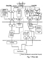
- FIG. 1 shows a conventional floating-point addition unit 100 having two concurrent pipeline paths, i.e., a short path 101 and a long path 102, configured to perform floating-point operations in parallel.
- the floating-point addition unit of FIG. 1 has potential speed advantages but also requires a comparatively complex hardware implementation for the dual concurrent pipeline paths. Short Path Long Path Operations Subtraction when the Subtraction when the difference in the exponent of difference in the exponent of two operands is zero or one two operands is greater than one, or addition
- each pipeline path is arranged to require a shift of the mantissa in only one direction.
- the short path is used for effective subtraction operations when the difference between the exponents of the two floating-point operands is 0 or 1.
- the long path is used for all addition operations and for subtraction operations when the exponent difference for the two floating-point operands is greater than 1. This is summarized in Table I.
- the mantissas are aligned by right shifting the smaller operand based on the exponent difference.
- An addition result in the long path may require rounding but no left shifting for post normalization is required because there will not be any leading zero.
- a subtraction result in the long path may require rounding and at most one left shift for post normalization because there will never be more than one leading zeros.
- Exponent Difference Mantissa Alignment Normalization Rounding of Result 0 Not required. Possibly required Not required. 1 Required Possibly required Possibly required
- a guard bit, a round bit, and/or a sticky bit, as described in the IEEE-754 Standard, are typically used to round the result of the floating point operation. Referring now to Table II, if the exponent difference is zero, the mantissas of the two operands do not need to be aligned. If the result of the mantissa subtraction is less than 1, a normalization step is performed using a normalization left shifter. No rounding of the result is required after the normalization step because the guard bit, the round bit, and the sticky bit, as described in the IEEE-754 Standard, are empty.
- the mantissas of the two operands need to be aligned by right shifting the mantissa of the smaller operand by one.
- a rounding step may also be required after mantissa subtraction because, with the right shifting, the guard bit may not be empty. If the guard bit has a value of one, a rounding operation needs to be performed to achieve an IEEE-754 compliant result.
- the rounding step in the short path is typically done by an incrementer.
- This incrementer is undesirable because it results in a delay through the short path being potentially greater than the delay through the long path.
- additional hardware e.g., logic gates
- the apparatus and method of the present invention operate to perform a floating-point operation involving at least two operands in floating-point representation.
- the apparatus comprises two concurrent data paths, a short path and a long path.
- the short path is used to produce a result of the floating-point operation if the floating-point operation is a subtract operation and the difference between the exponents of the two operands ("exponent difference") is 0, or if the floating-point operation is a subtract operation, the exponent difference is 1, and the mantissa of the operand with a larger exponent is within a predetermined number range.
- the long path is used to produce a result of the floating-point operation if the floating point operation is an addition operation, or if it is a subtraction operation and the exponent difference is larger than one, or if it is a subtract operation, the exponent difference is 1, and the mantissa of the operand with the larger exponent is within another predetermined number range.
- the short path does not require means such as an incrementer for post subtraction normalization.
- the present invention includes a floating-point adder system, method, and algorithm. Some details of a preferred implementation of the present invention are described in an article "1-Ghz HAL SPARC 64 Dual Floating-point Unit With RAS Features," by Ajay Naini, Atul Dhablania, Warren James, and Debjit Das Sarma. Proceedings of the 15 th IEEE Symposium on Computer Arithmetic, 11-13 June 2001. Vail, Colorado, pp. 173-183, which is incorporated by reference herein.
- FIG. 2 is a flow chart illustrating a process 200 of the present invention for performing an addition or subtraction operation on two floating-point operands.
- the process 200 comprises an alignment step 210 and three concurrent sub-processes, a short path process 230, a long path process 240, and a selection process 220.
- the alignment step 210 the two operands are received and are aligned with the IEEE double-precision format.
- the process 200 further comprises a result selection step 250 for selecting a result from the short path process 230 or the long path process 240 based on a determination of the selection process 220.
- the selection process determines whether to select a result produced by the short path process 230 or by the long path process 240 for the addition or subtraction operation based on the criteria set out in Table III. Referring to Table III, the result from the short path process 230 is selected at the result selection step 250 if:
- the result from the long path process 240 is selected at the result selection step 250 if:
- the selection process determines whether to select a result from either the short path process 230 or the long path process 240 according to the criteria set out in Table IV. Referring to Table IV, the result from the short path process 230 is selected at the result selection step 250 if:
- the result from the long path process 240 is selected at the result selection step 250 if:
- FIG. 2A illustrates in more detail the selection process 220 according to one embodiment of the present invention.
- the selection process 220 comprises a step 221 for determining whether the floating-point operation is an addition operation or subtract operation.
- the selection process 200 makes a decision to select the result from the long path process 240 and passes this decision to the result selection step 250.
- the selection process 200 proceeds to determine the exponent difference for the two operands at steps 223 and 225.
- the process 200 makes the decision to select the result from the long path process 240 and passes this decision to the result selection step 250.
- the process 200 makes a decision to select the result from the short path process 230 and passes this decision to the result selection step 250.
- the process 200 proceeds to determine, at step 227, whether the mantissa of the operand with the larger exponent is less than 1.5 (or not greater than 1.5 if the selection rule in Table IV is used). In response to the determination that the larger mantissa is less than 1.5 (or not greater than 1.5 if the selection rule in Table IV is used), the process 200 makes the decision to select the result from the short path process 230 and passes this decision to the result selection step 250.
- the process 200 makes the decision to select the result from the long path process 240 and passes this decision to the result selection step 250.
- the selection rule as set out in Table III is simpler to execute than the selection rule as set out in Table IV.
- the selection rule in Table III only the two MSB bits of the mantissa of the operand with the larger exponent needs to be examined at step 227 to determine if the mantissa has a value less than 1.5 (meaning that result from the short path should be selected), or not less than 1.5 (meaning that result from the long path should be selected).
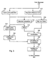
- FIG. 3 is a flow chart illustrating the short path process 230 in more detail.
- two sets of steps. are taken in parallel to each other, and both sets of steps is followed by a left shifting for normalization step 324.
- the first set of steps start with step 310 where the two least significant exponent bits of operand A is compared with the two least significant exponent bits of operand B.
- an align and swap step 314 is taken afterwards where the operand with the smaller exponent (based on the two least significant exponent bits) is right shifted by 1 bit in order to align the mantissas of the two operands, and the two operands may be swapped so that the operand with the smaller exponent will be subtracted from the operand with the larger exponent.
- a mantissa comparison step 316 is taken to determine which mantissa is larger, followed by a swap step 318 where the operands may be swapped so that the smaller mantissa will be subtracted from the larger mantissa.
- a mantissa subtraction step 320 is a mantissa subtraction step 320, where the mantissa of the smaller operand is subtracted from the mantissa of the larger operand.
- the second set of steps comprises a leading zero prediction step 312 for predicting leading zeros in a final result of the subtract step 320, and a leading zero counting step 322 for counting and encoding the predicted leading zeros.
- a leading zero prediction step 312 for predicting leading zeros in a final result of the subtract step 320
- a leading zero counting step 322 for counting and encoding the predicted leading zeros.
- an algorithm is used to generate two leading zero vectors, Z 1 and Z 2 .
- the leading zero vector Z 1 is generated assuming that the mantissa of A will be subtracted from the mantissa of B and the leading zero vector Z 2 is generated assuming that the mantissa of B will be subtracted from the mantissa of A.
- the second set of steps further comprises a leading zero vector selection step 315 for selecting, based on results from steps 310 and 316, where the larger operand is determined, the leading zero vector generated with the assumption that the mantissa of the smaller operand will be subtracted from the mantissa of the larger operand.
- the above prediction algorithm which does not use a full carry chain, generates the prediction vector Z 2 that has, at most, one too few leading zeros, as compared to the number of leading zeros in the final result of the subtraction step 320. Therefore, the short path process further comprises a leading zero correction step 330 for correcting this error.
- the leading zeros in the selected leading zero vector is counted and encoded at the leading zero counting step 322.
- the mantissa subtraction is computed at the subtraction step 320. Because steps 312, 315, and 322 anticipate the number of leading zeros and thus the amount of left shift for normalization , and are performed in parallel with the subtraction step 320, a left shifting for normalization step 324 can be carried out immediately after the subtraction step 320 in accordance with the anticipated amount of shift.
- a result from the subtraction step 320 is left shifted according to the number of leading zeros predicted.
- the leading zero correction step 330 follows the left shifting for normalization step 324 to correct any error resulted from the leading zero prediction algorithm for the leading zero prediction step 312.
- the short path does not require a rounding step because the result of the subtraction operation performed in the short path always has a mantissa value less than or equal to one.
- the minuend is in the range of (1, 1.5) and the one-bit shifted subtrahend is in the range of [0.5, 1) yielding a result that falls in the range of (0,1).
- the guard bit is moved to at least the least significant bit position (LSB). Therefore, no rounding in the short path is required.
- FIG. 4 is a flow chart showing the long path process 240 in more detail.
- both the lower order bits of e A - e B and the lower bits of e B - e A are calculated in parallel at steps 410a and 410b, respectively.
- the lower order bits of e A - e B such as the two least significant bits of e A - e B , is used to partially right shift the mantissa of operand B by 0, 1, 2, or 3 bits at step 412a, while a full result of e A - e B is being calculated in parallel at step 411a.
- the lower order bits of e B - e A such as the two least significant bits of e B - e A , is used to partially right shift the mantissa of operand A by 0, 1, 2, or 3 bits at step 412b, while a full result of e B - e A is being calculated in parallel at step 411b.
- a smaller operand between A and B is selected at step 414, and the partially right shifted smaller operand is selected at step 416.
- the partially right shifted smaller operand may be swapped with the other operand so that the smaller operand is in the subtrahend position for the subtract operation.
- Step 416 is followed by step 420 where the smaller operand may be further right shifted according to the full result of e A - e B or c B - e A , which ever is positive.
- rounding information is computed in parallel at step 428, which performs a rounding logic according to the IEEE-754 standard.
- step 428 mantissa addition or subtraction is performed at steps 424, and 426.
- the computation of A+B, A+B+1, and A+B+2 are required. This can be achieved using only two concurrent steps 424 and 426 to generate A+B and A+B+2, respectively, because A+B+1 can be derived from these two results and the derivation is done at step 430.
- a first level result selection is also done to select a result among the results of A+B, A+B+1, and A+B+2 for the long path process, and the selected result is normalized and/or rounded based on the rounding information from step 428.
- subtraction operations for an exponent difference of one and the mantissa of the larger operand having a magnitude value greater than or equal to 1.5 are performed in the long path.
- the mantissa of the smaller operand is aligned by right shifting. If the exponent difference is one and the mantissa of the larger operand has a value greater than 1.5, the subtraction is limited to a minuend in the range of [1.5,2) and subtrahend in the range [0.5,1) with a result falling in the range of (0.5, 2). Therefore, no post-addition right shifting in the long path is required and the potential single bit left shift may be handled during the first stage of the result selection step 430.
- FIG. 5 is a schematic block diagram showing an overall structure of a floating-point adder unit 500 that implements the process 200 described above.
- the floating-point adder unit 500 comprises an alignment module 510 that implements the alignment step 210 in the process 200.
- the alignment module 510 receives as inputs the operands A and B for addition or subtraction, and aligns the operands with the IEEE double precision format.
- the floating-point adder unit 500 has two concurrent pipelined paths, a short path and a long path.
- the floating-point adder unit 500 comprises an exponent difference by one predictor 514-1 coupled to the alignment module 510 for implementing step 310 of the process 200.
- the exponent difference by one predictor 514-1 determines whether the exponent difference for the two operands is zero by examining just the two least significant exponent bits of each operand.
- the floating-point adder unit 500 further comprises a first swap module 514 coupled to the alignment module 510 and to the exponent difference by one predictor 514-1.
- the first swap module 514 includes circuit elements that implements steps 314 in the process 200, i.e., in response to the determination by the exponent difference by one predictor 514-1 that the exponent difference for the operands A and B is not zero, the first swap module 514 aligns the mantissas of the two operands by right shifting the mantissa of the operand with the smaller exponent (determined by examining only the two least significant exponent bits of each operand) by one bit and swap the two operands if the operand with the smaller exponent happens to be at the minuend position.
- the floating-point adder unit 500 further comprises an operand comparison module 518-1 coupled to the alignment module 510, and a second swap module 518 coupled to the first swap module 514 and to the operand comparison module 518-1. If the exponent difference by one predictor 514-1 determines that the exponent difference for the two operands is zero, the operand comparison module 518-1 and the second swap module 518 responds by performing steps 316 and 318 in the process 200, i.e., the operand comparison module 518-1 compares the mantissas of the two operands to determine which operand is larger in value, and if the larger operand happens to be the subtrahend, the second swap module 518 swaps the operands so that the larger operand is moved to the minuend position.
- the floating-point adder unit 500 further comprises a leading zero predict module 512 coupled to the alignment module 510, and a select module 515 coupled to the exponent difference by one predictor 514-1 and the operand comparison module 518-1, and to the leading zero predict module 512.
- the leading zero predict module 512 performs step 312 of the process 200, and the select module 515 performs step 315 in the process 200.
- the leading zero predict module 512 includes conventional logic circuits configured to carry out the logic operations prescribed by the leading zero prediction algorithm for the leading zero prediction step 310 in the process 200, as discussed above.
- the floating-point adder unit 500 comprises an first adder 520 coupled to the second swap module in pipeline stage 1, a leading zero counter 522 coupled to the select module 515, and a left shifter 524 in the short path coupled to the first adder and the leading zero counter.
- the first adder 520 includes logic circuits configured to perform the mantissa subtraction step 320 in the process 200.
- the leading zero counter performs the leading zero counting step 322 in the process 200
- the left shifter 524 performs the left shifting for normalization step 324 in the process 200.
- the floating-point adder unit 500 comprises a leading zero correction module 530 coupled to the left shifter 524 in the pipeline stage 2.
- the leading zero correction module performs the leading zero correction step 330 in the process 200.
- the floating-point adder unit 500 comprises a second adder 511a and a third adder 511b, both being coupled to the selection and alignment module 510.
- the second adder 511a receives the operands A and B from the alignment module 510, and performs step 410a for calculating the lower order bits of e A - e B and step 411a for calculating the rest of the bits for the full result of e A - e B in the process 200.
- the third adder 51 1b receives the operands A and B from the alignment module 510, and performs step 410b for calculating the lower order bits of e B - e A and step 41 1b for calculating the rest of the bits for the full result of e B - e A in the process 200.
- the floating-point adder unit 500 further comprises a first right shifter 513a coupled to the alignment module 510 and to the second adder 511a, and a second right shifter 513b coupled to the selection and alignment module 510 and to the third adder 511b.
- the first right shifter 513a receives the operands A and B from the selection and alignment module 510, receives the lower order bits of e A - e B from the second adder 511a, and performs step 412a for partially right shifting the mantissa of operand B by 0, 1, 2, or 3 bits based on the lower order bits of e A - e B .
- the second right shifter 513a receives the operands A and B from the selection and alignment module 510, receives the lower order bits of e B - e A from the third adder 51 1b, and performs step 412b for partially right shifting the mantissa of operand A by 0, 1, 2, or 3 bits based on the lower order bits of e B - e A .
- the floating-point adder unit 500 comprises an operand selection module 517 coupled to the second adder 511 a and the third adder 511 b, and a select/swap module 516 coupled to the first right shifter 513a and the second right shifter 513b, and to the operand selection module 517.
- the operand selection module 517 performs step 414 in the process 200, i.e., the operand selection module selects between operands A and B a smaller operand based on the results of the second adder 511 a and/or the third adder 511b.
- the selection is output to the select/swap module 516, which performs step 416 in the process 200 by selecting between the partially right shifted mantissas of A and B the partially right shifted mantissa of the smaller operand.
- the select/swap module 516 swaps the two operands so that the smaller operand is moved to the subtrahend position.
- the floating-point adder unit 500 comprises a third right shifter 521 coupled to the operand selection module 514 and to the select/swap module 516, a 3to 2 Carry Save Adder (CSA) 523 coupled to the third right sifter 521, a fourth adder 525 coupled to the 3to2 CSA 523, and a fifth adder 526 coupled to the third right shifter 521.
- the third right shifter 521 performs the right shifting step 420 in the process 200 and shifts the partially shifted mantissa of the smaller operand based on the higher order bits of the result of the second adder 511a or the third adder 511b.
- the fourth adder 525 performs step 424 for computing A+B+2 in the process 200
- the fifth adder 526 performs step 426 for computing A+B in the process 200.
- the 3to2 CSA is used for the generation of A+B+2 because the LSB position is different for double and single precesion.
- the floating-point adder unit 500 further comprises a rounding logic module 528 coupled to the second right shifter 520.
- the rounding information including the LSB+1 bit, the LSB, the guard bit, the round bit and the sticky bit, as described in the IEEE-754 standard, is computed in parallel by the rounding logic module 528.
- the floating-point adder unit 500 comprises a first stage result selection module 531 coupled to the fourth and fifth adders 524 and 526, and to the rounding logic module 528.
- the first stage result selection module 531 performs the first stage result selection step 430 in the process 200.
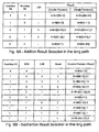
- FIG 6A is a table including result selection criteria and a rounding and normalization algorithm used by the first stage result selection module 531 for addition operations.
- FIG 6B is a table including result selection criteria and a rounding and normalization algorithm used by the first stage result selection module 531 for subtraction operations.
- rounding and normalization performed by the first stage result selection module are based on an overflow bit, which is one bit position higher than the most significant bit (MSB) of a selected result, a roundup bit, and the LSB.
- the roundup bit indicates a conditional increment of a pre-normalized result for performing IEEE-754 compliant rounding for all rounding modes, and is computed based on the rounding mode, sign, guard, round, sticky bits, and/or the overflow bit, according to the IEEE-754 standard.
- the floating-point adder unit 500 further comprises a selection logic module 540 coupled to the alignment module and including logic circuits configured to perform the selection process 220, i.e., to determine whether to select a result from the short path or the long path based on the selection criteria in Table III or IV.
- the floating-point adder unit 500 further comprises a result selection module 550 coupled to the left shifter 524 in the short path, the first stage result selection module 531 in the long path, and to the selection logic module 540.
- the result selection module 550 includes logic circuits configured to perform the result selection step 250 in the process 200, i.e., to select a result between results from the short path and the long path based a decision from the selection logic module 540.
- the present invention reduces the hardware cost by eliminating the incrementer in the pipeline stage 3 in the short path of the conventional adder unit illustrated in FIG 1.
- the present invention also eliminates the time delay associate with the rounding step in the short path of a conventional floating-point adder.
Landscapes
- Engineering & Computer Science (AREA)
- Physics & Mathematics (AREA)
- General Physics & Mathematics (AREA)
- Theoretical Computer Science (AREA)
- Computational Mathematics (AREA)
- Computing Systems (AREA)
- Mathematical Analysis (AREA)
- Mathematical Optimization (AREA)
- Pure & Applied Mathematics (AREA)
- General Engineering & Computer Science (AREA)
- Nonlinear Science (AREA)
- Complex Calculations (AREA)
Applications Claiming Priority (2)
| Application Number | Priority Date | Filing Date | Title |
|---|---|---|---|
| US922371 | 2001-08-02 | ||
| US09/922,371 US20030115236A1 (en) | 2001-06-07 | 2001-08-02 | Elimination of rounding step in the short path of a floating point adder |
Publications (1)
| Publication Number | Publication Date |
|---|---|
| EP1282034A2 true EP1282034A2 (fr) | 2003-02-05 |
Family
ID=25446938
Family Applications (1)
| Application Number | Title | Priority Date | Filing Date |
|---|---|---|---|
| EP02015111A Withdrawn EP1282034A2 (fr) | 2001-08-02 | 2002-07-05 | Elimination d'étape d'arrondi dans le trajet court d'un additioneur à virgule flottante |
Country Status (2)
| Country | Link |
|---|---|
| US (1) | US20030115236A1 (fr) |
| EP (1) | EP1282034A2 (fr) |
Cited By (1)
| Publication number | Priority date | Publication date | Assignee | Title |
|---|---|---|---|---|
| CN101359284B (zh) * | 2006-02-06 | 2011-05-11 | 威盛电子股份有限公司 | 处理数个不同数据格式的乘法累加单元及其方法 |
Families Citing this family (6)
| Publication number | Priority date | Publication date | Assignee | Title |
|---|---|---|---|---|
| US6941335B2 (en) * | 2001-11-29 | 2005-09-06 | International Business Machines Corporation | Random carry-in for floating-point operations |
| US7433911B2 (en) * | 2004-12-21 | 2008-10-07 | Arm Limited | Data processing apparatus and method for performing floating point addition |
| US8443029B2 (en) | 2007-03-01 | 2013-05-14 | International Business Machines Corporation | Round for reround mode in a decimal floating point instruction |
| US8392490B2 (en) * | 2008-02-18 | 2013-03-05 | International Business Machines Corporation | Identifying decimal floating point addition operations that do not require alignment, normalization or rounding |
| US9830129B2 (en) * | 2013-11-21 | 2017-11-28 | Samsung Electronics Co., Ltd. | High performance floating-point adder with full in-line denormal/subnormal support |
| GB2607364B (en) * | 2021-11-18 | 2023-05-24 | Imagination Tech Ltd | Floating point adder |
Family Cites Families (5)
| Publication number | Priority date | Publication date | Assignee | Title |
|---|---|---|---|---|
| US5010508A (en) * | 1989-02-14 | 1991-04-23 | Intel Corporation | Prenormalization for a floating-point adder |
| US4999803A (en) * | 1989-06-29 | 1991-03-12 | Digital Equipment Corporation | Floating point arithmetic system and method |
| GB2274730B (en) * | 1993-01-30 | 1997-05-28 | Motorola Inc | A mantissa addition system for a floating point adder |
| US5790445A (en) * | 1996-04-30 | 1998-08-04 | International Business Machines Corporation | Method and system for performing a high speed floating point add operation |
| US6085212A (en) * | 1997-10-23 | 2000-07-04 | Advanced Micro Devices, Inc. | Efficient method for performing close path subtraction in a floating point arithmetic unit |
-
2001
- 2001-08-02 US US09/922,371 patent/US20030115236A1/en not_active Abandoned
-
2002
- 2002-07-05 EP EP02015111A patent/EP1282034A2/fr not_active Withdrawn
Cited By (1)
| Publication number | Priority date | Publication date | Assignee | Title |
|---|---|---|---|---|
| CN101359284B (zh) * | 2006-02-06 | 2011-05-11 | 威盛电子股份有限公司 | 处理数个不同数据格式的乘法累加单元及其方法 |
Also Published As
| Publication number | Publication date |
|---|---|
| US20030115236A1 (en) | 2003-06-19 |
Similar Documents
| Publication | Publication Date | Title |
|---|---|---|
| US6763368B2 (en) | Method and apparatus for performing single-cycle addition or subtraction and comparison in redundant form arithmetic | |
| US8046399B1 (en) | Fused multiply-add rounding and unfused multiply-add rounding in a single multiply-add module | |
| KR100264962B1 (ko) | 결합된 선두 1 및 선두 제로 예상기 | |
| US8185570B2 (en) | Three-term input floating-point adder-subtractor | |
| US6996596B1 (en) | Floating-point processor with operating mode having improved accuracy and high performance | |
| US8239441B2 (en) | Leading zero estimation modification for unfused rounding catastrophic cancellation | |
| KR100241076B1 (ko) | 조정및정규화클래스를구비한부동소수점승산및누산장치 | |
| US5623435A (en) | Arithmetic unit capable of performing concurrent operations for high speed operation | |
| US20020129075A1 (en) | Apparatus and method of performing addition and rounding operation in parallel for floating-point arithmetic logical unit | |
| US5260889A (en) | Computation of sticky-bit in parallel with partial products in a floating point multiplier unit | |
| US7720899B2 (en) | Arithmetic operation unit, information processing apparatus and arithmetic operation method | |
| US7290023B2 (en) | High performance implementation of exponent adjustment in a floating point design | |
| JPH0520028A (ja) | 加減算のための浮動小数点演算装置の仮数部処理回路 | |
| US20030115236A1 (en) | Elimination of rounding step in the short path of a floating point adder | |
| US7016930B2 (en) | Apparatus and method for performing operations implemented by iterative execution of a recurrence equation | |
| US7206800B1 (en) | Overflow detection and clamping with parallel operand processing for fixed-point multipliers | |
| US6813628B2 (en) | Method and apparatus for performing equality comparison in redundant form arithmetic | |
| US20070038693A1 (en) | Method and Processor for Performing a Floating-Point Instruction Within a Processor | |
| US6571264B1 (en) | Floating-point arithmetic device | |
| US20030050948A1 (en) | Floating-point remainder computing unit, information processing apparatus and storage medium | |
| US20020147755A1 (en) | Method and apparatus for a fast comparison in redundant form arithmetic | |
| JP2003029960A (ja) | 浮動小数点加算器のショートパスにおける丸めステップの排除 | |
| US20040049528A1 (en) | Apparatus and method for adding multiple-bit binary-strings | |
| JP3257278B2 (ja) | 冗長なシフト数予測とシフト誤り補正を用いた正規化装置 | |
| JPH0635671A (ja) | 浮動小数点加減算装置 |
Legal Events
| Date | Code | Title | Description |
|---|---|---|---|
| PUAI | Public reference made under article 153(3) epc to a published international application that has entered the european phase |
Free format text: ORIGINAL CODE: 0009012 |
|
| AK | Designated contracting states |
Designated state(s): AT BE BG CH CY CZ DE DK EE ES FI FR GB GR IE IT LI LU MC NL PT SE SK TR |
|
| AX | Request for extension of the european patent |
Extension state: AL LT LV MK RO SI |
|
| STAA | Information on the status of an ep patent application or granted ep patent |
Free format text: STATUS: THE APPLICATION HAS BEEN WITHDRAWN |
|
| 18W | Application withdrawn |
Effective date: 20040825 |