EP1282086A2 - Banknotenprüfgerät - Google Patents
Banknotenprüfgerät Download PDFInfo
- Publication number
- EP1282086A2 EP1282086A2 EP02017625A EP02017625A EP1282086A2 EP 1282086 A2 EP1282086 A2 EP 1282086A2 EP 02017625 A EP02017625 A EP 02017625A EP 02017625 A EP02017625 A EP 02017625A EP 1282086 A2 EP1282086 A2 EP 1282086A2
- Authority
- EP
- European Patent Office
- Prior art keywords
- banknote
- checking device
- banknote checking
- support
- light source
- Prior art date
- Legal status (The legal status is an assumption and is not a legal conclusion. Google has not performed a legal analysis and makes no representation as to the accuracy of the status listed.)
- Withdrawn
Links
Images

Classifications
-
- G—PHYSICS
- G07—CHECKING-DEVICES
- G07D—HANDLING OF COINS OR VALUABLE PAPERS, e.g. TESTING, SORTING BY DENOMINATIONS, COUNTING, DISPENSING, CHANGING OR DEPOSITING
- G07D7/00—Testing specially adapted to determine the identity or genuineness of valuable papers or for segregating those which are unacceptable, e.g. banknotes that are alien to a currency
- G07D7/06—Testing specially adapted to determine the identity or genuineness of valuable papers or for segregating those which are unacceptable, e.g. banknotes that are alien to a currency using wave or particle radiation
- G07D7/12—Visible light, infrared or ultraviolet radiation
- G07D7/128—Viewing devices
Definitions
- the invention relates to a banknote checking device, the simply under the most diverse application and environmental conditions very easy and uncomplicated to use can be. It is especially for the Use in retail, also larger at individual checkouts Trading houses and supermarkets are suitable, though at such locations, a high time pressure for the review of banknotes. But it is also a Use in public transport vehicles or also possible in taxi companies.
- Banknotes used as the national currency were shown usually several different security features, such as watermarks, Review register, local limited printed micro fonts, Security threads in labeled and blank form.
- too Inks used when exposed to ultraviolet Light have a luminescent phenomenon.
- the latter security feature is common used for checking the authenticity of banknotes, because the test can be done relatively quickly. In however, this very security feature shows in the recent past often not the desired security on, since corresponding counterfeits occurred frequently are.
- DE 295 13 056 U1 describes a visual device Identification of banknotes described.
- This Device uses a magnifying element several differently focusing lenses. Becomes such a device to a specific one Microprinted printed position of a banknote, can the printed micro script visually and the authenticity of a banknote with higher security be checked because this security feature at counterfeit banknotes relatively difficult to recreate or can be imitated. Will the testing of Banknotes made with such a device, however, it is necessary to use the microprinted Area of a banknote related to the lenses to position and test in a particular Distance from this lens system, which is relatively time-consuming and for example in checkout a supermarket is almost impossible.
- Banknotes are often a sufficient security feature Dimensions can be mimicked or copied to it usually but not succeed, at least two or more of these security features present on these banknotes to be reproduced in such a way that evidence is provided Authenticity can be done with sufficient security.
- this object is achieved with a bank note checking device, having the features of claim 1, solved.
- Advantageous designs and Developments of the invention can with the in the subordinate and the subordinate claim 22 designated features can be achieved.
- the banknote checking device is used in in any case to check the security feature printed micro script an optical enlarging element or an arrangement of optical elements, with an enlargement of the printed micro script can be achieved. Furthermore are on a base body at least two orthogonal to each other aligned positioning elements available, the form a limit for a banknote pad. On these positioning elements, which are preferred as edge-shaped Stops are formed, can be tested Banknote created and on the banknote rest be positioned in a defined form. For testing the respective banknote is at least one light source, which are arranged below the banknote rest is used, at least during the test period can be switched on. Above the banknote rest a fixing element for banknotes is arranged, where the one optical magnifying element or an arrangement of several optical elements for enlargement arranged or integrated into the fixing element could be.
- Such a fixing element can be, for example be flat element that like one in DE 295 13 056 U1 described device is formed.
- These guides can be conveniently called grooves arranged parallel to each other be in which then a flat flat fixing element inserted and parallel to the grooves can be moved back and forth so that a variation the position of the optical elements for testing the micro script, as is the case with different ones State currencies may be required becomes possible.
- banknote pad aligns to the horizontal at an inclined angle, so that, for example, a cashier in the Sitting from their work place very easy and can quickly take the test.
- a Tilt angle between 10 and 60 ° from the horizontal be respected.
- the banknote pad can also be convex.
- the banknote support can at least in some areas, but also completely from a transparent for light Material exist, so that lighting with at least below the banknote rest a light source for optical testing of banknotes can be done.
- an inventive Banknote checker can in the area of the banknote support a variety of light exit openings be present that are temporarily covered or locked could be. These light exit openings can then be opened, depending on the national currency to be checked or be released.
- the predetermined breaking points can be easily removed.
- Such a cover can also be opaque Be slide on a banknote rest can be glued on and light exit openings by targeted removal of the opaque area Foil material can be obtained.
- Such a film can also be in two layers Be formed shape, with a layer of a for light transparent material and for example the top layer made of an opaque material consists.
- a single light source can be sufficient in the body below the banknote rest use and with this the entire area of Illuminate banknote pad. Should be advantageous however, a light source in the low voltage range up to use a maximum of 24 V.
- a xenon lamp for example, can be used as the white light source (White light diode) can be used.
- the light from the light source (s) can also be by means of reflectors towards the banknote rest or existing light exit openings directed there become.
- a housing or body can also be inside be provided with a reflective coating.
- the light sources use several LEDs, which then if possible arranged in relation to light exit openings are. It can also use flat diodes with which larger areas can be illuminated become.
- the banknote checking device can also work under certain conditions be advantageous on the banknote checking device according to the invention one inclined with respect to the banknote rest To provide a projection surface or a mirror. Thereby can project security features either on a screen or the mirror again in an enlarged form and the test easier respectively.
- the banknote checking device can be connected to a local electrical power supply network, if possible under Interposition of a suitable transformer, with which the commonly used mains voltage in the amount of approx. 220 V in the low voltage range can be transformed, connected.
- a suitable transformer with which the commonly used mains voltage in the amount of approx. 220 V in the low voltage range can be transformed, connected.
- the Energy supply via the electrical system. It exists but also the possibility of operating the one or more light sources required Electrical energy via electrical energy storage (Batteries, rechargeable batteries) which then advantageously arranged inside the base body are secure.
- At least one switching element should be available be with the one but also several Light sources can be switched on and off.
- each individual light source a single switching element may be present.
- Switching elements can be given certain selected groups of multiple light sources turn on together so that certain areas that are relevant for the selected national currency-specific Banknotes are illuminated, to check for different national currencies to enable and facilitate. This can may be necessary because of the different security features for the different national currencies are arranged differently on the banknotes.
- FIG. 1 of an inventive Banknote checking device 1 becomes a basic body 2 used, on which two orthogonal to each other aligned positioning elements 4 and 4 ' are the two corresponding limits of a banknote pad 3 form.
- These positioning elements 4 and 4 ' in the form of edges or patches Last can be formed, a defined Alignment and positioning one on the Banknote rest 3 placed, not shown here Banknote.
- the positioning element 4 ' can also be in different positions on the base body 2 can be attached to an adjustment of micro fonts on banknotes of different national currencies to enable and e.g. an alignment of a microscript printed on a banknote in relation to to the magnifying optical elements or arrangement several such elements 6 in one direction, that designated by the double arrow in Figure 1 is to enable.
- this positioning element 4 ' can be strip-shaped and on its underside with a contour or structural elements be provided, which then in the body 2 trained complementary contours or structures attached positively and / or non-positively can be.
- the positioning element 4 'can thus moved parallel to the positioning element 4 and in the desired one for each to be tested Banknotes specific position can be attached. So can the limitation of the banknote support 3 to adjust.
- two are parallel to each other on the base body 2 opposite guides 8 or corresponding conditions formed into which a fixing element 5 is inserted or has been inserted.
- this fixing element 5 is an enlarging arrangement integrated at least two plano-convex lenses, with the one printed on a banknote Microscript in an enlarged form visually recorded can be.
- the representation according to FIG. 1 clearly that the base body 2 and consequently the Banknote rest in relation to a horizontal one which the base body 2 can be parked in one Inclined at an angle and also the banknote rest 3 is convex.
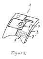
- the circular light outlet openings 7 to check a single one State currency arranged in a defined and known form become.
- a watermark or a review register can be checked and with the second, further down left Light exit opening 7, testing on the corresponding Supported microprint banknote printed become.
- the corresponding security features are illuminated not with at least one here shown light source. But there is also Possibility for each of the two light exit openings shown 7 a single separate light source, preferably used in the form of a light emitting diode. Of course, more can be done than this two light exit openings shown and if necessary multiple light sources can also be used.
- These light exit openings 7 'can for example perforated areas of an otherwise opaque Cover be for a particular State currency specifically removed and for the respective Banknotes then correspondingly arranged light exit openings 7 'form.
- a similar form can also already be used with the described in the general part of the description two-layer film made of a transparent and can consist of an opaque layer, be moved.
- the opaque one Layer that for the light exit openings 7 ' provided perforations is provided on the Arranged the top of such a film and this opaque layer can be used for a targeted Formation of light exit openings 7 'for national currency deducted specifically for certain banknotes and so the respective light exit openings 7 'created become.
Landscapes
- Health & Medical Sciences (AREA)
- General Health & Medical Sciences (AREA)
- Toxicology (AREA)
- Physics & Mathematics (AREA)
- General Physics & Mathematics (AREA)
- Inspection Of Paper Currency And Valuable Securities (AREA)
Abstract
Description
- Figur 1
- in schematischer und perspektivischer Darstellung ein Beispiel eines erfindungsgemäßen Banknotenprüfgerätes und
- Figur 2
- Beispiele für die Anordnung von Lichtaustrittsöffnungen auf einer Banknotenauflage eines erfindungsgemäßen Banknotenprüfgerätes.
Claims (23)
- Banknotenprüfgerät mit einem optischen Vergrößerungselement oder einer vergrößernden Anordnung optischer Elemente (6),
bei dem mindestens zwei orthogonal zueinander ausgerichtete Positionierelemente (4, 4') an einem Grundkörper (2) eine Begrenzung für eine Banknotenauflage (3) bilden;
unterhalb der Banknotenauflage (3) mindestens eine Lichtquelle und oberhalb der Banknotenauflage (3) ein Fixierelement (5) für Banknoten angeordnet sind;
und
das optische Vergrößerungselement oder die Anordnung optischer Elemente (6) am Fixierelement (5) angeordnet oder in das Fixierelement (5) integriert ist/sind. - Banknotenprüfgerät nach Anspruch 1,
dadurch gekennzeichnet, dass ein flächiges Fixierelement (5) in Führungen (8) eines Grundkörpers (2) in einem Abstand zur Banknotenauflage (3) gehalten ist. - Banknotenprüfgerät nach Anspruch 1 oder 2,
dadurch gekennzeichnet, dass die Führungen (8) parallel zueinander angeordnet und nutenförmig ausgebildet sind. - Banknotenprüfgerät nach einem der Ansprüche 1 bis 3, dadurch gekennzeichnet, dass die Banknotenauflage (3) in einem Winkel zwischen 10 bis 60° gegenüber der Horizontalen geneigt ist.
- Banknotenprüfgerät nach einem der Ansprüche 1 bis 4, dadurch gekennzeichnet, dass die Banknotenauflage (3) konvex gewölbt ist.
- Banknotenprüfgerät nach einem der Ansprüche 1 bis 5, dadurch gekennzeichnet, dass die Banknotenauflage (3) zumindest bereichsweise aus einem transparenten Material gebildet ist.
- Banknotenprüfgerät nach einem der Ansprüche 1 bis 6, dadurch gekennzeichnet, dass innerhalb des Bereiches der Banknotenauflage (3) mindestens zwie diskret angeordnete Lichtaustritts-öffnungen (7, 7') vorhanden sind.
- Banknotenprüfgerät nach Anspruch 7,
dadurch gekennzeichnet dass die Lichtaustritts-öffnungen (7, 7') temporär abgedeckt oder verschlossen sind. - Banknotenprüfgerät nach einem der Ansprüche 1 bis 8, dadurch gekennzeichnet, dass die Banknotenauflage (3) mit einer Abdeckung, in der diskret angeordnete Lichtaustrittsöffnungen (7, 7') vorhanden sind, überdeckt ist.
- Banknotenprüfgerät nach Anspruch 9,
dadurch gekennzeichnet, dass die Abdeckung eine lichtundurchlässige Folie ist. - Banknotenprüfgerät nach einem der Ansprüche 1
bis 10, dadurch gekennzeichnet, dass die mindestens eine Lichtquelle eine Weißlichtquelle ist. - Banknotenprüfgerät nach einem der Ansprüche 1
bis 11, dadurch gekennzeichnet, dass eine zweite Lichtquelle Licht im Wellenlängenbereich zwischen 550 bis 700 nm abstrahlt. - Banknotenprüfgerät nach Anspruch 11,
dadurch gekennzeichnet dass die Weißlichtquelle eine Xenonlampe ist. - Banknotenprüfgerät nach Anspruch 12,
dadurch gekennzeichnet, dass die Lichtquellen Leuchtdioden oder Flachdioden sind. - Banknotenprüfgerät nach einem der Ansprüche 1
bis 14, dadurch gekennzeichnet, dass das optische Vergrößerungselement (6) eine Lupe oder Leseleiste ist. - Banknotenprüfgerät nach Anspruch 15,
dadurch gekennzeichnet, dass das optische Vergrößerungselement (6) eine Standardvergrößerung größer als 10 aufweist. - Banknotenprüfgerät nach einem der Ansprüche 1
bis 14, dadurch gekennzeichnet, dass die Anordnung optischer Elemente (6) aus mindestens zwei Linsen gebildet ist. - Banknotenprüfgerät nach Anspruch 17,
dadurch gekennzeichnet, dass die zwei Linsen plankonvexe Linsen sind. - Banknotenprüfgerät nach Anspruch 17,
dadurch gekennzeichnet, dass die Linsen Fresnellinsen sind. - Banknotenprüfgerät nach einem der Ansprüche 17 bis 19, dadurch gekennzeichnet, dass ein Positionierelement (4') parallel zum anderen Positionierelement (4) verschiebbar und in unterschiedlichen Positionen banknotenspezifisch form- und/oder kraftschlüssig am Grundkörper (2) befestigbar ist.
- Banknotenprüfgerät nach einem der Ansprüche 1 bis 20, dadurch gekennzeichnet, dass eine in einem Winkel zur Banknotenauflage (3) geneigte Projektionsfläche oder ein Spiegel vorhanden ist.
- Banknotenprüfgerät nach einem der Ansprüche 1 bis 21, dadurch gekennzeichnet, dass mindestens ein Schaltelement zum Ein- und Ausschalten der Lichtquelle(n) und/oder für staatswährungsspezifische Gruppen mehrerer Lichtquellen vorhanden ist.
- Verfahren zur Prüfung der Echtheit von Banknoten mit einem Banknotenprüfgerät nach einem der Ansprüche 1 bis 22,
dadurch gekennzeichnet, dass an einer Banknote gleichzeitig mindestens zwei unterschiedliche Sicherheitsmerkmale optisch überprüft werden.
Applications Claiming Priority (2)
| Application Number | Priority Date | Filing Date | Title |
|---|---|---|---|
| DE10138939 | 2001-08-04 | ||
| DE10138939A DE10138939A1 (de) | 2001-08-04 | 2001-08-04 | Banknotenprüfgerät |
Publications (2)
| Publication Number | Publication Date |
|---|---|
| EP1282086A2 true EP1282086A2 (de) | 2003-02-05 |
| EP1282086A3 EP1282086A3 (de) | 2004-05-06 |
Family
ID=7694796
Family Applications (1)
| Application Number | Title | Priority Date | Filing Date |
|---|---|---|---|
| EP02017625A Withdrawn EP1282086A3 (de) | 2001-08-04 | 2002-08-03 | Banknotenprüfgerät |
Country Status (2)
| Country | Link |
|---|---|
| EP (1) | EP1282086A3 (de) |
| DE (1) | DE10138939A1 (de) |
Cited By (1)
| Publication number | Priority date | Publication date | Assignee | Title |
|---|---|---|---|---|
| WO2021239390A1 (de) * | 2020-05-29 | 2021-12-02 | Bundesdruckerei Gmbh | Dokumentenlesegerät mit fixierungsklemme |
Family Cites Families (6)
| Publication number | Priority date | Publication date | Assignee | Title |
|---|---|---|---|---|
| FR2382060A1 (fr) * | 1977-02-25 | 1978-09-22 | France Esthetique Diffusion | Dispositif pour l'observation de documents, notamment afin de determiner s'ils ont ete falsifies ou d'effectuer une comparaison entre documents |
| DE9403794U1 (de) * | 1994-03-07 | 1994-05-19 | Czewo Plast Kunststofftechnik Gmbh, 93073 Neutraubling | Wertpapier-Prüfgerät |
| DE9308547U1 (de) * | 1993-06-01 | 1993-08-05 | Franke, Gernot S., 10625 Berlin | Banknotenprüfgerät |
| DE9308828U1 (de) * | 1993-06-14 | 1993-08-19 | Mastnak, Dirk, 86316 Friedberg | Wertpapier-Testgerät |
| DE9320841U1 (de) * | 1993-08-30 | 1995-06-22 | Schneeweiss, Roman, 10707 Berlin | Vorrichtung zum Erkennen von auf Banknoten aufgedruckten Mikroschriften |
| AU6269699A (en) * | 1998-09-29 | 2000-04-17 | Angstrom Technologies, Inc. | First-order authentication system |
-
2001
- 2001-08-04 DE DE10138939A patent/DE10138939A1/de not_active Withdrawn
-
2002
- 2002-08-03 EP EP02017625A patent/EP1282086A3/de not_active Withdrawn
Cited By (2)
| Publication number | Priority date | Publication date | Assignee | Title |
|---|---|---|---|---|
| WO2021239390A1 (de) * | 2020-05-29 | 2021-12-02 | Bundesdruckerei Gmbh | Dokumentenlesegerät mit fixierungsklemme |
| EP4158605A1 (de) * | 2020-05-29 | 2023-04-05 | Bundesdruckerei GmbH | Dokumentenlesegerät mit fixierungsklemme |
Also Published As
| Publication number | Publication date |
|---|---|
| EP1282086A3 (de) | 2004-05-06 |
| DE10138939A1 (de) | 2003-02-13 |
Similar Documents
| Publication | Publication Date | Title |
|---|---|---|
| EP1827866B1 (de) | Sicherheitsdokument mit lichtquelle und lichtverarbeitungsvorrichtung | |
| EP1983473B1 (de) | Datenträger mit Kennzeichnungen | |
| DE10312708B4 (de) | Retroreflektor | |
| EP1676157B9 (de) | Verfahren zum Erzeugen eines ebenen oder gekrümmten Gitterbildes | |
| DE69519590T2 (de) | Sichtgerät und verfahren zum simultanen ermitteln der farbwechselcharakteristika eines optisch variablen gegenstandes | |
| DE19924750A1 (de) | Leseanordnung für Informationsstreifen mit optisch kodierter Information | |
| EP1527424A2 (de) | Vorrichtung und verfahren zur bearbeitung von wertdokumenten | |
| EP3009964A1 (de) | Datenträger mit einer lichtquelle und einem graphischen element | |
| DE112016001961T5 (de) | Hervorhebung, gegenstand, vorlageplatte und verfahren zum erzeugen der vorlageplatte | |
| EP2029371B1 (de) | Refraktives durchsichtssicherheitselement | |
| EP3513984A1 (de) | Sicherheitselement mit lumineszenz-motivbereich | |
| DE102012109064A1 (de) | Lichtsteuerfolie, die mit einem Sicherheitsmerkmal ausgebildet ist | |
| DE10127981C1 (de) | Diffraktives Sicherheitselement | |
| DE2428975A1 (de) | Einrichtung zur halbautomatischen visuellen pruefung von banknoten oder dgl. auf echtheit | |
| DE102015226602A1 (de) | Verfahren zum Herstellen eines Sicherheitsdokumentes und Sicherheitsdokument | |
| WO2003085608A2 (de) | Vorrichtung zur verifikation von sicherheitsmerkmalen | |
| EP1282086A2 (de) | Banknotenprüfgerät | |
| DE60118472T2 (de) | Vorrichtung zum Schutz von Dokumenten vor Verfälschung | |
| EP1490840B1 (de) | Vorrichtung zur verifikation von sicherheitsmerkmalen | |
| EP2619712B1 (de) | Verfahren und vorrichtung zur erkennung und/oder beurteilung dreidimensionaler erhabener strukturen auf einer oberfläche eines dokuments | |
| EP3513248B1 (de) | Erfassungsvorrichtung zum erfassen eines gesichtsbildes einer person | |
| DE102021002214A1 (de) | Sicherheitsmerkmal für ein Wertdokument, Wertdokument und Verfahren zur Herstellung eines Sicherheitsmerkmals | |
| EP1496479A1 (de) | Lesegerät zur automatischen Prüfung der Echtheit von Dokumenten | |
| DE102020209013A1 (de) | Laminationskörper mit beleuchtetem Sicherheitsmerkmal und Verfahren zu dessen Verifikation | |
| DE60021702T2 (de) | Vorrichtung zum Fälschungsschutz von Dokumenten |
Legal Events
| Date | Code | Title | Description |
|---|---|---|---|
| PUAI | Public reference made under article 153(3) epc to a published international application that has entered the european phase |
Free format text: ORIGINAL CODE: 0009012 |
|
| AK | Designated contracting states |
Designated state(s): AT BE BG CH CY CZ DE DK EE ES FI FR GB GR IE IT LI LU MC NL PT SE SK TR |
|
| AX | Request for extension of the european patent |
Extension state: AL LT LV MK RO SI |
|
| PUAL | Search report despatched |
Free format text: ORIGINAL CODE: 0009013 |
|
| AK | Designated contracting states |
Kind code of ref document: A3 Designated state(s): AT BE BG CH CY CZ DE DK EE ES FI FR GB GR IE IT LI LU MC NL PT SE SK TR |
|
| AX | Request for extension of the european patent |
Extension state: AL LT LV MK RO SI |
|
| 17P | Request for examination filed |
Effective date: 20041105 |
|
| AKX | Designation fees paid |
Designated state(s): AT BE BG CH CY CZ DE DK EE ES FI FR GB GR IE IT LI LU MC NL PT SE SK TR |
|
| 17Q | First examination report despatched |
Effective date: 20050310 |
|
| STAA | Information on the status of an ep patent application or granted ep patent |
Free format text: STATUS: THE APPLICATION IS DEEMED TO BE WITHDRAWN |
|
| 18D | Application deemed to be withdrawn |
Effective date: 20051122 |