EP1282152A2 - Hélice pour électrode à double couche pour lampe à décharge à haute intensité et méthode de fabrication de l'hélice pour électrode - Google Patents
Hélice pour électrode à double couche pour lampe à décharge à haute intensité et méthode de fabrication de l'hélice pour électrode Download PDFInfo
- Publication number
- EP1282152A2 EP1282152A2 EP02016959A EP02016959A EP1282152A2 EP 1282152 A2 EP1282152 A2 EP 1282152A2 EP 02016959 A EP02016959 A EP 02016959A EP 02016959 A EP02016959 A EP 02016959A EP 1282152 A2 EP1282152 A2 EP 1282152A2
- Authority
- EP
- European Patent Office
- Prior art keywords
- wire
- coil
- turn
- helical groove
- electrode
- Prior art date
- Legal status (The legal status is an assumption and is not a legal conclusion. Google has not performed a legal analysis and makes no representation as to the accuracy of the status listed.)
- Withdrawn
Links
Images


Classifications
-
- H—ELECTRICITY
- H01—ELECTRIC ELEMENTS
- H01J—ELECTRIC DISCHARGE TUBES OR DISCHARGE LAMPS
- H01J61/00—Gas-discharge or vapour-discharge lamps
- H01J61/02—Details
- H01J61/04—Electrodes; Screens; Shields
-
- H—ELECTRICITY
- H01—ELECTRIC ELEMENTS
- H01J—ELECTRIC DISCHARGE TUBES OR DISCHARGE LAMPS
- H01J9/00—Apparatus or processes specially adapted for the manufacture, installation, removal, maintenance of electric discharge tubes, discharge lamps, or parts thereof; Recovery of material from discharge tubes or lamps
- H01J9/02—Manufacture of electrodes or electrode systems
-
- H—ELECTRICITY
- H01—ELECTRIC ELEMENTS
- H01J—ELECTRIC DISCHARGE TUBES OR DISCHARGE LAMPS
- H01J61/00—Gas-discharge or vapour-discharge lamps
- H01J61/02—Details
- H01J61/04—Electrodes; Screens; Shields
- H01J61/06—Main electrodes
- H01J61/073—Main electrodes for high-pressure discharge lamps
- H01J61/0732—Main electrodes for high-pressure discharge lamps characterised by the construction of the electrode
-
- Y—GENERAL TAGGING OF NEW TECHNOLOGICAL DEVELOPMENTS; GENERAL TAGGING OF CROSS-SECTIONAL TECHNOLOGIES SPANNING OVER SEVERAL SECTIONS OF THE IPC; TECHNICAL SUBJECTS COVERED BY FORMER USPC CROSS-REFERENCE ART COLLECTIONS [XRACs] AND DIGESTS
- Y10—TECHNICAL SUBJECTS COVERED BY FORMER USPC
- Y10T—TECHNICAL SUBJECTS COVERED BY FORMER US CLASSIFICATION
- Y10T29/00—Metal working
- Y10T29/49—Method of mechanical manufacture
- Y10T29/49002—Electrical device making
Definitions
- the present invention is directed to an electrode coil for a high intensity discharge (HID) lamp and to a method of making an electrode coil for a HID lamp.
- HID high intensity discharge
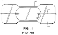
- a conventional HID lamp includes a tube 10 with two electrode coils 12 therein that are typically placed at opposing ends of tube 10.
- Tube 10 is filled with an appropriate gas and fill material, and sealed.
- Each electrode coil 12 includes a tungsten shank 14 with a tungsten wire coil 16 adjacent to a free end of tungsten shank 14 inside tube 10.
- Electrode coil 12 has been conventionally made with a coiled coil or by back winding tungsten wire to form a second layer of wire wound in a direction opposite to the winding direction of the first layer. These manufacturing methods have not proven entirely satisfactory.
- the coiled coil method includes the steps of winding a primary tungsten wire around a primary tungsten mandrel and then winding the coiled wire and primary mandrel around a secondary molybdenum mandrel.
- the coiled coil is heat-treated, cut to length, and heat-treated again.
- the secondary molybdenum mandrel is dissolved in acid and replaced with a tungsten shank.
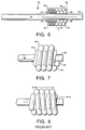
- An example of a coiled coil electrode coil is shown in Figure 2.
- the coiled coil method is generally cost effective because the manufacturing equipment is largely automated. However, the insertion of the tungsten shank can cause the primary tungsten mandrel to crack, which is a basis for rejecting the electrode coil.
- the back winding method includes the step of winding a tungsten wire around a retractable steel pin. After a predetermined number of turns or distance, the winding direction is reversed (for example, from left-to-right to right-to-left) and the wire is wound back over itself to form a second layer. Subsequently, several turns of the first layer may be left exposed, the steel pin removed, the coil oriented properly, and the tungsten shank inserted.
- An example of a back wound electrode coil is shown in Figure 3.
- the back winding method produces fewer problems than the coiled coil method when the tungsten shank is inserted, the back wound coil does not hold its shape well. Moreover, the process is more labor intensive as the asymmetrical coil must be oriented properly on the tungsten shank. The orientation of the coil takes additional time and these machines quickly reach capacity limits.
- U.S. Patent 4,105,908 discloses a back wound coiled coil electrode.
- a coil wrapped around a primary mandrel is wrapped around a secondary mandrel and back wound over itself to form a two-layer coiled coil, such as shown in Figure 4.
- manufacture of this electrode coil enjoys the problems of both the above-noted methods.
- U.S. Patent 2,523,033 is not related to the manufacture of electrode coils, but is of general interest because it discloses a double layer coil in a lamp.
- the lamp includes a filament that expands and contracts axially during use.
- a spring portion of the filament absorbs the stress of elongation and contraction.
- an in-lead 18 for the spring is thicker than filament 20 and is connected to filament 20 by butt-welding 22 the ends of the small diameter filament 20 to the large diameter in-lead 18.
- a first layer of wire 24 is wound around filament 20.
- the wire 24 has a diameter equal to the difference between the radii of filament 20 and in-lead 18.
- a second layer of wire 26 is screwed onto first layer 24 and onto in-lead 18. The combination of first and second layers of wire 24 and 26 reinforces butt-weld 22 by absorbing some of the mechanical strain.
- An object of the present invention is to provide a novel method of making an electrode coil for a HID lamp that avoids the problems of the prior art, specifically the problem of orienting the coil for insertion of the tungsten shank.
- a further object of the present invention is to provide a novel method of making an electrode coil for a HID lamp in which two overlapping wires are wrapped in the same direction on a mandrel so that the second wire is entirely within a helical groove on an exterior of the first wire and in which the two coils formed by the first and second wires are generally the same length.
- a yet further object of the present invention is to provide a novel method of making an electrode coil for a HID lamp including the steps of closely wrapping a first wire around a mandrel in a first direction to form a first coil with a helical groove on an exterior surface, closely wrapping a second wire in the first direction in the helical groove to form a second coil, where first and last turns of the second wire touch the first and last turns of the first wire, respectively, and dissolving the mandrel and replacing it with a tungsten core so that a free end of the tungsten core is adjacent to but spaced from a corresponding end of the first coil.
- Another object of the present invention is to provide a novel electrode coil for a HID lamp that avoids the problems of the prior art.
- Yet another object of the present invention is to provide a novel electrode coil for a HID lamp with two overlapping wires that are wrapped in the same direction so that the second wire is entirely within a helical groove on an exterior of the first wire and in which the two coils formed by the two wires are generally the same length.
- Still another object of the present invention is to provide a novel electrode coil for a HID lamp with a first wire closely wrapped in a first direction to form a first coil with a helical groove on an exterior surface, a second wire closely wrapped in the first direction in the helical groove to form a second coil, and a tungsten core with a free end adjacent to but spaced from a corresponding end of the first coil, where first and last turns of the second wire touch the first and last turns of the first wire, respectively.
- the present invention provides a more stable layer of coils during manufacture by front winding, instead of back winding, the layers of wire. That is, two lengths of wire are wound, one atop the other, in the same direction on a mandrel. This means that the second layer of wire is entirely within a helical groove on the exterior surface of the first layer of wire. This arrangement is particularly stable and permits more rapid insertion of the shank after removal of the mandrel.
- an embodiment of the present invention is an electrode coil for a HID lamp.
- the electrode coil 30 may include a tungsten core 32 with a free end 34 adapted to be placed in a HID tube.
- a first wire 36 is wrapped on tungsten core 32 in a first direction (for example, left to right, as shown by direction "A" in Figure 6) with each turn 38 of first wire 36 touching at least one other turn 38 of first wire 36.
- First wire 36 forms a first coil 40 that has an exterior surface with a helical groove therein.
- Free end 34 of tungsten core 32 is adjacent to but spaced from a corresponding end 42 of first coil 40, with an exterior of tungsten core 32 touching an interior of first coil 40.
- a "turn" of wire extends once around the mandrel.
- a second wire 46 is wrapped in the first direction directly on first wire 36 entirely in the helical groove in the exterior of first coil 40.
- Second wire 46 may be second length of wire separate from first wire 36.
- Second wire 46 forms second coil 48 whose interior touches the exterior of first coil 40.
- First coil 40 and second coil 48 may have substantially the same length; that is, a first turn of second wire 46 may touch a first turn of first wire 36 and a last turn of second wire 46 may touch a last turn of first wire 36, such as shown in Figure 6.
- Each turn 50 of second wire 46 may touch two turns 38 of first wire 36 and at least one other turn 50 of second wire 46.
- the method of making the electrode coil of Figure 6 may include the steps of closely wrapping first wire 36 around a mandrel (not shown, but is similar in size and shape to shank 32) in a first direction to form first coil 40 with a helical groove on an exterior surface. Thereafter, second wire 46 is closely wrapped in the first direction in the helical groove to form second coil 48, where a first turn of second wire 46 touches a first turn of first wire 36 and a last turn of second wire 46 touches a last turn of first wire 36. The mandrel is then removed and replaced with tungsten core 32 so that free end 34 of tungsten core 32 is adjacent to but spaced from corresponding end 42 of first coil 40. After wrapping second wire 46 and before replacing the mandrel, first and second coils 40 and 48 may be heat-treated, cut to a desired length, and heat-treated again.
- second coil 48 fits into the helical groove in the exterior of first coil 40 over an entire length of second coil 48.
- the lower layer of wire wound in direction "A” periodically is crossed by the upper layer of wire wound in direction "B” so that an entire length of the upper layer of wire is not in the helical groove in the exterior of the lower layer.
- the present invention provides the advantage that the two layers of coiled wire are substantially more stable than the two layers of coiled wire in the prior art.
- a more stable coiled wire is easier to handle and allows the tungsten core to be more easily inserted into the position vacated by the mandrel during manufacture. This stability decreases production time and reduces the number of rejected electrode coils.
- second wire 46 may have the same length as the helical groove, and first and second wires 36, 46 may both be tungsten wires with the same diameter.
- First wire 36 may be attached to tungsten core 32 to discourage unraveling and second wire 46 may be attached to first wire 36 for the same purpose.
- the ends of the first and second wires may be flattened.
- the mandrel may be removed conventionally, such as by dissolving in acid.
Landscapes
- Engineering & Computer Science (AREA)
- Manufacturing & Machinery (AREA)
- Discharge Lamp (AREA)
- Wire Processing (AREA)
Applications Claiming Priority (2)
| Application Number | Priority Date | Filing Date | Title |
|---|---|---|---|
| US921039 | 2001-08-02 | ||
| US09/921,039 US6853119B2 (en) | 2001-08-02 | 2001-08-02 | Double layer electrode coil for a HID lamp and method of making the electrode coil |
Publications (2)
| Publication Number | Publication Date |
|---|---|
| EP1282152A2 true EP1282152A2 (fr) | 2003-02-05 |
| EP1282152A3 EP1282152A3 (fr) | 2004-02-11 |
Family
ID=25444830
Family Applications (1)
| Application Number | Title | Priority Date | Filing Date |
|---|---|---|---|
| EP02016959A Withdrawn EP1282152A3 (fr) | 2001-08-02 | 2002-08-01 | Hélice pour électrode à double couche pour lampe à décharge à haute intensité et méthode de fabrication de l'hélice pour électrode |
Country Status (6)
| Country | Link |
|---|---|
| US (2) | US6853119B2 (fr) |
| EP (1) | EP1282152A3 (fr) |
| JP (1) | JP2003077391A (fr) |
| KR (1) | KR20030011681A (fr) |
| CN (1) | CN1407581A (fr) |
| CA (1) | CA2387331A1 (fr) |
Families Citing this family (5)
| Publication number | Priority date | Publication date | Assignee | Title |
|---|---|---|---|---|
| JP4892807B2 (ja) * | 2001-09-26 | 2012-03-07 | 岩崎電気株式会社 | 金属蒸気放電灯及びその製造方法 |
| CN100401448C (zh) * | 2003-10-29 | 2008-07-09 | 上海轻工业研究所有限公司 | 电极自动绕制装置及其方法 |
| KR100611033B1 (ko) * | 2004-08-10 | 2006-08-10 | 주식회사 뉴파워 프라즈마 | 코일 안테나를 갖는 형광 램프 및 이를 이용한 면광원 장치 |
| JP4840456B2 (ja) * | 2009-02-06 | 2011-12-21 | ウシオ電機株式会社 | 高圧放電ランプ |
| CN111725039B (zh) * | 2019-03-20 | 2023-03-31 | 上海亚尔精密零件制造有限公司 | 一种大功率气体放电灯电极弹簧的制造方法 |
Family Cites Families (12)
| Publication number | Priority date | Publication date | Assignee | Title |
|---|---|---|---|---|
| US2523033A (en) | 1949-12-16 | 1950-09-19 | Gen Electric | Electric radiant energy device |
| JPS541110B2 (fr) | 1973-11-30 | 1979-01-20 | ||
| NL175771B (nl) * | 1975-06-20 | 1984-07-16 | Philips Nv | Hogedrukgasontladingslamp en een werkwijze voor de vervaardiging hiervan. |
| US4105908A (en) | 1976-04-30 | 1978-08-08 | General Electric Company | Metal halide lamp having open tungsten coil electrodes |
| JPS5367972A (en) * | 1976-11-30 | 1978-06-16 | Mitsubishi Electric Corp | Electrode for elctric discharge lamp |
| JPS5641666A (en) * | 1979-09-13 | 1981-04-18 | Mitsubishi Electric Corp | Electrode for discharge lamp |
| US4334628A (en) * | 1980-11-21 | 1982-06-15 | Gte Laboratories Incorporated | Vacuum-tight assembly |
| JPS59171447A (ja) * | 1983-03-18 | 1984-09-27 | Mitsubishi Electric Corp | 放電灯用電極 |
| US5357167A (en) | 1992-07-08 | 1994-10-18 | General Electric Company | High pressure discharge lamp with a thermally improved anode |
| JPH1092377A (ja) * | 1996-09-17 | 1998-04-10 | Toshiba Lighting & Technol Corp | 放電灯用電極構体、その製造方法及びその電極構体を用いた放電灯 |
| JP3324584B2 (ja) | 1999-10-20 | 2002-09-17 | 松下電器産業株式会社 | 放電灯の製造方法 |
| JP3339580B2 (ja) * | 2000-04-18 | 2002-10-28 | 松下電器産業株式会社 | 高圧放電ランプの製造方法、及び高圧放電ランプ用電極の製造方法 |
-
2001
- 2001-08-02 US US09/921,039 patent/US6853119B2/en not_active Expired - Fee Related
-
2002
- 2002-05-24 CA CA002387331A patent/CA2387331A1/fr not_active Abandoned
- 2002-07-30 KR KR1020020044877A patent/KR20030011681A/ko not_active Withdrawn
- 2002-08-01 JP JP2002224607A patent/JP2003077391A/ja active Pending
- 2002-08-01 EP EP02016959A patent/EP1282152A3/fr not_active Withdrawn
- 2002-08-02 CN CN02127850A patent/CN1407581A/zh active Pending
-
2003
- 2003-09-23 US US10/668,822 patent/US20040055137A1/en not_active Abandoned
Also Published As
| Publication number | Publication date |
|---|---|
| US20040055137A1 (en) | 2004-03-25 |
| US20030025434A1 (en) | 2003-02-06 |
| KR20030011681A (ko) | 2003-02-11 |
| CA2387331A1 (fr) | 2003-02-02 |
| US6853119B2 (en) | 2005-02-08 |
| JP2003077391A (ja) | 2003-03-14 |
| EP1282152A3 (fr) | 2004-02-11 |
| CN1407581A (zh) | 2003-04-02 |
Similar Documents
| Publication | Publication Date | Title |
|---|---|---|
| EP0115921B1 (fr) | Lampe à déchargeà haute pression | |
| US6853119B2 (en) | Double layer electrode coil for a HID lamp and method of making the electrode coil | |
| US20020135302A1 (en) | Halogen incandescent lamp and a lighting apparatus using the lamp | |
| EP0209947A1 (fr) | Lampe à décharge à gaz à haute pression | |
| EP0209199B1 (fr) | Lampe à décharge à haute pression | |
| US4783611A (en) | High-pressure gas discharge lamp with electrodes having double layer coil | |
| HU193407B (en) | High-pressure gas dischage lamp with improved electrode | |
| EP0700070A2 (fr) | Cathode pour lampe à décharge haute intensité | |
| US4506187A (en) | Lamp filament structure, and method of its manufacture | |
| US5729081A (en) | Electrode coil for discharge lamps and method for producing such an electrode coil | |
| EP0708977B1 (fr) | Lampe a decharge haute pression | |
| US4179636A (en) | Electric incandescent lamp | |
| US5962972A (en) | Electric incandescent lamp | |
| US20140111080A1 (en) | Method for producing a winding for producing electrodes for discharge lamps, winding properties in electrodes for discharge lamps and method for producing an electrode for discharge lamps | |
| EP0343721A1 (fr) | Lampe à incandescence électrique | |
| GB2100506A (en) | An incandescent lamp coil | |
| US3588579A (en) | Electric lamp filament having a coiled-coil body portion with oriented offset legs,and method of manufacture | |
| JP5325527B2 (ja) | 放電灯の電極 | |
| JPH084682Y2 (ja) | 白熱電球用フィラメント | |
| JPH10269995A (ja) | 白熱電球 | |
| JP2877238B2 (ja) | 管球用フィラメントコイルの製造方法 | |
| JPH06310263A (ja) | シーズヒータ及びその製造方法 | |
| JPH05217562A (ja) | 管形電球 | |
| JPS6226551B2 (fr) | ||
| JPH0582104A (ja) | 管形電球のフイラメントおよびその製造方法 |
Legal Events
| Date | Code | Title | Description |
|---|---|---|---|
| PUAI | Public reference made under article 153(3) epc to a published international application that has entered the european phase |
Free format text: ORIGINAL CODE: 0009012 |
|
| AK | Designated contracting states |
Designated state(s): AT BE BG CH CY CZ DE DK EE ES FI FR GB GR IE IT LI LU MC NL PT SE SK TR |
|
| AX | Request for extension of the european patent |
Extension state: AL LT LV MK RO SI |
|
| PUAL | Search report despatched |
Free format text: ORIGINAL CODE: 0009013 |
|
| AK | Designated contracting states |
Kind code of ref document: A3 Designated state(s): AT BE BG CH CY CZ DE DK EE ES FI FR GB GR IE IT LI LU MC NL PT SE SK TR |
|
| AX | Request for extension of the european patent |
Extension state: AL LT LV MK RO SI |
|
| 17P | Request for examination filed |
Effective date: 20040308 |
|
| AKX | Designation fees paid |
Designated state(s): BE DE FR GB IT NL |
|
| 17Q | First examination report despatched |
Effective date: 20070718 |
|
| STAA | Information on the status of an ep patent application or granted ep patent |
Free format text: STATUS: THE APPLICATION IS DEEMED TO BE WITHDRAWN |
|
| 18D | Application deemed to be withdrawn |
Effective date: 20080301 |