EP1282177A2 - Batteriepack mit Verbinder für eine flexible Schaltung - Google Patents
Batteriepack mit Verbinder für eine flexible Schaltung Download PDFInfo
- Publication number
- EP1282177A2 EP1282177A2 EP02077698A EP02077698A EP1282177A2 EP 1282177 A2 EP1282177 A2 EP 1282177A2 EP 02077698 A EP02077698 A EP 02077698A EP 02077698 A EP02077698 A EP 02077698A EP 1282177 A2 EP1282177 A2 EP 1282177A2
- Authority
- EP
- European Patent Office
- Prior art keywords
- battery
- flexible circuit
- battery pack
- terminal
- terminals
- Prior art date
- Legal status (The legal status is an assumption and is not a legal conclusion. Google has not performed a legal analysis and makes no representation as to the accuracy of the status listed.)
- Granted
Links
Images


Classifications
-
- H—ELECTRICITY
- H01—ELECTRIC ELEMENTS
- H01M—PROCESSES OR MEANS, e.g. BATTERIES, FOR THE DIRECT CONVERSION OF CHEMICAL ENERGY INTO ELECTRICAL ENERGY
- H01M10/00—Secondary cells; Manufacture thereof
- H01M10/36—Accumulators not provided for in groups H01M10/05-H01M10/34
- H01M10/38—Construction or manufacture
-
- H—ELECTRICITY
- H01—ELECTRIC ELEMENTS
- H01M—PROCESSES OR MEANS, e.g. BATTERIES, FOR THE DIRECT CONVERSION OF CHEMICAL ENERGY INTO ELECTRICAL ENERGY
- H01M50/00—Constructional details or processes of manufacture of the non-active parts of electrochemical cells other than fuel cells, e.g. hybrid cells
- H01M50/10—Primary casings; Jackets or wrappings
- H01M50/172—Arrangements of electric connectors penetrating the casing
- H01M50/174—Arrangements of electric connectors penetrating the casing adapted for the shape of the cells
- H01M50/178—Arrangements of electric connectors penetrating the casing adapted for the shape of the cells for pouch or flexible bag cells
-
- H—ELECTRICITY
- H01—ELECTRIC ELEMENTS
- H01M—PROCESSES OR MEANS, e.g. BATTERIES, FOR THE DIRECT CONVERSION OF CHEMICAL ENERGY INTO ELECTRICAL ENERGY
- H01M50/00—Constructional details or processes of manufacture of the non-active parts of electrochemical cells other than fuel cells, e.g. hybrid cells
- H01M50/50—Current conducting connections for cells or batteries
- H01M50/528—Fixed electrical connections, i.e. not intended for disconnection
- H01M50/529—Intercell connections through partitions, e.g. in a battery casing
-
- H—ELECTRICITY
- H01—ELECTRIC ELEMENTS
- H01M—PROCESSES OR MEANS, e.g. BATTERIES, FOR THE DIRECT CONVERSION OF CHEMICAL ENERGY INTO ELECTRICAL ENERGY
- H01M50/00—Constructional details or processes of manufacture of the non-active parts of electrochemical cells other than fuel cells, e.g. hybrid cells
- H01M50/50—Current conducting connections for cells or batteries
- H01M50/543—Terminals
- H01M50/547—Terminals characterised by the disposition of the terminals on the cells
- H01M50/548—Terminals characterised by the disposition of the terminals on the cells on opposite sides of the cell
-
- H—ELECTRICITY
- H01—ELECTRIC ELEMENTS
- H01M—PROCESSES OR MEANS, e.g. BATTERIES, FOR THE DIRECT CONVERSION OF CHEMICAL ENERGY INTO ELECTRICAL ENERGY
- H01M50/00—Constructional details or processes of manufacture of the non-active parts of electrochemical cells other than fuel cells, e.g. hybrid cells
- H01M50/50—Current conducting connections for cells or batteries
- H01M50/543—Terminals
- H01M50/552—Terminals characterised by their shape
- H01M50/553—Terminals adapted for prismatic, pouch or rectangular cells
- H01M50/557—Plate-shaped terminals
-
- H—ELECTRICITY
- H01—ELECTRIC ELEMENTS
- H01M—PROCESSES OR MEANS, e.g. BATTERIES, FOR THE DIRECT CONVERSION OF CHEMICAL ENERGY INTO ELECTRICAL ENERGY
- H01M50/00—Constructional details or processes of manufacture of the non-active parts of electrochemical cells other than fuel cells, e.g. hybrid cells
- H01M50/50—Current conducting connections for cells or batteries
- H01M50/543—Terminals
- H01M50/562—Terminals characterised by the material
-
- H—ELECTRICITY
- H01—ELECTRIC ELEMENTS
- H01M—PROCESSES OR MEANS, e.g. BATTERIES, FOR THE DIRECT CONVERSION OF CHEMICAL ENERGY INTO ELECTRICAL ENERGY
- H01M10/00—Secondary cells; Manufacture thereof
- H01M10/05—Accumulators with non-aqueous electrolyte
- H01M10/052—Li-accumulators
-
- H—ELECTRICITY
- H01—ELECTRIC ELEMENTS
- H01M—PROCESSES OR MEANS, e.g. BATTERIES, FOR THE DIRECT CONVERSION OF CHEMICAL ENERGY INTO ELECTRICAL ENERGY
- H01M50/00—Constructional details or processes of manufacture of the non-active parts of electrochemical cells other than fuel cells, e.g. hybrid cells
- H01M50/40—Separators; Membranes; Diaphragms; Spacing elements inside cells
- H01M50/46—Separators, membranes or diaphragms characterised by their combination with electrodes
-
- Y—GENERAL TAGGING OF NEW TECHNOLOGICAL DEVELOPMENTS; GENERAL TAGGING OF CROSS-SECTIONAL TECHNOLOGIES SPANNING OVER SEVERAL SECTIONS OF THE IPC; TECHNICAL SUBJECTS COVERED BY FORMER USPC CROSS-REFERENCE ART COLLECTIONS [XRACs] AND DIGESTS
- Y02—TECHNOLOGIES OR APPLICATIONS FOR MITIGATION OR ADAPTATION AGAINST CLIMATE CHANGE
- Y02E—REDUCTION OF GREENHOUSE GAS [GHG] EMISSIONS, RELATED TO ENERGY GENERATION, TRANSMISSION OR DISTRIBUTION
- Y02E60/00—Enabling technologies; Technologies with a potential or indirect contribution to GHG emissions mitigation
- Y02E60/10—Energy storage using batteries
-
- Y—GENERAL TAGGING OF NEW TECHNOLOGICAL DEVELOPMENTS; GENERAL TAGGING OF CROSS-SECTIONAL TECHNOLOGIES SPANNING OVER SEVERAL SECTIONS OF THE IPC; TECHNICAL SUBJECTS COVERED BY FORMER USPC CROSS-REFERENCE ART COLLECTIONS [XRACs] AND DIGESTS
- Y02—TECHNOLOGIES OR APPLICATIONS FOR MITIGATION OR ADAPTATION AGAINST CLIMATE CHANGE
- Y02P—CLIMATE CHANGE MITIGATION TECHNOLOGIES IN THE PRODUCTION OR PROCESSING OF GOODS
- Y02P70/00—Climate change mitigation technologies in the production process for final industrial or consumer products
- Y02P70/50—Manufacturing or production processes characterised by the final manufactured product
-
- Y—GENERAL TAGGING OF NEW TECHNOLOGICAL DEVELOPMENTS; GENERAL TAGGING OF CROSS-SECTIONAL TECHNOLOGIES SPANNING OVER SEVERAL SECTIONS OF THE IPC; TECHNICAL SUBJECTS COVERED BY FORMER USPC CROSS-REFERENCE ART COLLECTIONS [XRACs] AND DIGESTS
- Y10—TECHNICAL SUBJECTS COVERED BY FORMER USPC
- Y10T—TECHNICAL SUBJECTS COVERED BY FORMER US CLASSIFICATION
- Y10T29/00—Metal working
- Y10T29/49—Method of mechanical manufacture
- Y10T29/49002—Electrical device making
- Y10T29/49108—Electric battery cell making
Definitions
- the present invention relates to battery packs and components thereof.
- lithium polymer soft pack batteries use prismatic or cylindrical cans or rectangular boxes as a package for the battery cells as seen by reference to U.S. Patent 5,639,571 issued to Waters, et al.
- these packages are heavy and expensive, which are disadvantages.
- conventional lithium polymer soft pack batteries further use nickel, copper or aluminum terminals to carry current through the package seal to the outside for connection to an overall package connector. These terminals are arranged to exit the same side of the package and are adjacent to each other.
- the foregoing "same-side" arrangement has shortcomings.
- One of the problems involves leaking of the electrolyte solution at a seal point of the terminal to the package.
- Another problem relates to the orientation of the terminals on the same side. Specifically, the terminals are arranged to exit on the same side of the package and are adjacent to each other, making it difficult to electrically connect the packages in a compact configuration. There is therefore a need for an improved battery pack that minimizes or eliminates one or more of the problems set forth above.
- a battery pack in one aspect of the present invention, includes a flexible connective circuit containing conductive traces and flaps extending from windows cut from a substrate thereof.
- a flexible connective circuit containing conductive traces and flaps extending from windows cut from a substrate thereof.
- a battery pack includes a plurality of battery modules each having at least a positive terminal and a negative terminal associated therewith, and a flexible circuit configured to connect the plurality of positive and negative terminals to an overall output of the battery pack.
- each module includes a plurality of individual battery units (sometimes referred to as a "soft pack"), each battery unit including a plurality of bicells.
- a pair of terminals associated with a battery unit are located on opposing sides of the battery unit, allowing the battery unit to be rotated one relative to an adjacent one and placed directly thereon. The process can be repeated to form battery modules. This arrangement allows a compact stacking of battery units.
- a battery unit includes a (i) plurality of bicells, each bicell containing anodic exposed grids and cathodic exposed grids, the cathodic exposed grids being located across the bicell on the other side of the anodic exposed grids, (ii) a positive terminal, (iii) a negative terminal that is located across the bicell on the other side of the positive terminal, and (iv) a packaging envelope.
- a plurality of battery units are each stacked upon the previous battery unit, having been rotated 180 degrees around an axis.
- a terminal for a battery unit includes a region that contains through apertures along a length dimension of the terminal.
- the apertures allow an adhesive or the like to flow through the apertures from a first side to a second side of the terminal to thereby form an improved seal.
- a convoluted arrangement of apertures is used which presents a corresponding convoluted edge path. Such a path would require an electrolyte solution to travel a further distance before it could leak through the individual battery cell package, thereby reducing or eliminating the occurrence of leaking.
- a terminal for a battery unit includes an electrically conductive body portion having a main axis associated therewith, including a first region configured to be adhered to and in electrical contact with exposed bicell grids, a second region extending along the axis and having a plurality of apertures therethrough, a third region encapsulated by an electrical insulating material, and a fourth region configured for electrical connection to a conductor.
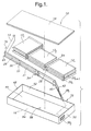
- FIG. 1 illustrates an improved battery pack 10 according to the invention.
- the pack 10 may be used for portable or stationary electrical and/or electronic devices, including commercial apparatus such as medical devices.
- the basic component of the battery pack 10 is a so-called bicell, as know in the art, for example, by reference to U.S. Patent No. 6,063,519 issued to Jeremy Barker, et al.
- a plurality of bicells are arranged, as will be seen, to form a battery unit, sometimes referred to as a soft-pack.
- a plurality of battery units are arranged together to from a battery modules which has terminals for delivering power. Finally, a plurality of battery modules are arranged to form the overall battery pack. Thus, the progression is as follows: bicell ⁇ battery unit ⁇ battery module ⁇ battery pack.
- Battery pack 10 may include a plurality of battery modules 12 1 , 12 2 , to 12 n , where n is an integer, a flexible circuit 14, and a case 16 with a top 18.
- the battery modules 12 n may be rechargeable lithium polymer (LiPo) battery modules configured to provide electrical power. Other chemistries, such as other lithium chemistries, may also be used.
- Each battery module 12 n may include a plurality of individual battery units 20 (as shown in Figures 3-4A-F), one or more positive terminals 22, and one or more negative terminals 24. Each terminal 22, 24 may have a respective tang 26.
- the flexible circuit 14 is configured to establish control and power connections between and among the individual battery modules 12 n , the case 16 and other electronics to be described below.
- flexible circuit 14 couples the battery modules 12 n in a series-connected arrangement, and allows electrical power to flow in (charge) and out (discharge) of case 16.
- flexible circuit 14 may include a substrate 28, a plurality of windows 30, a plurality of conductive traces 31, a plurality of flaps 32, and one or more jumpers 34.
- Flexible substrate 28 may be generally flexible, and may be of a material such as MYLAR® by E. I. Du Pont de Nemours and Company or the like.
- Substrate 28 is configured to contain a number of conductive traces 31 for establishing the above mentioned connections.
- Conductive traces 31 may run along the length of the substrate 28 and may be made of copper or another conductive material.
- Flexible circuit 14 may also include one or more windows 30 cut from substrate 28. Flaps 32 made of a conductive material, such as copper, fold out from windows 30, the conductive material being exposed once one side of the flexible substrate 28 is removed from the cut window 30 and the remaining substrate 28 and conductive material are folded to create window 30 and flap 32. Flaps 32 are electrically connected to conductive traces 31.
- Windows 30 may be oversized to allow for thermal expansion of flaps 32 when flaps 32 are electrically connected to terminals 22, 24.
- negative terminal 24 of each battery unit 20 is ultrasonically welded to corresponding flap 32 on flexible circuit 14 via tang 26.
- Flexible circuit 14 may also include one or more jumpers 34, which allow the connection of battery modules 12 n in a series-connected arrangement. It should be appreciated that jumpers 34 permit connections over conductive traces 31 without being electrically connected to traces 31 themselves.
- Flexible circuit 14 may also include a controller connector 36, a pack connector 38, a fuse 40, and a current sensor 42, all of which are elements known to those with ordinary skill in the art.
- Controller connector 36 provides electrical and mechanical termination of various power and control signals between a controller (best shown in Figure 2) dedicated to pack 10 and flexible circuit 14.
- Overall pack connector 38 comprises a pair of mating portions 38 1 and 38 2 , and provides power and control from inside battery pack 10 to the outside world.
- Fuse 40 and sensor 42 provide their conventional functions. Particularly, fuse 40 is configured to "open" electrically when a predetermined current (e.g ., a DC current) is being sourced by pack 10.
- Sensor 42 generates a current indicative signal representing the level of DC current being provided by pack 10.
- Flexible circuit 14 may also include a living hinge 44 which allows flexible circuit 14 to be oriented such that the location of selected windows 30 and flaps 32 can be configured to electrically connect to terminals 22, 24 of end module 12 n . There may be, however, no hinges or bends or several, depending on the particular design of the case.
- Figure 1 also shows a case 16 and top 18 which cooperate to enclose and protect the interior components of battery pack 10, namely modules 12 and flexible circuit 14.
- the case 16 includes a bottom 46, two end walls 48, 50 and two side walls 52, 54 which form an interior 56. Interior 56 houses, in effect, modules 12 and flexible circuit 14.
- Case 16 and top 18 may comprise electrical insulating material, for example a polyester or a plastic.
- FIG. 2 shows, in schematic and block diagram form, battery pack 10 in greater detail as employed in a preferred environment, specifically further including a battery controller 58, package connector 38 comprising a positive polarity (+) terminal 60 and a negative polarity (-) terminal 62, communication terminals such as a transmit (Tx) terminal 64 and a receive (Rx) terminal 66, and a control terminal such as a charge circuit line 68.
- Figure 2 further shows a master controller 70, a charger 72, a power source 74, and an electrical load 76.
- pack 10 may be used to provide (discharge) power to a load 76 or to receive power (recharge) through a charger 72.
- Positive polarity terminal 60 is connected to charger 72, which is also connected to current sensor 42. Both charger 72 and current sensor 42 are connected to battery controller 58 through battery controller connector 36.
- Negative polarity terminal 62 is also connected to charger 72 and fuse 40.
- Transmit terminal 64 is connected to battery controller 58 through controller connector 36 and to master controller 70 through pack connector 38.
- Receive terminal 66 which is connected to battery controller 58 through controller connector 36 and is also connected to master controller 70 through pack connector 38.
- Charge circuit line 68 which is connected to battery controller 58 through controller connector 36, is also connected to master controller 70 through pack connector 38.
- master controller 70 When the battery pack is providing power to a load 76, master controller 70 allows the positive and negative polarity terminals 60, 62 to pass through charger 72 to power load 76. When battery pack 10 needs recharging, as determined by master controller 70, the terminal leads 60, 62 are reconfigured so as to be recharged by charger 72 connected to power source 74. Master controller 70 determines charge or recharge configuration dependent upon information supplied by battery controller 58. Voltage information is supplied to battery controller 58 via controller connector 36, which is connected to transmit terminal 64 and receive terminal 66.
- Transmit terminal 64 and receive terminal 66 send and obtain voltage information about individual battery units 20, individual battery modules 12, and the overall battery pack 10, information which has been collected via the electrical connection of terminals 22, 24 of battery units 20 (plurality of units 20 comprising battery modules 12) to flexible circuit 14 via flaps 32.
- battery units 20 are electrically connected in a series-connected arrangement (shown best by Figure 4).
- Each negative terminal 24 of the individual battery units 20 (which is electrically connected to positive terminal 22 of adjacent battery unit 20, connected in series) is electrically connected to flexible circuit 14 via flaps 32. This is accomplished by ultrasonically welding tang 26 of negative terminal 24 to corresponding flap 32 in flexible circuit 14. As previously discussed each flap 32 corresponds to electrically conductive trace 31 running through flexible circuit 14. Traces 31 connect to controller connector 36. Because each battery unit 20 n is connected to flexible circuit 14 and adjacent battery unit 20 n+1 , a voltage lead for each battery unit 20 n is produced, which allows the voltage level of each battery unit 20 n to be read individually by battery controller 58.
- the voltage level information may be transmitted and received, via transmit terminal 64 and receive terminal 66, respectively to overall controller 70. Therefore, both the overall battery pack 10 voltage as well as the voltages of the individual battery cells 20 may be monitored.
- Positive terminal 22 of the end battery unit 20 is connected to the flexible circuit 14 although positive terminal 22 does not include a tang 26 in this embodiment. This connection is accomplished by ultrasonically welding negative terminal 24 to positive terminal 22 and ultrasonically welding tang 26 of negative terminal 24 to corresponding flap 32 of flexible circuit 14.
- Battery controller 58 may be configured to request recharge of battery pack 10 or one or more individual battery units 20 via charge circuit line 68, dependent upon the voltage readings of the individual components and overall battery pack 10.
- Use of the flexible circuit 14 to electrically connect battery modules 12, allows acquisition of information about each battery unit 20, each battery module 12, and battery pack 10 while providing a reduced-weight arrangement for electrically connecting the individual battery units 20 and battery modules 12.
- Connecting battery modules 12 to each other via flexible circuit 14 allows flexibility of battery pack 10 in at least two ways.
- Terminals 22, 24 which connect modules 12 to flexible circuit 14 also provide a voltage lead for each individual battery unit 20.
- terminals 22, 24 enable voltage sensing of individual modules 12 and the overall battery pack 10.
- the flex circuit 14 can be configured to couple the plurality of battery modules in parallel, thereby increasing amperage capacity (ampacity).
- flexible circuit may be configured to couple the plurality of modules in series, thereby increasing output voltage.
- the flex circuit can be configured to allow one tier, two tiers, or more of battery modules. The foregoing can be accomplished via appropriate routing and interconnection of traces 31 and/or jumpers.
- modules 12 can be oriented easily in various heights, widths, and depths. Flaps 32 in flexible circuit 14 may be oriented to correspond with terminals 22, 24 for electrical connection.
- the first aspect of the invention shows a battery pack 10 that is simpler to assemble, that uses electrical connections to both connect battery modules 12 and battery units 20 and obtain voltage information about individual modules 12 and battery units 20, and that allows numerous orientations and sizes of the battery pack 10 because of the use of the flexible circuit 14.
- Figure 3 shows an individual battery unit 20 in greater detail, and in various phases of constructions.
- a plurality of units 20 make up a module 12.
- An exploded view is designated 20 START
- an intermediate phase of construction is designated 20 INT
- a finished phase of construction is designated 20 FINISH .
- Figure 3 shows a plurality of bicells 78, a packaging envelope 80, an axis 82, adhesive layer 83, a first side of the battery unit 84, a second opposing side of the battery unit 86, a cover strip 85, positive polarity exposed grids 88, and negative polarity exposed grids 90, a vent 92, and a direction of rotation 94 relative to axis 82.
- Bicells 78 may comprise conventional bicells known to those of ordinary skill in the art, for example as seen by reference to U.S. Patent 6,063,519, issued to Barker, et al., hereby incorporated by reference.
- bicells 78 of battery unit 20 are connected in a parallel electrical relationship.
- the exposed grids 88, 90 are current carriers.
- the cathodic grids 88 are ultrasonically welded together leaving just an overall top and bottom surface thereof exposed.
- the anodic grids 90 are ultrasonically welded together leaving just an overall top and bottom surface exposed.
- each individual battery unit 20 has a positive terminal 22 located at a first end 84 of the battery unit 20 and a negative terminal 24 located at a second end 86.
- the second end 86 is located on an opposing side of battery unit 20 from first end 84, relative to a horizontal axis 82.
- negative terminal 24 is ultrasonically welded to the remaining exposed top surface of anodic grids 90.
- the positive terminal 22 is ultrasonically welded to the remaining exposed bottom surface of cathodic grids 88.
- the cover strip 85 is made of the same material as the corresponding terminal (positive or negative) 22, 24 and grid (positive or negative) 88, 90 and is placed above the grids 88, 90 or below the grids 88, 90, depending upon whether the terminal 22, 24 is either welded on the top of the stack of grids 88, 90 or below the stack of grids 88, 90. That is, the cover strip is placing on the opposing side relative to the terminal. That way, an electrosonic welding horn has opposing, reaction surfaces to grip. The strips minimize damage to the relatively fragile grid portion during welding.
- Packaging envelope 80 may comprise a single sheet which is folded to enclose the bicells 78.
- Packaging envelope 80 may be a type of laminated, aluminized flexible material which contains four layers.
- the outside layer exposed to the environment is an electrical insulating material, for example, a polyester.
- the next underlying layer is metallic, for example, aluminum. This metallic layer reduces or eliminates the amount of moisture outside of the packaging envelope 80 to which the battery unit 20 is exposed ( i.e ., provides a bidirectional moisture barrier).
- the third layer is of the same material as the outside layer.
- the fourth layer, layer 83 comprises an adhesive such as a conventional sealing hot melt adhesive, for example ethylene acrylic acid (EAA).
- EAA ethylene acrylic acid
- Packaging envelope 80 contains a vent 92, which allows any gas due to overcharging or other conditions to escape.
- opposing terminals 22, 24 allow the individual battery units 20 to be bussed as battery modules 12 in a compact form.
- An individual battery unit 20 can be rotated around horizontal axis 82 in a clockwise direction 94 by 180 degrees and placed on top of another battery unit 20.
- FIGS 4A through 4F show one construction process for a preferred embodiment of the invention.
- a first battery unit 20 1 , and additional battery units 20, are configured the following way.
- Positive terminals 22 (e . g ., aluminum) and negative terminals 24 (copper) of battery units 20 are oriented such that negative terminal 24 is electrically connected to the top surface of ultrasonically welded anodic exposed grids 90 and positive terminal 22 is electrically connected to the bottom surface of the ultrasonically welded cathodic exposed grids 88.
- a second battery unit 20 2 is placed adjacent first battery unit 20 1 ( Figure 4A) such that positive terminal 22 on bottom surface of second battery unit 20 2 is electrically connected to negative terminal 24 on top surface of first battery unit 20 1 ( Figure 4B).
- Second battery unit 20 2 is rotated clockwise about 180 degrees 94 around horizontal axis 82 such that negative terminal 24 of second battery unit 20 2 is oriented above positive terminal 22 of first battery unit 20 1 (Figure 4C).
- a third battery unit 20 3 may be placed on second battery unit 20 2 such that positive terminal 22 on bottom surface of third battery unit 20 3 is electrically connected to negative terminal 24 on top surface of second battery unit 20 2 ( Figure 4D). No rotation 94 of third battery unit 20 3 is required.
- a fourth battery unit 20 4 may be oriented as second battery unit 20 2 such that positive terminal 22 on bottom surface of fourth battery unit 20 4 is electrically connected to negative terminal 24 on top surface of third battery unit 20 3 ( Figure 4E).
- Fourth battery unit 20 4 is rotated clockwise about 180 degrees 94 around horizontal axis 82 such that negative terminal 24 of fourth battery unit 20 4 is oriented above positive terminal 22 of third battery unit 20 3 and first battery unit 20 1 ( Figure 4F).
- This "stacking" of successive battery units 20 can be repeated for a plurality of battery units 20.
- positive terminal 22 does not generally include a tang 26.
- the bottom terminal designated T BOTTOM may include a tang electrically connected thereto so as to facilitate connection to flexible circuit 14.
- the overall positive terminal of module 12 in T BOTTOM while the overall negative terminal of module 12 is designated T TOP .
- Each node it should be appreciated, also includes at least one tang, owing to the presence of a negative terminal. This allows voltage sensing for each unit 20.
- Terminal 24 comprises an electrically conductive tab and may be formed of copper or aluminum material. Terminal 24 allows individual battery unit 20 to be electrically connected to another individual battery unit 20, the flexible connection 14, or another electrical connection.
- the terminal 24 has a first region 96, a second region 98 having apertures 99 a , a third region 100, a fourth region 102, a first locating hole 104 and a second locating hole 106.
- terminal 24 has a tang 26 protruding from one edge of third region 100 along a lengthwise axis 101.
- the first region 96 may be welded to the exposed grids 90 of the plurality of bicells 78.
- apertures 99 a in region 98 a are arranged in a repeating pattern and comprise a standard slot, I-shape through aperture. This allows adhesive to flow therethrough.
- Figure 6 shows a second embodiment of second region, designated 98 b .
- the second region 98 b contains apertures 99 b cut through terminal 24.
- apertures 99 b run substantially the length of terminal 24.
- Packaging envelope 80 seals to itself through the apertures of second region 98 b at the sides 84, 86 because of the hot melt adhesive flows from above and below the apertures 98 b to adhere to itself.
- the apertures 98 b reduce or eliminate leaks of electrolyte solution from bicells 78 in at least two ways. First, the apertures 98 b allow packaging envelope 80 to more effectively seal because the hot melt adhesive binds with itself. Second, the design of the apertures 98 b creates a convoluted path by which the electrolyte solution must travel in order to leak from bicell 78.
- Figure 7 shows an enlarged view of a repeating pattern of apertures 98 b referred to in the encircled region designated "7" in Figure 6.
- Figure 7 shows a first axis 108, a transverse axis 110, L-shaped apertures 112, and I-shaped apertures 114.
- I-shaped apertures 114 are cut along a horizontal axis 108.
- I-shaped apertures 114 are located between sets of L-shaped apertures 112, wherein the long leg of the L-shaped aperture is located along the direction of transverse axis 110.
- a first orientation 112 a is oriented as the letter "L" in the conventional manner.
- a second orientation 112 b is the mirror image of the first orientation 112 a , the image being reflected with respect to transverse axis 110. This second orientation resembles a backward letter "L”.
- a third orientation 112 c is the mirror image of 112 a , the image being reflected through horizontal axis 108.
- a fourth orientation 112 d is the mirror image of second orientation 112 b , the image being reflected through horizontal axis 108.
- a first pattern 113 is located above a second pattern 115.
- first pattern 113 may include one third orientation L-shaped aperture 112 c , followed by one fourth orientation L-shaped aperture 112 d . Between the long legs of two L-shaped apertures 112 c , 112 d is located one I-shaped aperture 114 aligned along the horizontal axis 108.
- second pattern 115 may include one first orientation L-shaped aperture 112 a , followed by a second orientation L-shaped aperture 112 b . Between the long legs of the two L-shaped apertures 112 a , 112 b is located one I-shaped aperture 114 aligned along the horizontal axis 108.
- Figure 8 is a section view taken substantially along lines 8-8 in Figure 6 and shows a first side 120 and a second side 122 of terminal 24 in second region 98. This better illustrates how the apertures 98 a allow the hot melt adhesive of the packaging 80 to seal with itself.
- FIG 9 is a section view taken substantially along lines 9-9 in Figure 5 and shows an electrical insulator 124 applied to the fourth region 102 of the terminal 24.
- Insulator 124 such as a polyester, may be applied in the form of a tape or may be applied at the time of manufacture of terminal 24. These methods are known to those of ordinary skill in the art. Insulator 124 is applied to first side 120 of terminal 24, second side 122 of terminal 24, and edge 126 of terminal 24. Placement of insulator 124 reduces or eliminates shorting of terminal 24 that could be created if terminal 24 comes in contact with the aluminum layer of packaging envelope 80.
- Terminal 24 may contain first locating hole 104 and second locating hole 106. These holes 104, 106 may aid in welding of terminal 24 to exposed grids 88, 90 of plurality of bicells 78 and manufacture of battery unit 20 by aiding in alignment of components for sealing.
- terminal 24 aids in the sealing of packaging envelope in at least two ways. Apertures 99 a , 99 b allow hot melt adhesive of packaging envelope 80 to seal to itself. Further, apertures 99 b create a convoluted path, making it more difficult for electrolytic solution to leak from packaging envelope 80. In one embodiment, terminal 24 may include a tang 26 that aids in connection of battery unit 20 to flexible circuit 14. Terminal 24 is another aspect of the invention.
Landscapes
- Chemical & Material Sciences (AREA)
- Chemical Kinetics & Catalysis (AREA)
- Electrochemistry (AREA)
- General Chemical & Material Sciences (AREA)
- Engineering & Computer Science (AREA)
- Manufacturing & Machinery (AREA)
- Connection Of Batteries Or Terminals (AREA)
- Battery Mounting, Suspending (AREA)
Applications Claiming Priority (2)
| Application Number | Priority Date | Filing Date | Title |
|---|---|---|---|
| US09/919,304 US6746797B2 (en) | 2001-07-31 | 2001-07-31 | Battery pack having flexible circuit connector |
| US919304 | 2001-07-31 |
Publications (3)
| Publication Number | Publication Date |
|---|---|
| EP1282177A2 true EP1282177A2 (de) | 2003-02-05 |
| EP1282177A3 EP1282177A3 (de) | 2006-07-05 |
| EP1282177B1 EP1282177B1 (de) | 2011-03-16 |
Family
ID=25441862
Family Applications (1)
| Application Number | Title | Priority Date | Filing Date |
|---|---|---|---|
| EP02077698A Expired - Lifetime EP1282177B1 (de) | 2001-07-31 | 2002-07-08 | Batteriepack mit Verbinder für eine flexible Schaltung |
Country Status (4)
| Country | Link |
|---|---|
| US (1) | US6746797B2 (de) |
| EP (1) | EP1282177B1 (de) |
| AT (1) | ATE502406T1 (de) |
| DE (1) | DE60239437D1 (de) |
Cited By (3)
| Publication number | Priority date | Publication date | Assignee | Title |
|---|---|---|---|---|
| WO2007006169A1 (fr) * | 2005-05-31 | 2007-01-18 | Hingka Chung | Batterie lithium-ion de grande capacité de type à conduction par connexion à fiche |
| DE102009035469A1 (de) | 2009-07-31 | 2011-02-03 | Daimler Ag | Batterie mit einer Zellüberwachungsvorrichtung |
| GB2482324A (en) * | 2010-07-30 | 2012-02-01 | Energy Control Ltd | Battery assembly formed by plural soft packing secondary batteries. |
Families Citing this family (111)
| Publication number | Priority date | Publication date | Assignee | Title |
|---|---|---|---|---|
| JP3937839B2 (ja) * | 2001-12-28 | 2007-06-27 | 日本電気株式会社 | モジュール |
| JP2004071265A (ja) * | 2002-08-05 | 2004-03-04 | Sanyo Electric Co Ltd | 電池 |
| BRPI0519442B8 (pt) * | 2004-12-24 | 2023-01-10 | Lg Chemical Ltd | Conjunto de placas sensoras montado em um módulo de bateria e módulo de bateria incluindo o referido conjunto |
| US7807290B2 (en) * | 2006-12-01 | 2010-10-05 | Zero Motorcycles Inc. | Battery cell assembly |
| US8039144B2 (en) * | 2007-07-12 | 2011-10-18 | Motorola Mobility, Inc. | Electrochemical cell with singular coupling and method for making same |
| US20090061302A1 (en) * | 2007-09-04 | 2009-03-05 | Scott John S | Battery pack including an electric harness and method of manufacturing the same |
| US7697281B2 (en) | 2008-09-05 | 2010-04-13 | Apple Inc. | Handheld computing device |
| US7869206B2 (en) | 2008-09-05 | 2011-01-11 | Apple Inc. | Handheld computing device |
| US7762848B2 (en) * | 2008-10-23 | 2010-07-27 | Lg Chem, Ltd. | Interconnect device for battery cell assemblies |
| US8532777B2 (en) * | 2008-10-31 | 2013-09-10 | Medtronic, Inc. | Implantable cardioverter defibrillator capacitor assembly with flex circuit |
| US9203063B2 (en) * | 2010-05-07 | 2015-12-01 | Wilcox Industries Corp. | Battery box and mounting shoe interface |
| KR101136310B1 (ko) * | 2010-06-07 | 2012-04-19 | 에스비리모티브 주식회사 | 배터리 팩 |
| US8642205B2 (en) * | 2010-08-09 | 2014-02-04 | Motorola Mobility Llc | Electrochemical battery pack with reduced magnetic field emission and corresponding devices |
| US9602914B2 (en) | 2010-08-27 | 2017-03-21 | Apple Inc. | Porting audio using a connector in a small form factor electronic device |
| US8515113B2 (en) | 2010-08-19 | 2013-08-20 | Apple Inc. | Composite microphone boot to optimize sealing and mechanical properties |
| US8391010B2 (en) | 2010-08-19 | 2013-03-05 | Apple Inc. | Internal frame optimized for stiffness and heat transfer |
| US8634204B2 (en) | 2010-08-19 | 2014-01-21 | Apple Inc. | Compact folded configuration for integrated circuit packaging |
| US8477492B2 (en) | 2010-08-19 | 2013-07-02 | Apple Inc. | Formed PCB |
| US8427379B2 (en) | 2010-08-19 | 2013-04-23 | Apple Inc. | Modular material antenna assembly |
| US9178192B2 (en) | 2011-05-13 | 2015-11-03 | Lg Chem, Ltd. | Battery module and method for manufacturing the battery module |
| US9496544B2 (en) | 2011-07-28 | 2016-11-15 | Lg Chem. Ltd. | Battery modules having interconnect members with vibration dampening portions |
| US8974938B2 (en) | 2011-08-30 | 2015-03-10 | Lg Chem, Ltd. | Battery system and method for coupling a battery cell assembly to an electrically non-conductive base member |
| US8871376B2 (en) | 2011-08-31 | 2014-10-28 | Lg Chem, Ltd. | Interconnection assemblies and methods for forming the interconnection assemblies in a battery module |
| US9287627B2 (en) | 2011-08-31 | 2016-03-15 | Apple Inc. | Customizable antenna feed structure |
| US9406999B2 (en) | 2011-09-23 | 2016-08-02 | Apple Inc. | Methods for manufacturing customized antenna structures |
| US9324981B2 (en) * | 2012-01-20 | 2016-04-26 | GM Global Technology Operations LLC | Cell frame for extended range electric vehicle battery module |
| US8986872B2 (en) * | 2012-02-15 | 2015-03-24 | GM Global Technology Operations LLC | Battery design |
| US8846240B2 (en) | 2012-02-16 | 2014-09-30 | Lg Chem, Ltd. | Battery cell interconnect and voltage sensing assembly and method of manufacturing the assembly |
| US20140193680A1 (en) * | 2013-01-08 | 2014-07-10 | Samsung Sdi Co., Ltd. | Battery module |
| US9437859B2 (en) | 2014-04-07 | 2016-09-06 | Lg Chem, Ltd. | Battery cell interconnect and voltage sensing assembly and a battery module |
| US9620761B2 (en) | 2014-09-09 | 2017-04-11 | Lg Chem, Ltd. | Battery cell interconnect and voltage sensing assembly and a battery module |
| JP6505841B2 (ja) | 2014-12-01 | 2019-04-24 | カーディアック ペースメイカーズ, インコーポレイテッド | 埋め込み可能な医療装置 |
| ES2713231T3 (es) | 2015-02-06 | 2019-05-20 | Cardiac Pacemakers Inc | Sistemas para el suministro seguro de una terapia de estimulación eléctrica |
| US9905892B2 (en) | 2015-02-09 | 2018-02-27 | Lg Chem, Ltd. | Battery module and method of coupling first and second electrical terminals of first and second battery cells to first and second voltage sense members of an interconnect assembly |
| US10020483B2 (en) | 2015-02-09 | 2018-07-10 | Lg Chem, Ltd. | Battery module and method of coupling first and second electrical terminals of first and second battery cells to a voltage sense member of an interconnect assembly |
| WO2016130477A2 (en) | 2015-02-09 | 2016-08-18 | Cardiac Pacemakers, Inc. | Implantable medical device with radiopaque id tag |
| US11285326B2 (en) | 2015-03-04 | 2022-03-29 | Cardiac Pacemakers, Inc. | Systems and methods for treating cardiac arrhythmias |
| CN108136187B (zh) | 2015-08-20 | 2021-06-29 | 心脏起搏器股份公司 | 用于医疗装置之间的通信的系统和方法 |
| WO2017031221A1 (en) | 2015-08-20 | 2017-02-23 | Cardiac Pacemakers, Inc. | Systems and methods for communication between medical devices |
| US10226631B2 (en) | 2015-08-28 | 2019-03-12 | Cardiac Pacemakers, Inc. | Systems and methods for infarct detection |
| WO2017040115A1 (en) | 2015-08-28 | 2017-03-09 | Cardiac Pacemakers, Inc. | System for detecting tamponade |
| EP3341076B1 (de) | 2015-08-28 | 2022-05-11 | Cardiac Pacemakers, Inc. | Systeme und verfahren zur detektion von verhaltensreaktionssignalen und verabreichung einer therapie |
| WO2017062806A1 (en) | 2015-10-08 | 2017-04-13 | Cardiac Pacemakers, Inc. | Devices and methods for adjusting pacing rates in an implantable medical device |
| EP3389775B1 (de) | 2015-12-17 | 2019-09-25 | Cardiac Pacemakers, Inc. | Geführte kommunikation in einem medizinischen vorrichtungssystem |
| US10905886B2 (en) | 2015-12-28 | 2021-02-02 | Cardiac Pacemakers, Inc. | Implantable medical device for deployment across the atrioventricular septum |
| WO2017127548A1 (en) | 2016-01-19 | 2017-07-27 | Cardiac Pacemakers, Inc. | Devices for wirelessly recharging a rechargeable battery of an implantable medical device |
| EP3411113B1 (de) | 2016-02-04 | 2019-11-27 | Cardiac Pacemakers, Inc. | Einführungssystem mit kraftsensor für drahtlose kardiale vorrichtung |
| WO2017173275A1 (en) | 2016-03-31 | 2017-10-05 | Cardiac Pacemakers, Inc. | Implantable medical device with rechargeable battery |
| US10328272B2 (en) | 2016-05-10 | 2019-06-25 | Cardiac Pacemakers, Inc. | Retrievability for implantable medical devices |
| US10668294B2 (en) | 2016-05-10 | 2020-06-02 | Cardiac Pacemakers, Inc. | Leadless cardiac pacemaker configured for over the wire delivery |
| CN109414582B (zh) | 2016-06-27 | 2022-10-28 | 心脏起搏器股份公司 | 使用皮下感测p波进行再同步起搏管理的心脏治疗系统 |
| US11207527B2 (en) | 2016-07-06 | 2021-12-28 | Cardiac Pacemakers, Inc. | Method and system for determining an atrial contraction timing fiducial in a leadless cardiac pacemaker system |
| WO2018009392A1 (en) | 2016-07-07 | 2018-01-11 | Cardiac Pacemakers, Inc. | Leadless pacemaker using pressure measurements for pacing capture verification |
| EP3487579B1 (de) | 2016-07-20 | 2020-11-25 | Cardiac Pacemakers, Inc. | System zur verwendung eines vorhofkontraktionszeitmarkers bei einem elektrodenlosen herzschrittmachersystem |
| EP3500342B1 (de) | 2016-08-19 | 2020-05-13 | Cardiac Pacemakers, Inc. | Transseptale implantierbare medizinische vorrichtung |
| US10870008B2 (en) | 2016-08-24 | 2020-12-22 | Cardiac Pacemakers, Inc. | Cardiac resynchronization using fusion promotion for timing management |
| WO2018039335A1 (en) | 2016-08-24 | 2018-03-01 | Cardiac Pacemakers, Inc. | Integrated multi-device cardiac resynchronization therapy using p-wave to pace timing |
| WO2018057626A1 (en) | 2016-09-21 | 2018-03-29 | Cardiac Pacemakers, Inc. | Implantable cardiac monitor |
| WO2018057318A1 (en) | 2016-09-21 | 2018-03-29 | Cardiac Pacemakers, Inc. | Leadless stimulation device with a housing that houses internal components of the leadless stimulation device and functions as the battery case and a terminal of an internal battery |
| US10758737B2 (en) | 2016-09-21 | 2020-09-01 | Cardiac Pacemakers, Inc. | Using sensor data from an intracardially implanted medical device to influence operation of an extracardially implantable cardioverter |
| EP3532159B1 (de) | 2016-10-27 | 2021-12-22 | Cardiac Pacemakers, Inc. | System zur einführung einer implantierbaren medizinischen vorrichtung mit integriertem sensor |
| US10561330B2 (en) | 2016-10-27 | 2020-02-18 | Cardiac Pacemakers, Inc. | Implantable medical device having a sense channel with performance adjustment |
| EP3532161B1 (de) | 2016-10-27 | 2023-08-30 | Cardiac Pacemakers, Inc. | Implantierbare medizinische vorrichtung mit drucksensor |
| US10413733B2 (en) | 2016-10-27 | 2019-09-17 | Cardiac Pacemakers, Inc. | Implantable medical device with gyroscope |
| EP3532160B1 (de) | 2016-10-27 | 2023-01-25 | Cardiac Pacemakers, Inc. | Separate vorrichtung bei der verwaltung der schrittpulsenergie eines herzschrittmachers |
| US10463305B2 (en) | 2016-10-27 | 2019-11-05 | Cardiac Pacemakers, Inc. | Multi-device cardiac resynchronization therapy with timing enhancements |
| US10617874B2 (en) | 2016-10-31 | 2020-04-14 | Cardiac Pacemakers, Inc. | Systems and methods for activity level pacing |
| WO2018081721A1 (en) | 2016-10-31 | 2018-05-03 | Cardiac Pacemakers, Inc | Systems for activity level pacing |
| US10583301B2 (en) | 2016-11-08 | 2020-03-10 | Cardiac Pacemakers, Inc. | Implantable medical device for atrial deployment |
| EP3538213B1 (de) | 2016-11-09 | 2023-04-12 | Cardiac Pacemakers, Inc. | Systeme und vorrichtungen zur einstellung der herzschrittimpulsparameter für einen herzschrittmacher |
| US10639486B2 (en) | 2016-11-21 | 2020-05-05 | Cardiac Pacemakers, Inc. | Implantable medical device with recharge coil |
| US11147979B2 (en) | 2016-11-21 | 2021-10-19 | Cardiac Pacemakers, Inc. | Implantable medical device with a magnetically permeable housing and an inductive coil disposed about the housing |
| US10894163B2 (en) | 2016-11-21 | 2021-01-19 | Cardiac Pacemakers, Inc. | LCP based predictive timing for cardiac resynchronization |
| US10881869B2 (en) | 2016-11-21 | 2021-01-05 | Cardiac Pacemakers, Inc. | Wireless re-charge of an implantable medical device |
| EP3541473B1 (de) | 2016-11-21 | 2020-11-11 | Cardiac Pacemakers, Inc. | Elektrodenloser herzschrittmacher mit multimodaler kommunikation |
| US11207532B2 (en) | 2017-01-04 | 2021-12-28 | Cardiac Pacemakers, Inc. | Dynamic sensing updates using postural input in a multiple device cardiac rhythm management system |
| US10835753B2 (en) | 2017-01-26 | 2020-11-17 | Cardiac Pacemakers, Inc. | Intra-body device communication with redundant message transmission |
| WO2018140623A1 (en) | 2017-01-26 | 2018-08-02 | Cardiac Pacemakers, Inc. | Leadless device with overmolded components |
| WO2018140797A1 (en) | 2017-01-26 | 2018-08-02 | Cardiac Pacemakers, Inc. | Leadless implantable device with detachable fixation |
| AU2018248361B2 (en) | 2017-04-03 | 2020-08-27 | Cardiac Pacemakers, Inc. | Cardiac pacemaker with pacing pulse energy adjustment based on sensed heart rate |
| US10905872B2 (en) | 2017-04-03 | 2021-02-02 | Cardiac Pacemakers, Inc. | Implantable medical device with a movable electrode biased toward an extended position |
| WO2019036568A1 (en) | 2017-08-18 | 2019-02-21 | Cardiac Pacemakers, Inc. | IMPLANTABLE MEDICAL DEVICE COMPRISING A FLOW CONCENTRATOR AND A RECEPTION COIL PROVIDED AROUND THE FLOW CONCENTRATOR |
| WO2019036600A1 (en) | 2017-08-18 | 2019-02-21 | Cardiac Pacemakers, Inc. | IMPLANTABLE MEDICAL DEVICE WITH PRESSURE SENSOR |
| JP6938778B2 (ja) | 2017-09-20 | 2021-09-22 | カーディアック ペースメイカーズ, インコーポレイテッド | 複数の作動モードを備えた移植式医療用装置 |
| US11185703B2 (en) | 2017-11-07 | 2021-11-30 | Cardiac Pacemakers, Inc. | Leadless cardiac pacemaker for bundle of his pacing |
| CN111417433B (zh) | 2017-12-01 | 2024-04-30 | 心脏起搏器股份公司 | 从心室植入的无引线心脏起搏器检测心室充盈期间心房收缩定时基准的方法和系统 |
| CN111432874A (zh) | 2017-12-01 | 2020-07-17 | 心脏起搏器股份公司 | 从心室植入的无引线心脏起搏器检测搜索窗口内心房收缩定时基准的方法和系统 |
| EP3717063B1 (de) | 2017-12-01 | 2023-12-27 | Cardiac Pacemakers, Inc. | Systeme zum erkennen von vorhofkontraktions-timing-bezugswerte und zum bestimmen eines herzintervalls von einem ventrikulär implantierten leitungslosen herzschrittmacher |
| US11813463B2 (en) | 2017-12-01 | 2023-11-14 | Cardiac Pacemakers, Inc. | Leadless cardiac pacemaker with reversionary behavior |
| CN111556773A (zh) | 2018-01-04 | 2020-08-18 | 心脏起搏器股份公司 | 无逐搏通信的双腔起搏 |
| US11529523B2 (en) | 2018-01-04 | 2022-12-20 | Cardiac Pacemakers, Inc. | Handheld bridge device for providing a communication bridge between an implanted medical device and a smartphone |
| CN111886046B (zh) | 2018-03-23 | 2025-05-27 | 美敦力公司 | Av同步vfa心脏治疗 |
| JP2021518192A (ja) | 2018-03-23 | 2021-08-02 | メドトロニック,インコーポレイテッド | VfA心臓再同期治療 |
| CN111936046B (zh) | 2018-03-23 | 2024-06-28 | 美敦力公司 | 用于心动过速的vfa心脏治疗 |
| US11235161B2 (en) | 2018-09-26 | 2022-02-01 | Medtronic, Inc. | Capture in ventricle-from-atrium cardiac therapy |
| US11951313B2 (en) | 2018-11-17 | 2024-04-09 | Medtronic, Inc. | VFA delivery systems and methods |
| US12296177B2 (en) | 2018-12-21 | 2025-05-13 | Medtronic, Inc. | Delivery systems and methods for left ventricular pacing |
| US11679265B2 (en) | 2019-02-14 | 2023-06-20 | Medtronic, Inc. | Lead-in-lead systems and methods for cardiac therapy |
| US11697025B2 (en) | 2019-03-29 | 2023-07-11 | Medtronic, Inc. | Cardiac conduction system capture |
| US11213676B2 (en) | 2019-04-01 | 2022-01-04 | Medtronic, Inc. | Delivery systems for VfA cardiac therapy |
| US11712188B2 (en) | 2019-05-07 | 2023-08-01 | Medtronic, Inc. | Posterior left bundle branch engagement |
| US11305127B2 (en) | 2019-08-26 | 2022-04-19 | Medtronic Inc. | VfA delivery and implant region detection |
| JP7223280B2 (ja) * | 2019-09-13 | 2023-02-16 | トヨタ自動車株式会社 | 電池モジュール |
| EP3806273A1 (de) | 2019-10-11 | 2021-04-14 | Black & Decker Inc. | Elektrowerkzeug mit aufnahme von batteriepacks mit unterschiedlicher kapazität |
| US11813466B2 (en) | 2020-01-27 | 2023-11-14 | Medtronic, Inc. | Atrioventricular nodal stimulation |
| US12543992B2 (en) | 2020-03-30 | 2026-02-10 | Medtronic, Inc. | Pacing efficacy determination using a representative morphology of external cardiac signals |
| US11911168B2 (en) | 2020-04-03 | 2024-02-27 | Medtronic, Inc. | Cardiac conduction system therapy benefit determination |
| US12605103B2 (en) | 2020-05-21 | 2026-04-21 | Medtronic, Inc. | QRS detection and bracketing |
| US12465770B2 (en) | 2020-07-31 | 2025-11-11 | Medtronic, Inc. | Coronary sinus conduction system pacing and delivery |
| US11813464B2 (en) | 2020-07-31 | 2023-11-14 | Medtronic, Inc. | Cardiac conduction system evaluation |
| US20250381854A1 (en) * | 2024-06-17 | 2025-12-18 | Ford Global Technologies, Llc | Daisy-chain dc automotive power module connections |
Citations (5)
| Publication number | Priority date | Publication date | Assignee | Title |
|---|---|---|---|---|
| US5358798A (en) | 1993-12-06 | 1994-10-25 | Motorola, Inc. | Battery assembly having a thermal fuse |
| US5482793A (en) | 1993-10-04 | 1996-01-09 | Motorola, Inc. | Assembly having improved thermal sensing capability |
| US5639571A (en) | 1996-06-24 | 1997-06-17 | General Motors Corporation | Battery pack |
| US5796588A (en) | 1994-09-29 | 1998-08-18 | Sanyo Electric Co., Ltd. | Electrical apparatus containing batteries |
| US6063519A (en) | 1998-05-15 | 2000-05-16 | Valence Technology, Inc. | Grid placement in lithium ion bi-cell counter electrodes |
Family Cites Families (19)
| Publication number | Priority date | Publication date | Assignee | Title |
|---|---|---|---|---|
| US5619117A (en) | 1982-06-07 | 1997-04-08 | Norand Corporation | Battery pack having memory |
| US5224870A (en) | 1991-01-11 | 1993-07-06 | Physio-Control Corporation | Battery pack |
| US5202198A (en) | 1992-03-26 | 1993-04-13 | General Motors Corporation | Battery construction and method of connecting terminals to electrodes |
| US5588884A (en) | 1995-09-08 | 1996-12-31 | Packard Hughes Interconnect Company | Stamped and formed contacts for a power connector |
| US5895728A (en) | 1995-09-27 | 1999-04-20 | Bolder Technologies Corp. | Battery case |
| DE19607226A1 (de) | 1996-02-27 | 1997-09-04 | Metabowerke Kg | Akku-Ladegerät für Elektrohandwerkzeuge |
| JP2821420B2 (ja) | 1996-05-14 | 1998-11-05 | 静岡日本電気株式会社 | 小型電子機器の電池用端子とその保持構造 |
| US5805423A (en) | 1996-05-17 | 1998-09-08 | United Technologies Automotive | Battery contact and retention apparatus for printed circuit boards |
| US6040684A (en) | 1997-06-30 | 2000-03-21 | Compaq Computer Corporation | Lithium ion fast pulse charger |
| TW398087B (en) | 1997-07-22 | 2000-07-11 | Sanyo Electric Co | Pack cell |
| US6080508A (en) | 1998-03-06 | 2000-06-27 | Electrofuel Inc. | Packaging assembly for a lithium battery |
| US6183912B1 (en) | 1998-05-29 | 2001-02-06 | Delphi Technologies, Inc. | High energy glass containing carbon electrode for lithium battery |
| US5999410A (en) * | 1998-07-29 | 1999-12-07 | Centurion International, Inc. | Flexible circuit board configurable for use with different types of battery packs |
| US6165639A (en) | 1998-09-30 | 2000-12-26 | Motorola, Inc. | Method and apparatus for making internal connections within a battery pack |
| US6413668B1 (en) | 2000-01-10 | 2002-07-02 | Delphi Technologies, Inc. | Lithium ion battery and container |
| US6423441B1 (en) * | 2000-01-12 | 2002-07-23 | Delphi Technologies, Inc. | Battery pack signal routing system |
| US6406815B1 (en) | 2000-02-11 | 2002-06-18 | Delphi Technologies, Inc. | Compact lithium ion battery and method of manufacturing |
| US6419712B1 (en) | 2000-05-10 | 2002-07-16 | Delphi Technologies, Inc. | Lithium polymer consistent lamination process |
| US6617078B1 (en) | 2000-08-10 | 2003-09-09 | Delphi Technologies, Inc. | Lithium ion rechargeable batteries utilizing chlorinated polymer blends |
-
2001
- 2001-07-31 US US09/919,304 patent/US6746797B2/en not_active Expired - Fee Related
-
2002
- 2002-07-08 AT AT02077698T patent/ATE502406T1/de not_active IP Right Cessation
- 2002-07-08 EP EP02077698A patent/EP1282177B1/de not_active Expired - Lifetime
- 2002-07-08 DE DE60239437T patent/DE60239437D1/de not_active Expired - Lifetime
Patent Citations (5)
| Publication number | Priority date | Publication date | Assignee | Title |
|---|---|---|---|---|
| US5482793A (en) | 1993-10-04 | 1996-01-09 | Motorola, Inc. | Assembly having improved thermal sensing capability |
| US5358798A (en) | 1993-12-06 | 1994-10-25 | Motorola, Inc. | Battery assembly having a thermal fuse |
| US5796588A (en) | 1994-09-29 | 1998-08-18 | Sanyo Electric Co., Ltd. | Electrical apparatus containing batteries |
| US5639571A (en) | 1996-06-24 | 1997-06-17 | General Motors Corporation | Battery pack |
| US6063519A (en) | 1998-05-15 | 2000-05-16 | Valence Technology, Inc. | Grid placement in lithium ion bi-cell counter electrodes |
Cited By (4)
| Publication number | Priority date | Publication date | Assignee | Title |
|---|---|---|---|---|
| WO2007006169A1 (fr) * | 2005-05-31 | 2007-01-18 | Hingka Chung | Batterie lithium-ion de grande capacité de type à conduction par connexion à fiche |
| DE102009035469A1 (de) | 2009-07-31 | 2011-02-03 | Daimler Ag | Batterie mit einer Zellüberwachungsvorrichtung |
| GB2482324A (en) * | 2010-07-30 | 2012-02-01 | Energy Control Ltd | Battery assembly formed by plural soft packing secondary batteries. |
| GB2482324B (en) * | 2010-07-30 | 2018-02-14 | Energy Control Ltd | Battery assembly formed by plural soft packing secondary batteies |
Also Published As
| Publication number | Publication date |
|---|---|
| EP1282177A3 (de) | 2006-07-05 |
| DE60239437D1 (de) | 2011-04-28 |
| EP1282177B1 (de) | 2011-03-16 |
| ATE502406T1 (de) | 2011-04-15 |
| US6746797B2 (en) | 2004-06-08 |
| US20030027039A1 (en) | 2003-02-06 |
Similar Documents
| Publication | Publication Date | Title |
|---|---|---|
| US6746797B2 (en) | Battery pack having flexible circuit connector | |
| US6811902B2 (en) | Battery pack having improved battery cell terminal configuration | |
| US6729908B2 (en) | Battery pack having perforated terminal arrangement | |
| US11431063B2 (en) | Battery module having structure facilitating series-parallel connections and battery pack comprising same | |
| US10720626B2 (en) | Systems and methods for battery structure, interconnects, sensing, and balancing | |
| JP6472544B2 (ja) | 電極リード連結構造物、電極リード連結構造物を含む電池モジュール及びこれを含む電池パック | |
| EP2077595A2 (de) | Schutzleiterplatte, Batteriepack und zugehörige Verfahren | |
| TW201521271A (zh) | 新穎鋰離子電池 | |
| KR20170025384A (ko) | 배터리 팩 | |
| US20160164051A1 (en) | Secondary battery and battery pack including the same | |
| WO2018230805A1 (ko) | 배터리 팩 | |
| US10629885B2 (en) | Electric storage device | |
| EP1218956B1 (de) | Batteriedose | |
| JP7428331B2 (ja) | パウチセルの内圧測定用の軟性印刷回路基板及びパウチセルの内圧測定方法 | |
| KR102543155B1 (ko) | 버스바 프레임 및 이를 갖는 배터리 모듈 | |
| CN116075975B (zh) | 包括用于连接器的有效布局的汇流条框架的电池模块及包括该电池模块的电池组 | |
| KR102134120B1 (ko) | 저 프로파일 센서 및 이를 포함하는 전기화학 전지 | |
| CN215600459U (zh) | 绝缘膜、电池单体、电池及用电设备 | |
| CN114175334B (zh) | 二次电池 | |
| CN111313119B (zh) | 电池模块以及将单元监控电路载体组装到电池模块的方法 | |
| EP3671941B1 (de) | Sekundärbatterie und batteriepack diese enthaltend | |
| EP3671942B1 (de) | Anschlussgehäuse mit verbesserter funktion zur abschätzung des zustandes einer sekundärbatterie | |
| US20150380710A1 (en) | Battery holding devices and battery packages | |
| KR102526844B1 (ko) | 버스바 프레임 및 이를 갖는 배터리 모듈 | |
| KR20200064751A (ko) | 셀 성능 측정방법 |
Legal Events
| Date | Code | Title | Description |
|---|---|---|---|
| PUAI | Public reference made under article 153(3) epc to a published international application that has entered the european phase |
Free format text: ORIGINAL CODE: 0009012 |
|
| AK | Designated contracting states |
Designated state(s): AT BE BG CH CY CZ DE DK EE ES FI FR GB GR IE IT LI LU MC NL PT SE SK TR |
|
| AX | Request for extension of the european patent |
Extension state: AL LT LV MK RO SI |
|
| RAP1 | Party data changed (applicant data changed or rights of an application transferred) |
Owner name: ENERDEL, INC. |
|
| PUAL | Search report despatched |
Free format text: ORIGINAL CODE: 0009013 |
|
| AK | Designated contracting states |
Kind code of ref document: A3 Designated state(s): AT BE BG CH CY CZ DE DK EE ES FI FR GB GR IE IT LI LU MC NL PT SE SK TR |
|
| AX | Request for extension of the european patent |
Extension state: AL LT LV MK RO SI |
|
| RIC1 | Information provided on ipc code assigned before grant |
Ipc: H01M 2/30 20060101ALI20060526BHEP Ipc: H01M 2/02 20060101AFI20021218BHEP Ipc: H01M 10/48 20060101ALI20060526BHEP |
|
| 17P | Request for examination filed |
Effective date: 20061229 |
|
| AKX | Designation fees paid |
Designated state(s): AT BE BG CH CY CZ DE DK EE ES FI FR GB GR IE IT LI LU MC NL PT SE SK TR |
|
| 17Q | First examination report despatched |
Effective date: 20071011 |
|
| GRAP | Despatch of communication of intention to grant a patent |
Free format text: ORIGINAL CODE: EPIDOSNIGR1 |
|
| GRAS | Grant fee paid |
Free format text: ORIGINAL CODE: EPIDOSNIGR3 |
|
| RAP1 | Party data changed (applicant data changed or rights of an application transferred) |
Owner name: ENERDEL, INC. |
|
| GRAA | (expected) grant |
Free format text: ORIGINAL CODE: 0009210 |
|
| AK | Designated contracting states |
Kind code of ref document: B1 Designated state(s): AT BE BG CH CY CZ DE DK EE ES FI FR GB GR IE IT LI LU MC NL PT SE SK TR |
|
| REG | Reference to a national code |
Ref country code: GB Ref legal event code: FG4D |
|
| REG | Reference to a national code |
Ref country code: CH Ref legal event code: EP |
|
| REG | Reference to a national code |
Ref country code: IE Ref legal event code: FG4D |
|
| REF | Corresponds to: |
Ref document number: 60239437 Country of ref document: DE Date of ref document: 20110428 Kind code of ref document: P |
|
| REG | Reference to a national code |
Ref country code: DE Ref legal event code: R096 Ref document number: 60239437 Country of ref document: DE Effective date: 20110428 |
|
| REG | Reference to a national code |
Ref country code: NL Ref legal event code: VDEP Effective date: 20110316 |
|
| PG25 | Lapsed in a contracting state [announced via postgrant information from national office to epo] |
Ref country code: GR Free format text: LAPSE BECAUSE OF FAILURE TO SUBMIT A TRANSLATION OF THE DESCRIPTION OR TO PAY THE FEE WITHIN THE PRESCRIBED TIME-LIMIT Effective date: 20110617 Ref country code: ES Free format text: LAPSE BECAUSE OF FAILURE TO SUBMIT A TRANSLATION OF THE DESCRIPTION OR TO PAY THE FEE WITHIN THE PRESCRIBED TIME-LIMIT Effective date: 20110627 Ref country code: SE Free format text: LAPSE BECAUSE OF FAILURE TO SUBMIT A TRANSLATION OF THE DESCRIPTION OR TO PAY THE FEE WITHIN THE PRESCRIBED TIME-LIMIT Effective date: 20110316 |
|
| PG25 | Lapsed in a contracting state [announced via postgrant information from national office to epo] |
Ref country code: AT Free format text: LAPSE BECAUSE OF FAILURE TO SUBMIT A TRANSLATION OF THE DESCRIPTION OR TO PAY THE FEE WITHIN THE PRESCRIBED TIME-LIMIT Effective date: 20110316 Ref country code: BG Free format text: LAPSE BECAUSE OF FAILURE TO SUBMIT A TRANSLATION OF THE DESCRIPTION OR TO PAY THE FEE WITHIN THE PRESCRIBED TIME-LIMIT Effective date: 20110616 Ref country code: FI Free format text: LAPSE BECAUSE OF FAILURE TO SUBMIT A TRANSLATION OF THE DESCRIPTION OR TO PAY THE FEE WITHIN THE PRESCRIBED TIME-LIMIT Effective date: 20110316 Ref country code: CY Free format text: LAPSE BECAUSE OF FAILURE TO SUBMIT A TRANSLATION OF THE DESCRIPTION OR TO PAY THE FEE WITHIN THE PRESCRIBED TIME-LIMIT Effective date: 20110316 |
|
| PG25 | Lapsed in a contracting state [announced via postgrant information from national office to epo] |
Ref country code: BE Free format text: LAPSE BECAUSE OF FAILURE TO SUBMIT A TRANSLATION OF THE DESCRIPTION OR TO PAY THE FEE WITHIN THE PRESCRIBED TIME-LIMIT Effective date: 20110316 |
|
| PG25 | Lapsed in a contracting state [announced via postgrant information from national office to epo] |
Ref country code: EE Free format text: LAPSE BECAUSE OF FAILURE TO SUBMIT A TRANSLATION OF THE DESCRIPTION OR TO PAY THE FEE WITHIN THE PRESCRIBED TIME-LIMIT Effective date: 20110316 Ref country code: PT Free format text: LAPSE BECAUSE OF FAILURE TO SUBMIT A TRANSLATION OF THE DESCRIPTION OR TO PAY THE FEE WITHIN THE PRESCRIBED TIME-LIMIT Effective date: 20110718 |
|
| PGFP | Annual fee paid to national office [announced via postgrant information from national office to epo] |
Ref country code: FR Payment date: 20110727 Year of fee payment: 10 |
|
| PG25 | Lapsed in a contracting state [announced via postgrant information from national office to epo] |
Ref country code: SK Free format text: LAPSE BECAUSE OF FAILURE TO SUBMIT A TRANSLATION OF THE DESCRIPTION OR TO PAY THE FEE WITHIN THE PRESCRIBED TIME-LIMIT Effective date: 20110316 Ref country code: CZ Free format text: LAPSE BECAUSE OF FAILURE TO SUBMIT A TRANSLATION OF THE DESCRIPTION OR TO PAY THE FEE WITHIN THE PRESCRIBED TIME-LIMIT Effective date: 20110316 |
|
| PG25 | Lapsed in a contracting state [announced via postgrant information from national office to epo] |
Ref country code: NL Free format text: LAPSE BECAUSE OF FAILURE TO SUBMIT A TRANSLATION OF THE DESCRIPTION OR TO PAY THE FEE WITHIN THE PRESCRIBED TIME-LIMIT Effective date: 20110316 |
|
| PLBE | No opposition filed within time limit |
Free format text: ORIGINAL CODE: 0009261 |
|
| STAA | Information on the status of an ep patent application or granted ep patent |
Free format text: STATUS: NO OPPOSITION FILED WITHIN TIME LIMIT |
|
| 26N | No opposition filed |
Effective date: 20111219 |
|
| PG25 | Lapsed in a contracting state [announced via postgrant information from national office to epo] |
Ref country code: MC Free format text: LAPSE BECAUSE OF NON-PAYMENT OF DUE FEES Effective date: 20110731 Ref country code: DK Free format text: LAPSE BECAUSE OF FAILURE TO SUBMIT A TRANSLATION OF THE DESCRIPTION OR TO PAY THE FEE WITHIN THE PRESCRIBED TIME-LIMIT Effective date: 20110316 |
|
| REG | Reference to a national code |
Ref country code: CH Ref legal event code: PL |
|
| GBPC | Gb: european patent ceased through non-payment of renewal fee |
Effective date: 20110708 |
|
| REG | Reference to a national code |
Ref country code: DE Ref legal event code: R097 Ref document number: 60239437 Country of ref document: DE Effective date: 20111219 |
|
| REG | Reference to a national code |
Ref country code: IE Ref legal event code: MM4A |
|
| PG25 | Lapsed in a contracting state [announced via postgrant information from national office to epo] |
Ref country code: CH Free format text: LAPSE BECAUSE OF NON-PAYMENT OF DUE FEES Effective date: 20110731 Ref country code: LI Free format text: LAPSE BECAUSE OF NON-PAYMENT OF DUE FEES Effective date: 20110731 |
|
| PG25 | Lapsed in a contracting state [announced via postgrant information from national office to epo] |
Ref country code: IT Free format text: LAPSE BECAUSE OF FAILURE TO SUBMIT A TRANSLATION OF THE DESCRIPTION OR TO PAY THE FEE WITHIN THE PRESCRIBED TIME-LIMIT Effective date: 20110316 |
|
| PG25 | Lapsed in a contracting state [announced via postgrant information from national office to epo] |
Ref country code: GB Free format text: LAPSE BECAUSE OF NON-PAYMENT OF DUE FEES Effective date: 20110708 |
|
| PG25 | Lapsed in a contracting state [announced via postgrant information from national office to epo] |
Ref country code: IE Free format text: LAPSE BECAUSE OF NON-PAYMENT OF DUE FEES Effective date: 20110708 |
|
| REG | Reference to a national code |
Ref country code: FR Ref legal event code: ST Effective date: 20130329 |
|
| PG25 | Lapsed in a contracting state [announced via postgrant information from national office to epo] |
Ref country code: FR Free format text: LAPSE BECAUSE OF NON-PAYMENT OF DUE FEES Effective date: 20120731 |
|
| PG25 | Lapsed in a contracting state [announced via postgrant information from national office to epo] |
Ref country code: LU Free format text: LAPSE BECAUSE OF NON-PAYMENT OF DUE FEES Effective date: 20110708 |
|
| PG25 | Lapsed in a contracting state [announced via postgrant information from national office to epo] |
Ref country code: TR Free format text: LAPSE BECAUSE OF FAILURE TO SUBMIT A TRANSLATION OF THE DESCRIPTION OR TO PAY THE FEE WITHIN THE PRESCRIBED TIME-LIMIT Effective date: 20110316 |
|
| PGFP | Annual fee paid to national office [announced via postgrant information from national office to epo] |
Ref country code: DE Payment date: 20130703 Year of fee payment: 12 |
|
| REG | Reference to a national code |
Ref country code: DE Ref legal event code: R119 Ref document number: 60239437 Country of ref document: DE |
|
| PG25 | Lapsed in a contracting state [announced via postgrant information from national office to epo] |
Ref country code: DE Free format text: LAPSE BECAUSE OF NON-PAYMENT OF DUE FEES Effective date: 20150203 |
|
| REG | Reference to a national code |
Ref country code: DE Ref legal event code: R119 Ref document number: 60239437 Country of ref document: DE Effective date: 20150203 |