EP1282216A2 - Procédé de bobinage de l'armature d'une machine électrique à champ tournant - Google Patents
Procédé de bobinage de l'armature d'une machine électrique à champ tournant Download PDFInfo
- Publication number
- EP1282216A2 EP1282216A2 EP02017304A EP02017304A EP1282216A2 EP 1282216 A2 EP1282216 A2 EP 1282216A2 EP 02017304 A EP02017304 A EP 02017304A EP 02017304 A EP02017304 A EP 02017304A EP 1282216 A2 EP1282216 A2 EP 1282216A2
- Authority
- EP
- European Patent Office
- Prior art keywords
- winding
- needle
- coils
- rotating electrical
- electrical machine
- Prior art date
- Legal status (The legal status is an assumption and is not a legal conclusion. Google has not performed a legal analysis and makes no representation as to the accuracy of the status listed.)
- Withdrawn
Links
- 238000004804 winding Methods 0.000 title claims abstract description 148
- 238000000034 method Methods 0.000 title claims abstract description 51
- 239000000696 magnetic material Substances 0.000 claims description 6
- 239000011810 insulating material Substances 0.000 claims 1
- 239000012212 insulator Substances 0.000 description 16
- 238000010276 construction Methods 0.000 description 10
- 230000009471 action Effects 0.000 description 6
- 238000006073 displacement reaction Methods 0.000 description 3
- 238000009413 insulation Methods 0.000 description 2
- 238000003475 lamination Methods 0.000 description 2
- 230000002093 peripheral effect Effects 0.000 description 2
- 230000000712 assembly Effects 0.000 description 1
- 238000000429 assembly Methods 0.000 description 1
- 230000008859 change Effects 0.000 description 1
- 230000007423 decrease Effects 0.000 description 1
- 230000001939 inductive effect Effects 0.000 description 1
- 238000004519 manufacturing process Methods 0.000 description 1
- 230000004048 modification Effects 0.000 description 1
- 238000012986 modification Methods 0.000 description 1
- 230000008569 process Effects 0.000 description 1
- 230000002250 progressing effect Effects 0.000 description 1
- 238000004904 shortening Methods 0.000 description 1
Images



Classifications
-
- H—ELECTRICITY
- H02—GENERATION; CONVERSION OR DISTRIBUTION OF ELECTRIC POWER
- H02K—DYNAMO-ELECTRIC MACHINES
- H02K15/00—Processes or apparatus specially adapted for manufacturing, assembling, maintaining or repairing of dynamo-electric machines
- H02K15/08—Forming windings by laying conductors into or around core parts
- H02K15/095—Forming windings by laying conductors into or around core parts by laying conductors around salient poles
Definitions
- This invention relates to a method of winding armatures for revolving-field electrical machines and more particularly to an improved winding method that permits a greater coil density to be obtained and avoids the likelihood of damaging the wire by the winding needle during the winding operation and also to an improved armature construction.
- a first feature of this invention is adapted to be embodied in a method of winding the coils of a rotating electrical machine.
- a circular core of magnetic material with a plurality of magnetic pole teeth extending radially from the circular core is provided.
- Each of the magnetic pole teeth defines a core and slots formed therebetween.
- Each of the slots defines a mouth that is formed between adjacent outer ends of the cores.
- the winding method comprises the steps of positioning a threading needle having an opening through which the wire for the winding of the coils is fed into proximity to one of the mouths.
- the needle opening is moved in a path around one of the pole teeth without moving the needle in any substantial distance into the slot to form a first winding.
- the needle is moved in a generally circular path of greater length than the final length of the coil winding to provide slack in the length of the wire.
- Another feature of the invention is also adapted to be embodied in a method of winding the coils of a rotating electrical machine.
- a circular core of magnetic material with a plurality of magnetic pole teeth extending radially from the circular core is also provided.
- Each of the magnetic pole teeth defines a core and slots formed therebetween.
- This winding method comprises the steps of positioning a threading needle having an opening through which the wire for the winding of the coils is fed into proximity to each of the pole teeth and moving the needle in a path around the pole teeth to establish at least a first winding layer around the pole tooth. Then a thin insulating layer is positioned over the at least first winding layer and a further winding layer is placed over the insulating layer.
- a further feature of the invention is also adapted to be the coil windings for the armature of a rotating electrical machine.
- the armature comprises a circular core of magnetic material with a plurality of magnetic pole teeth extending radially from the circular core. Several layers of coil windings are formed on each of the magnetic pole teeth. At least one thin insulating layer is positioned between adjacent of the coil windings.
- FIG. 1 is a cross sectional view taken through a rotating electrical machine formed in accordance with one embodiment of the invention.
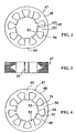
- FIG. 2 is an end elevational view of the laminations of the magnetic core looking from one side.
- FIG. 3 is a side elevational view of the core.
- FIG. 4 is end elevational view of the core looking in the opposite direction from FIG. 2.
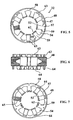
- FIG. 5 is an end elevational view, in part similar to FIG. 2, but shows the construction with the insulator in place with one portion of the insulator shaded to show how the side of the insulator is configured to assist in the winding operation.
- FIG. 6 is a side elevational view, in part similar to FIG. 3, but shows the core assembly with the insulator in place.
- FIG. 7 is an end elevational view, in part similar to FIG. 4 looking in the opposite direction from FIG. 5 and showing one portion of the insulator shaded to show how the side of the insulator is tapered.
- FIG. 8 is a cross sectional view of one of the poll teeth of this embodiment with the coil winding removed.
- FIG. 9 is a partial end elevational view taken in the direction of the arrow 9 in FIG. 8.
- FIG. 10 is a cross sectional view of the upper bobbin half taken along the same plane as FIG 8.
- FIG. 11 is an end elevational view looking in same direction as FIG. 9.
- FIGS. 12a - 12k are a series of cross sectional views taken at equal intervals along the length of FIG. 8 starting at the base of the pole tooth (left hand side) and ending at the tip (right hand side) thereof.
- FIG. 13 is a graphical view showing how the configuration of the circumference changing member affects the winding circumference.
- FIG. 14 is a view, in part similar to FIG. 5, and shows how the winding needle is associated with the slots between the pole teeth during the winding operation.
- FIG. 15 is a projected side elevational view showing the path the needle takes when winding one of the coil.
- FIG. 16 is a side view looking in a direction perpendicular to FIG. 15 and showing the same paths of travel of the winding needle.
- FIG. 17 is a partial side elevational view showing the path of the winding needle and how the slack is induced by moving the needle in a direction parallel to the axis of rotation of the machine.
- FIG. 18 is a side elevational view of the structure shown in FIG. 17, showing the slack inducing movement of the needle.
- FIG. 19 is a partial side elevational view, in part similar to FIG. 17, showing how the slack is introduced by moving the winding needle in another direction.
- FIG. 20 is a top plan view, in part similar to FIG. 18, but shows the needle displacement in the axial and radial directions.
- FIG. 21 is an exploded view showing a winding assist insert in accordance with an embodiment of the invention.
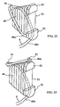
- FIG. 22 is a partially schematic perspective view showing another winding method for assisting in slack introduction.
- FIG. 23 is a view, in part similar to FIG. 22, and shows yet another winding method assist in accordance with the invention.
- a rotating electric machine constructed in accordance with the invention is identified generally by the reference 31.
- the rotating electric machine 31 may be either an electric motor or a generator depending upon the desired application.
- the rotating electrical machine 31 is comprised of a stator assembly, indicated generally by the reference numeral 32, and a rotor assembly, indicated generally by the reference numeral 33. These components are contained within a housing assembly that is comprised of a cup shaped, main housing piece 34 and a cover plate 35, which is suitably attached thereto to form an enclosure 36 in which the stator assembly 32 and rotor assembly 33 are positioned.
- the rotor assembly 33 is formed with a central portion 37 on which a plurality of circumferentially spaced permanent magnets 38 having alternating polarity are affixed in a known manner.
- the end portions of the rotor assembly 33 comprise shaft portions 39 and 41 that are journalled, respectively, in bearings 42 carried by an integral closure wall 43 of the cup shaped, main housing piece 34 and bearings 44 carried in a recessed portion 45 of the cover plate 35.
- the construction of the rotor assembly 33 may be deemed to be of the general conventional type and any type known in this art might be employed. Also, although the described machine employs an arrangement wherein a coil winding assembly, indicated generally by the reference numeral 46 is provided on individual armature poles, to be described, formed on the stator assembly 32, it should be understood that the coil winding assembly 46 can be mounted on the rotor assembly 33 and the permanent magnets 38 may be mounted as part of the stator assembly including the cup shaped, main housing piece 34.
- the stator assembly 32 is comprised of an armature core, indicated generally by the reference numeral 47, which is made up of a plurality of laminated armature plates as shown in FIGS. 2 through 4.
- the armature core 47 is the outer element of the rotating electric machine 31, it is comprised of a circular core portion 48 from which a plurality of pole teeth, each indicated generally by the reference numeral 49, extend.
- the pole teeth 49 have generally rectangular portions 51 that extend outwardly from the circular core portion 48 and which terminate in enlarged, projecting ends 52. Gaps 53 are formed between adjacent ends of these projecting ends 52, which form the outer termination of slots 54, formed between adjacent pole teeth 49.
- each of them is formed with a reference slot 55 on the outer periphery of their circular portion 48. This slot 55 assists in alignment as well as location within the cup shaped, main housing piece 34.
- the ends of the slots 54 adjacent the circular portion 48 of the armature core 47 is defined by angularly disposed surfaces 56 formed on opposite sides of the bases of each of the pole teeth 49. These act as projections that cooperate with the projecting ends 52 at the outer ends of the teeth 49 so as to assist in locate an insulating bobbin forming members 57 around which the coil winding assembly 46 is formed as well as locating the individual windings themselves.
- the insulating bobbin forming members 57 are comprised of right and left hand sections 57a and 57b, which have a substantially identical construction, except as will be hereinafter described.
- the insulating bobbin forming member 57 is comprised of a circular portion 58 that has an L-shaped cross section and from which extend individual legs 59 of a generally U-shape which is complimentary to and snuggly received on the core pole teeth 49.
- Inclined surfaces 60 at the base of these legs 59 cooperate with the aforenoted angularly disposed surfaces 56 formed at the outer ends of the pole teeth 49 so as to provide a stop or abutment against which the coil windings actually engage. This construction also facilitates alignment.
- the outer periphery of the circular portion 58 of the insulating bobbin forming member 57 extends to a lesser circumferential extent than the outer periphery of the circular portion 48 of the armature core 47.
- Projections, indicated at 63, are formed at circumferentially spaced locations around the periphery of the insulating bobbin forming member 57, at least one of which is aligned with the insulator leg portion 59 and another of which is positioned adjacent the intersection between the inclined surfaces 60 as best shown in FIG. 5.
- This construction is formed at one side of the insulator on one of the insulating bobbin forming member 57a or 57b. The spacing of these projections is chosen in order to facilitate the passage of wires connecting the individual coils of the coil winding assembly 46.
- Special insulator inserts indicated by the reference numeral 65 are placed on the faces of the insulator legs 59 on one or preferably both of the insulators in the area between the respective arcuate portions 62 and further projections 63 and 64 thereon. These insulators are shown in lines in FIGS. 5 and 7 so as to indicate their relationship to the respective insulating bobbin forming member 57a or 57b.
- these insulator inserts 65 is chosen so that they act as circumference changing devices for a purpose that will be described now by reference to FIGS. 8-12.
- a circumference changing member 65 according to the invention is used in place of the before-mentioned taper members 65.
- the circumference changing member 65 may be a separate member from the insulating bobbin forming members 57 or a member molded integrally therewith.
- the circumference changing member 65 is chamfered as indicated at 65a at its opposite ends on the upper surface wherein the amount of this chamfering is gradually increasing from the positions of (a) through (k) toward the outer periphery. This gradually shortens the surface length of the circumference changing member 65 and accordingly the length or circumference around which each tum of the coil winding 46 makes progressing toward the tips of the pole teeth 51. This change in circumference is depicted graphically in FIG. 13.
- the drawing support point of the winding drawn out of the needle is located at the bottom of the slot to provide slack in the winding for the needle's winding action, which enables the winding to smoothly slide down to form the coil 46 on the magnetic pole tooth 51 while keeping the height of the circumference changing member 65 constant.
- the upper surface of the circumference changing member 65 may be inclined downwardly toward the bottom side as with the before-mentioned taper members 65. Forming such an inclined surface also enables the winding to slide down to the bottom side as described before. However, forming such an inclined surface makes the height of the circumference changing member on the inlet side of the slot greater, resulting in a large protrusion of the coil ends, and therefore, a greater profile thereof in the radial direction, as aforenoted. With respect to this, keeping the height constant as in the example shown in FIGS. 8-12 enables to obtain a stator with a compact profile.
- the further projections 63 and 64 need not be formed at the base of each of the pole teeth 49 because of the inclined surfaces 60 formed thereat which will tend to preclude the wire from slipping down along the incline below that point.
- the further projections 63 form a further purpose than stopping the wire coils from slipping down beyond this point as will become apparent.
- the winding apparatus includes a needle carrier 71 that carries a winding needle 72 having a suitable configuration.
- the needle carrier 71 and needle 72 are formed with a wire guide opening 73 through which the individual enameled wire strand 69 passes from a feed roll 74.
- the path of wire travel is indicated by the arrows R in FIG. 16.
- one end of the wire is clamped by a clamp at the position shown at X in FIG. 16, this being disposed radially outwardly beyond the end of the armature core 47 to form one end of one of the coil windings of the coil winding assembly 46.
- the needle is then moved radially along the tooth but in an area, which is disposed preferably slightly inwardly of the slots 54 between the teeth and on one axial side thereof as will be described in more detail later by reference to FIGS. 17-20. In this way, when the windings are formed, the bulging portion that overlies the wire end will not fill the slots 54 but will be positioned in an axial direction outwardly from these gaps and along one side face of the individual pole teeth 49.
- the needle carrier 71 generally moves in a rectangular pattern around the individual pole teeth 49 and their overlying insulating bobbin forming members 57 through the path E, F, G and H as seen in FIG. 15.
- the winding needle 72 also rotates, as shown by the arrow in FIG. 14, through an arc W as it encircles the individual pole tooth 49.
- the needle 72 can either be radially positioned in the area immediately inside of the slot 54 in the area formed in the gaps 53 between the projecting ends 52 at the ends of the pole teeth 49, or radially inwardly of this area as long as during the winding operation the wire will contact the inner edge of the arcuate portion 62 of the insulating bobbin forming member 57. In no event, however, will the needle 72 enter deeply into the slot 54 and will always be positioned adjacent the gaps 53.
- the wire As the wire is wound, it will be trapped by these edges and will engage the axially outermost portion of the insulator insert 65. Thus, as the needle traverses the path shown by the arrows P in FIG. 15, the wire strands 69 will be engaged with the axial outermost portions of the insulator insert 65. After traversing this area, then the needle 72 and needle carrier 71 is moved in the area indicated by the arrows Q in the radial direction between the adjacent pole teeth 49 and specifically the area of the slots 54.
- the next winding will engage the previous winding and force it down the incline of the insulator insert 65 so that the wires will collect at the radial outer periphery of the slots 54. There the wire will be restrained by the inclined surfaces 60 of the insulating bobbin forming members 57.
- the winding is drawn out of the tip of the needle 72 to the extent of providing slack in the winding to allow the trail movement of the loop of the tip of the needle 72 to be greater than the length of the coil turn.
- the drawing support point X of the winding is fixedly located at a point further outside than the bottom side end of the slot 54, thus to provide slack in the winding for its winding action, so that the winding is displaced in the direction of the drawing support point X through a lassoing action while the coil is wound on the magnetic pole tooth 51.
- the needle is displaced such that the amount of slack becomes smaller continuously or in stages turn-by-turn to allow the winding to be sequentially wound toward the inside of the magnetic pole tooth 51 in order to allow the coil to be wound around the magnetic pole tooth from its root side.
- needle carrier 71 and needle 72 are illustrated, preferably several can be provided at circumferentially spaced locations to speed up the winding process. For example there can be provided three of such assemblies, one for each winding phase. They can all be winding at the same time.
- FIGS. 17 to 20 The methods by which the varying amount of slack are introduced will now be described by reference to FIGS. 17 to 20 and first by reference to the embodiment of FIGS. 17 and 18. This is the method indicated as (1) above.
- the slack can be provided in the winding and the amount of the slack can be changed by altering the distance between these points.
- the needle 72 may be moved upward or downward beyond the points E, F, G and H in Fig. 15 to expand the entire rectangular trajectory of the needle vertically, or may be moved beyond the point E, F, G or H, returned to the original position and then moved along the same rectangular trajectory.
- FIGS. 19 and 20 The method of providing the slack in the winding by stroking the needle back and forth as set forth in (3) above is illustrated in FIGS. 19 and 20.
- the needle 72 is moved to the area above the slot 53 (to the left in FIGS. 19 and 20). If the head 71 has an outside diameter which is almost the same as the inside diameter of the stator core 48 (broken lines 71" in FIGS. 19 and 20), it is possible to provide the slack in the winding by moving the needle 72 back and forth when the needle 72 is at its lowermost position (positions E and H in FIG. 15).
- the strokes are extended by moving the needle 72 laterally. That is the needle is moved largely to the right or left to extend the upper side FG and/or lower side EH of the rectangular trajectory shown in FIG 15, returned to the original position and then moved in the vertical or axial direction (EF and /or GH).
- a controller assembly of any desired type 82 (FIG.1) is mounted on the further projections 64 of the insulating bobbin forming member 57A.
- FIG. 21 is an exploded perspective view of another featureof the present invention that can be utilized with any of the winding methods described and with any of the insulating winding assisting inserts 65.
- an insulating sliding cover 83 having smooth surfaces is placed over the first layer of the coil 46.
- the sliding cover 83 may be shaped such that the peripheral length is gradually changed with its height held constant as in the case with the peripheral length changing member 65 or may have an inclined upper surface (the illustrated example has an inclined upper surface).
- the winding for the second layer of the coil 46 slides down on the winding of the first layer smoothly and is wound in an aligned manner thereon. This also further protects the insulation on the wire 69 from damage.
- the number and placements of the sliding covers on each pole tooth 51 can be chosen as desired.
- FIGS. 22 and 23 show added embodiments of the invention to assist in the winding that can be used with the already described embodiments.
- a protrusion 91 is provided on the outer periphery 58 of the bobbin 57 (see FIGS. 5-7) on the root side of each of the magnetic pole teeth 51 (see FIGS. 2-4).
- a winding ending part 46a of the first layer of the coil is pulled to the root side of the magnetic pole tooth 51 (the winding starting part of the winding 46 has sequentially been slid on the inclined surface and moved to the root side of the magnetic pole tooth) and hooked on the protrusion 91.
- the winding is returned to the end side of the magnetic pole tooth and wound thereon as a winding starting part 46b of the second layer of the coil.
- the winding is pulled to the base side of the magnetic pole tooth and slid on the first layer of the coil.
- FIG. 23 has a construction similar to FIG. 22 and includes a protrusion 92 on the flange 52 on the end side of each of the magnetic pole teeth 51 in addition to the projection 91 on the base side thereof.
- the winding ending part 46a of the winding is hooked on the protrusion 92 on the flange 52, from a coil end part of the first layer of the coil, then hooked on the protrusion 91 on the base side and returned to the end side again. Then, the winding is wound as the winding starting part 46b of the second layer.
- Armature structures and methods that provide very dense coil windings and afford very rapid winding methods at a relatively low cost.
- the likelihood of damaging the already wound wires by contact with the winding nozzle is substantially eliminated. This is achieved by moving the winding needle in varying distances and directions away from the pole teeth to induce varying degrees of slack in the wire during the winding and when the needle is not in the slot between the pole teeth.
Landscapes
- Engineering & Computer Science (AREA)
- Manufacturing & Machinery (AREA)
- Power Engineering (AREA)
- Manufacture Of Motors, Generators (AREA)
Applications Claiming Priority (4)
| Application Number | Priority Date | Filing Date | Title |
|---|---|---|---|
| JP2001235683A JP2003047217A (ja) | 2001-08-03 | 2001-08-03 | 回転界磁型電気機器の電機子巻線方法および電機子 |
| JP2001235683 | 2001-08-03 | ||
| US64543 | 2002-07-25 | ||
| US10/064,543 US6685126B2 (en) | 2001-08-03 | 2002-07-25 | Method of winding armature of revolving field electric machine and armature |
Publications (2)
| Publication Number | Publication Date |
|---|---|
| EP1282216A2 true EP1282216A2 (fr) | 2003-02-05 |
| EP1282216A3 EP1282216A3 (fr) | 2004-08-18 |
Family
ID=26619873
Family Applications (1)
| Application Number | Title | Priority Date | Filing Date |
|---|---|---|---|
| EP02017304A Withdrawn EP1282216A3 (fr) | 2001-08-03 | 2002-08-01 | Procédé de bobinage de l'armature d'une machine électrique à champ tournant |
Country Status (2)
| Country | Link |
|---|---|
| EP (1) | EP1282216A3 (fr) |
| CN (1) | CN1407690A (fr) |
Cited By (1)
| Publication number | Priority date | Publication date | Assignee | Title |
|---|---|---|---|---|
| EP3451509B1 (fr) * | 2017-09-04 | 2021-03-24 | Shinano Kenshi Kabushiki Kaisha | Moteur sans balai et procédé d'enroulement de son stator |
Families Citing this family (3)
| Publication number | Priority date | Publication date | Assignee | Title |
|---|---|---|---|---|
| JP4962512B2 (ja) * | 2008-03-12 | 2012-06-27 | 株式会社デンソー | 固定子コイルの製造方法 |
| CN101860145B (zh) * | 2010-05-13 | 2012-08-29 | 崔建伟 | 电动车电机电枢绕线装置及绕线方法 |
| CN113489176B (zh) * | 2021-07-16 | 2022-04-19 | 鉴丰电子科技有限公司 | 跑步机直流无刷电机控制系统及采用该系统的跑步机 |
Family Cites Families (9)
| Publication number | Priority date | Publication date | Assignee | Title |
|---|---|---|---|---|
| US1036937A (en) * | 1912-01-19 | 1912-08-27 | Acme Wire Co | Method of making electrical coils. |
| US1036935A (en) * | 1912-01-19 | 1912-08-27 | Acme Wire Co | Electrical coil and method of making the same. |
| US1840139A (en) * | 1929-02-26 | 1932-01-05 | Gen Electric | Electrical coil |
| US3169301A (en) * | 1954-08-02 | 1965-02-16 | Gen Motors Corp | Armature winding and commutator connecting machine |
| US4366618A (en) * | 1980-07-02 | 1983-01-04 | Lakes Lee J | Apparatus for winding armatures of electric machines |
| IT1167995B (it) * | 1981-10-02 | 1987-05-20 | Axis Spa | Macchina avvolgitrice per statori di motori elettrici,con comando alternativo perfezionato |
| US5833166A (en) * | 1996-07-25 | 1998-11-10 | Globe Products Inc. | Stator coil winding and lead wire placing method and apparatus |
| JP3609649B2 (ja) * | 1999-06-29 | 2005-01-12 | 三洋電機株式会社 | ブラシレスdcモータ及びこのモータを用いた冷媒圧縮機 |
| JP2001095187A (ja) * | 1999-09-24 | 2001-04-06 | Toyoda Mach Works Ltd | モータ |
-
2002
- 2002-08-01 EP EP02017304A patent/EP1282216A3/fr not_active Withdrawn
- 2002-08-05 CN CN 02127786 patent/CN1407690A/zh active Pending
Cited By (1)
| Publication number | Priority date | Publication date | Assignee | Title |
|---|---|---|---|---|
| EP3451509B1 (fr) * | 2017-09-04 | 2021-03-24 | Shinano Kenshi Kabushiki Kaisha | Moteur sans balai et procédé d'enroulement de son stator |
Also Published As
| Publication number | Publication date |
|---|---|
| CN1407690A (zh) | 2003-04-02 |
| EP1282216A3 (fr) | 2004-08-18 |
Similar Documents
| Publication | Publication Date | Title |
|---|---|---|
| US6831389B2 (en) | Stator coil structure for revolving-field electrical machine and method of manufacturing same | |
| US6590310B2 (en) | Stator coil structure for revolving-field electrical machine and method of manufacturing same | |
| US7213324B2 (en) | Method and manufacturing stator coil structure for revolving field electrical machine | |
| KR100923463B1 (ko) | 발전기기 고정자 및 그것에 예비권선 코일을 설치하는 방법 | |
| KR101532991B1 (ko) | 전기 모터의 로터 내에서 코일 와이어의 배치 | |
| US6741009B1 (en) | Armature of rotating electrical machine and wire winding method thereof | |
| US6685127B2 (en) | Method of winding armature of revolving-field electric machine and armature | |
| US6745972B2 (en) | Method of winding skewed armature and device therefor | |
| US20030011269A1 (en) | Armature for revolving -field electric machine | |
| US6685126B2 (en) | Method of winding armature of revolving field electric machine and armature | |
| US7227291B2 (en) | Stator for an electrical machine | |
| JP2002247789A (ja) | 回転界磁型電気機器のステータコイル構造及びその製造方法 | |
| EP1396920A2 (fr) | Induit pour une machine électrique tournante et procédé pour son bobinage | |
| US6062504A (en) | Wire winding guide | |
| EP1294084A2 (fr) | Appareil et méthode de bobinage de rotors | |
| EP1276207A2 (fr) | Induit pour une machine électrique tournante | |
| US6722604B2 (en) | Armature, method and apparatus thereof | |
| EP1282218A2 (fr) | Procédé pour le bobinage de l'induit d'une machine à champ tournant et induit | |
| EP1282217A2 (fr) | Procédé pour le bobinage d'une armature oblique | |
| JP2002247790A (ja) | 回転界磁型電気機器のステータコイル構造及びその製造方法 | |
| EP1387468A1 (fr) | Procédé et dispositif pour enrouler des machines électriques multipolaires avec terminaisons à crochets | |
| EP1387469A1 (fr) | Procédé et dispositif pour enrouler des machines électriques multipolaires avec terminaisons à crochets | |
| JPS6243418B2 (fr) | ||
| JP2019134642A (ja) | インシュレータ、回転電機及び巻線方法 | |
| JPH0521953Y2 (fr) |
Legal Events
| Date | Code | Title | Description |
|---|---|---|---|
| PUAI | Public reference made under article 153(3) epc to a published international application that has entered the european phase |
Free format text: ORIGINAL CODE: 0009012 |
|
| AK | Designated contracting states |
Designated state(s): AT BE BG CH CY CZ DE DK EE ES FI FR GB GR IE IT LI LU MC NL PT SE SK TR |
|
| AX | Request for extension of the european patent |
Extension state: AL LT LV MK RO SI |
|
| PUAL | Search report despatched |
Free format text: ORIGINAL CODE: 0009013 |
|
| AK | Designated contracting states |
Kind code of ref document: A3 Designated state(s): AT BE BG CH CY CZ DE DK EE ES FI FR GB GR IE IT LI LU MC NL PT SE SK TR |
|
| AX | Request for extension of the european patent |
Extension state: AL LT LV MK RO SI |
|
| 17P | Request for examination filed |
Effective date: 20050128 |
|
| AKX | Designation fees paid |
Designated state(s): DE FR GB |
|
| 17Q | First examination report despatched |
Effective date: 20050610 |
|
| RBV | Designated contracting states (corrected) |
Designated state(s): DE FR GB |
|
| STAA | Information on the status of an ep patent application or granted ep patent |
Free format text: STATUS: THE APPLICATION IS DEEMED TO BE WITHDRAWN |
|
| 18D | Application deemed to be withdrawn |
Effective date: 20051021 |