EP1282264A2 - Procédé et dispositif de multidiffusion - Google Patents
Procédé et dispositif de multidiffusion Download PDFInfo
- Publication number
- EP1282264A2 EP1282264A2 EP02250965A EP02250965A EP1282264A2 EP 1282264 A2 EP1282264 A2 EP 1282264A2 EP 02250965 A EP02250965 A EP 02250965A EP 02250965 A EP02250965 A EP 02250965A EP 1282264 A2 EP1282264 A2 EP 1282264A2
- Authority
- EP
- European Patent Office
- Prior art keywords
- packet
- unit
- transmission
- information
- receiver
- Prior art date
- Legal status (The legal status is an assumption and is not a legal conclusion. Google has not performed a legal analysis and makes no representation as to the accuracy of the status listed.)
- Granted
Links
Images










Classifications
-
- H—ELECTRICITY
- H04—ELECTRIC COMMUNICATION TECHNIQUE
- H04L—TRANSMISSION OF DIGITAL INFORMATION, e.g. TELEGRAPHIC COMMUNICATION
- H04L47/00—Traffic control in data switching networks
- H04L47/10—Flow control; Congestion control
-
- H—ELECTRICITY
- H04—ELECTRIC COMMUNICATION TECHNIQUE
- H04L—TRANSMISSION OF DIGITAL INFORMATION, e.g. TELEGRAPHIC COMMUNICATION
- H04L12/00—Data switching networks
- H04L12/02—Details
- H04L12/16—Arrangements for providing special services to substations
- H04L12/18—Arrangements for providing special services to substations for broadcast or conference, e.g. multicast
- H04L12/1881—Arrangements for providing special services to substations for broadcast or conference, e.g. multicast with schedule organisation, e.g. priority, sequence management
-
- H—ELECTRICITY
- H04—ELECTRIC COMMUNICATION TECHNIQUE
- H04L—TRANSMISSION OF DIGITAL INFORMATION, e.g. TELEGRAPHIC COMMUNICATION
- H04L47/00—Traffic control in data switching networks
- H04L47/10—Flow control; Congestion control
- H04L47/15—Flow control; Congestion control in relation to multipoint traffic
-
- H—ELECTRICITY
- H04—ELECTRIC COMMUNICATION TECHNIQUE
- H04L—TRANSMISSION OF DIGITAL INFORMATION, e.g. TELEGRAPHIC COMMUNICATION
- H04L47/00—Traffic control in data switching networks
- H04L47/10—Flow control; Congestion control
- H04L47/36—Flow control; Congestion control by determining packet size, e.g. maximum transfer unit [MTU]
-
- H—ELECTRICITY
- H04—ELECTRIC COMMUNICATION TECHNIQUE
- H04L—TRANSMISSION OF DIGITAL INFORMATION, e.g. TELEGRAPHIC COMMUNICATION
- H04L47/00—Traffic control in data switching networks
- H04L47/50—Queue scheduling
Definitions
- the present invention relates to a system of performing broadcasting communications using packet communications, and more specifically to an information processing device with the load on the transmission side reduced.
- a TV broadcast is an example of broadcasting communications using an electronic wave.
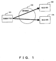
- the technology of performing the broadcasting communications through a packet communications network such as Internet can be a system using a multicast and a unicast.
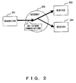
- FIG. 2 shows the broadcasting communications through a multicast.
- a transmitter 201 transmits a packet having a predetermined multicast address
- a network 202 transmits the packet by copying and transmitting the packet according to a predetermined path information, thereby distributing data to a plurality of receivers (203, 204).
- a receiver can receive a packet by entering a receiver group of multicast addresses of a network 2302.
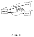
- FIG. 3 shows the broadcasting communications using a unicast. Since the unicast communications are one to one packet communications, a transmitter 301 can realize the broadcasting communications by transmitting the same data to all receivers (303, 304).
- FIG. 4 collectively shows the comparison between a multicast and a unicast in the broadcasting communications.
- the transmitter Relating to the load on the transmitter side, the transmitter transmits a packet only once to a multicast address in the multicast system while a packet is transmitted to each receiver in the unicast system. Therefore, the load on the transmitter side increases proportional to the number of receivers.
- the three items that is, address management, network control, and control on the receiver side, become complicated in the multicast system while they are still simple in the unicast system because they are the same as one to one packet communications.
- the following processes 1) through 3) are basically required. 1) receiving a transmission request from a receiver (receiver management), 2) preparing transmission data (preparing data), 3) transmitting data according to communications procedure such that a different communications condition can be satisfied for each receiver (transmitting process).
- the data portion occupying the majority of a packet is the same regardless of a receiver in the broadcasting communications.
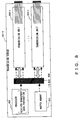
- a packet header, etc. is different, all packet data has to be transferred to each receiver. Therefore, a different packet is generated in memory 503 of a transmission server 501 for each receiver, and is transferred to NICs (corresponding to a network interface card, and a network adapter) 505 and 506 connected to an I/O bus 504.
- NICs corresponding to a network interface card, and a network adapter
- the transmitting process is a real time process
- the real time process cannot be guaranteed when the number of simultaneously connected receivers increases, thereby failing in obtaining predetermined transmission quality. That is, to adjust the transmission quality, at least the following a) through c) are typical examples of parameters to be changed for each receiver. Accordingly, it is difficult to individually control the receivers when the number of simultaneously connected receivers increases.
- the rate of the network on the transmission server side is normally high while the rate of the network on the receiver side is low in most cases. Therefore, if the transmission server intermittently transmits data, the receiver may not be able to receive the data transmitted collectively and intermittently. The discard of data due to the congestion can occur in a network from a transmission server to a receiver. Therefore, smoothly transmitting data from the transmission server can improve the transmission quality.
- a transmission server which is an information processing device of a transmitter, not only increasing the number of receivers who can simultaneously receive a service, but also preventing the transmission quality from being reduced.
- the processor load of a transmission server and the I/O path load are to be reduced so that the transmission quality can be adjusted at a request of a receiver.
- An embodiment of the present invention can provide a transmission unit corresponding to the network adapter connected to the I/O bus of a transmission server, and transmission server generates and transmits a packet corresponding to each receiver according to the information about a receiver and the transmission data provided from the processor of the transmission server through the connection unit to the I/O bus.
- the transmission unit includes: a transmission schedule unit for controlling a transmission schedule including a packet transmission order and packet timing; a receiver information management unit for managing the information about the receiver; a buffer unit for storing and managing the transmission data; and a packet unit for generating and transmitting a packet to a specified receiver according to the transmission schedule.
- the processor of the transmission server performs receiver management, transfers the data once to be transmitted to the transmission unit connected to the I/O bus, and can reduce the processor load of the transmission server and the I/O bus load. Furthermore, the transmission quality can be adjusted at a request of a receiver to generate and transmit a packet for each receiver.
- the system of reducing the load of the information processing device on the transmission side in the broadcasting communications through a unicast is referred to in the following explanation of the embodiments of the present invention. It is also applicable to the broadcasting communications through a multicast, and is especially effective for a high-speed data broadcast.
- FIG. 6 shows the configuration indicating one principle of the present invention.
- a transmission server 601 which is an information processing device for realizing an embodiment of the present invention comprises a processor 602, buffer memory 603, an I/O bus 604, and a transmission unit 605.
- the transmission unit 605 comprises a transmitting process unit 606 for controlling the generation and transmission of a packet, buffer memory 607 for holding transmission data provided by the processor 602, and an NIC 608 for connection to a network.
- the processor 602 manages receivers, and transfers the data stored in the buffer memory 603 to be transmitted to the transmission unit 605 connected to the I/O bus 604 through, for example, a connection unit such as a PCI, etc.
- the transferred data is held in the buffer memory 607 of the transmission unit 605.
- the transmitting process unit 606 generates a packet for each receiver according to receiver information, and transmits it to a network through the NIC 608.
- FIG. 7 shows the flow of the process of the transmission server 601 shown in FIG. 6.
- the process of the transmission server 601 is performed mainly by the transmitting process unit 606, not by the processor 602.
- the processor 602 issues an instruction to transmit data (S701).
- the receiver management information (S702) and transmission data (S703) are transferred to the transmission unit 605.
- the transmission unit 605 determines transmission data has been transmitted to all receivers (S704), and the process terminates if YES. If NO, a transmission schedule is generated and managed (S705), a packet header is generated, a packet is generated from a packet header and the transmission data fetched in S703, and a preparation is made for transmitting the packet (S706). Then, the packet is transmitted (S707) and control is returned to S704.
- FIG. 8 shows a transmission server 601-1 provided with a plurality of transmission units 605-1 through 605-n.
- FIG. 8 shows the same configuration as FIG. 6 except the plurality of transmission units 605-1 through 605-n.
- FIG. 9 shows the flow of the process of the transmission server 601-1 shown in FIG. 8.
- the processor 602 issues an instruction to transmit data (S901).
- the receiver management information (S902) and the transmission data (S903) are transferred to the transmission units 605-1 through 605-n. Since each of the transmission units 605-1 through 605-n performs the same process, the process S908 of the transmission unit 605-1 is described below.
- the transmission schedule is generated and managed (S905), a packet header is generated, a packet is generated from the packet head and the transmission data fetched in S903, and a preparation is made for transmitting the packet (S906). Then, the packet is transmitted (S907) and control is returned to S904.
- the transmission server 601 shown in FIG. 6 can be further designed such that the transmission unit 605 can be replaced with an input transmission unit 1001 provided with a transmission data input device 1002 for obtaining the transmission data.
- the processor 602 only manages receivers, and the receiver management information is the only data transferred through the I/O bus 604.
- the transmission data is obtained by the transmission data input device 1002 such as a camera, etc., and is held in the buffer memory 607.
- the transmitting process unit 606 generates a packet for each receiver according to the receiver information, and transmits the generated packet to a network through the NIC 608.
- FIG. 11 shows the flow of the process of the transmission sever 601-2 shown in FIG. 10.
- the processor 602 issues an instruction to transmit data (S1101).
- the receiver management information (S1102) is transferred to the input transmission unit 1001.
- the input transmission unit 1001 determines whether or not transmission data has been transmitted to all receivers (S1103), and the process terminates if YES. If NO, the transmission schedule is generated and managed (S1104), a packet header is generated, a packet is generated from the packet header and the transmission data (S1106) fetched by the external input device (S1105), and a preparation is made for transmitting the packet (S1107). Then, the packet is transmitted (S1108), and control is returned to S1103.
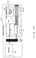
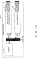
- the input transmission unit 1001 of the transmission sever 601-2 shown in FIG. 10 can collectively input and transmit transmission data, but the number of receivers who can be simultaneously processed is limited by the capability of the input transmission unit 1001. Then, at least one input transmission unit 1202 and a plurality of transmission units or input transmission units 1201 are provided, and transmission data is transferred from one input transmission unit 1202 to another transmission unit or input transmission unit 1201 through an I/O bus, thereby improving the performance of the transmission server (FIG. 12).
- the processor 602 controls, as a part of the process of the receiver management, from where to where the transmission data is to be transferred.
- Transmission data can be the data stored in a disk or a file system, and can be fetched from an input device such as a camera, etc. Since the information processing device to which the present invention is applied can obtain transmission data in any method using the existing technology. The detailed explanation of the technology is omitted here.
- RTP Real-time Transport Protocol
- RFC1889 used as a communications protocol in Internet
- the present invention is not applied exclusively to the RTP.
- the transmission server is an information processing device provided with an I/O bus such as a processor, buffer memory, a PCI bus, etc.
- the transmission unit 605 shown in FIG. 6, etc. is connected to the I/O bus 604 through the connection unit such as a PCI, etc.
- the transmission unit 605 is mounted on the I/O bus 604, and requires a processor much more specifically capable of performing a transmitting process than a processor of a server for physically limiting the cost, installation area, etc.
- a high-speed process can be realized by providing an exclusive mechanism depending on the process contents.
- the transmission unit 605 holds the receiver information specified by the processor of the transmission server, buffers transmission data, and transmits a packet according to the specified communications condition. There are several methods to realize this mainly based on the following mechanism.
- FIG. 13 shows the detailed configuration of the transmission unit 605.
- the transmission unit 605 comprises a control unit 1301, a transmission schedule unit 1302, a receiver information table unit 1303, a buffer unit 1304, and a packet unit 1305.
- a receiver management information 1307 is provided from the processor 602 of the transmission server 601 to the control unit 1301.
- a transmission data 1308 is provided for the buffer unit 1304.
- the transmission schedule unit 1302 manages the transmission schedule
- the receiver information table unit 1303 manages the information about each receiver.
- the packet unit 1305 generates a packet 1306 based on the transmission data of the buffer unit 1304 and the information about the receiver, and transmits the packet. Each unit is described below.
- the control unit 1301 communicates information with the processor 602 of the transmission server 601, controls the entire system including the inside of the transmission unit 605, the network, etc. As shown in FIG. 13, the control unit 1301 provides the receiver management information and the transmission schedule for the transmission schedule unit 1302. It also generates a transmission schedule according to the receiver management information 1307 provided by the processor 602 of the transmission server 601.
- the control unit 1301 can be configured by a less expensive controlling microprocessor and software.
- the transmission schedule unit 1302 manages the information prescribing the order and timing of transmitting transmission data to a receiver.
- the buffer unit 1304 transmits each packet according to the information (the buffer unit 1304 is described below in detail).
- the transmission schedule can be provided as a part of the receiver management information 1307, or can be independently generated by the control unit 1301.
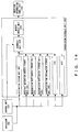
- FIG. 14 shows the detailed configuration of the transmission schedule unit 1302.
- the transmission schedule unit 1302 comprises storage units such as a destination storage unit 1401, a receiver information address storage unit 1402, a transmission data address storage unit 1403, a transmission data length storage unit 1404, a transmission time information storage unit 1405, etc. (1406 and 1407 denote portions for storing other information), a schedule unit 1408, and a memory module unit 1409.
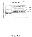
- FIG. 15 shows an example of the configuration of the memory module unit 1409.
- the information to be transmitted to each receiver is stored as transmission 1 (1501), transmission 2 (1502), ...
- a receiver information address 1503 is a receiver information address and identifier of the receiver information table unit 1303.
- a transmission data address 1504 stores data to be transferred in the transmission data stored in the buffer unit 1304.
- a transmission data length 1505 is a data length to be transmitted in the current process.
- a transmission time 1506 is time information to be transmitted in the current process. For example, if the time transmitted in the previous process and the time to be transmitted in the next process are stored, the time information can be transmitted at predetermined time intervals.
- the information stored in the memory module unit 1409 is provided in a predetermined order and timing for the packet unit 1305.
- FIG. 16 shows an example of adjusting a transmission schedule.
- FIG. 16 shows only important units of the memory module unit 1409, that is, a table containing a destination, a time parameter, and a data length.
- the time parameter indicates a packet transmission time interval as the information about the time of previous transmission and the time of subsequent transmission.
- the transmission schedule unit 1302 adjusts the transmission schedule when it receives an instruction to change the destination from the processor 602 or the control unit 1301. For example, as shown in FIG. 16, when an instruction to insert a destination D is issued, the information about the receiver corresponding to the destination D is stored in a destination storage unit 901, a receiver information address storage unit 902, the transmission data address storage unit 1403, the transmission data length storage unit 1404, and the transmission time information storage unit 1405.
- the schedule unit 1408 obtains the place where the destination D is inserted according to the receiver information table unit 1303 or the receiver information management table, and updates the memory module unit 1409. In FIG. 16, the destination D is inserted between the destinations A and B. Similarly, a destination can be deleted. In FIG.
- the schedule unit 1408 deletes the portion relating to the destination B in the memory module unit 1409.
- the receiver information table unit 1303 stores and manages information about each receiver in the receiver information table, and the packet unit 1305 generates a packet according to the information, and transmits it to a network
- FIG. 17 shows an example of the configuration of the receiver information management table.
- Receiver information 1 (1704) and receiver information 2 (1705) about each receiver store the network address of a receiver, the protocol being used, network control information, etc.
- the packet header pattern 1707 stores information to be defined as fixed information after being converted into a packet format when the receiver information is first set. Thus, when the packet unit 1305 generates a packet according to the receiver information, the information converted into the packet format can be used. Therefore, the process can be efficiently performed.
- the change information list 1706 shows a list of a packet length, a checksum for error detection, a sequence number, a time stamp value, etc. defined depending on the protocol to be changed for each packet.
- the information required as a packet header is an IP header, a UDP header, an RTP header (RTP/IPv4).
- the information variable for each packet of a receiver is shown as the shadowed portions shown in FIG. 18.
- Other portions are fixed information.
- the fixed information portion is stored in the receiver information management table as a packet formed by a header and data. Each time the information about a changed portion is computed and updated by the packet unit 1305 based on the change information list 1706.
- the buffer unit 1304. stores transmission data which is the raw data transferred from the processor 602 of the transmission server, or the raw data obtained by the transmission data input device 1002.
- the packet unit 1305 reads data from the buffer unit 1304, and generates a packet. Normally, the data transfer length depends on each receiver. However, according to an embodiment of the present invention, transmission data is divided into blocks such that the packet unit 1305 can easily generate packets of different data transfer length from the transmission data, and auxiliary information is provided.
- FIG. 19 shows an example of the configuration of the buffer unit 1304.
- Transmission data is divided into and held as data blocks such as data 1 (1902) , data 2 (1903), etc.
- a transmission data block length 1904 is a data length of the block.
- a reference counter 1905 refers to the number of the block from the item scheduled to be transmitted by the transmission schedule unit 1302. If the reference number is not 0, the transmission is not completely performed on the data block. If it is 0, then the block can be overwritten.
- a block checksum 1906 is a result of computing a sum of complements of 1 in a 16-bit unit from the data of the block. For example, the IP checksum value of two data blocks can be obtained by the sum of complements of 1 from block checksum values. Therefore, the packet unit 1305 can obtain the checksum value without computing all data.
- a transmission data block 1907 stores data. Described below in detail are the management of transmission data in the buffer unit 1304 (FIG. 20), and the block checksum 1906 (FIG. 21).
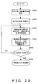
- FIG. 20 is a flowchart of the management of transmission data by the buffer unit 1304.
- the processor 602 provides transmission data in S2001
- the transmission data is divided.
- the reference counter 1905 is initialized in S2002.
- the transmission schedule unit 1302 refers to the data block from the transmission schedule unit 1302 in S2003
- the corresponding reference counter 1905 is increased by 1
- the reference counter 1905 is decreased by 1 when the corresponding data block is completely transmitted in S2004. It is determined in S2005 whether or not the reference counter 1905 is 0. If it is not 0, control is returned to S2003. If it is 0, then the data in the data block is discarded for storage of new data.
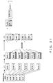
- FIG. 21 shows the method of the packet unit 1305 computing the checksum value of packets from the block checksum.
- the transmission data is divided in (1).
- a checksum is computed for each of the divided data blocks in (2). This is a result of obtaining a sum of complements of 1 in a 16-bit unit.
- the packet unit 1305 obtains a checksum value.
- (3)a shows the process of transmitting blocks 1 and 2 in one packet.
- the checksum ⁇ is obtained by computing a sum of complements of 1 from the checksum of the blocks 1 and 2.
- (3)b shows the process of transmitting the block 2 in one packet.
- the checksum ⁇ shows the checksum of the block 3 as is.
- (3)c chows the process of transmitting the blocks 4, 5, and 6 in one packet.
- the checksum ⁇ is obtained by computing a sum of complements of 1 from the checksum of the blocks 4, 5, and 6.
- (3)d shows the process of transmitting the block 1 and a part of the block 2 (block 2-1) in one packet.
- the checksum ⁇ is obtained by first obtaining the checksum of the block 2-1, and then adding the result to the checksum of the block 1.
- the packet unit 1305 obtains a checksum, it is computed for each packet from the already obtained checksum of each block, thereby efficiently performing a process.
- the packet unit 1305 generates a packet based on the transmission data stored in the buffer unit 1304 and the receiver information table unit 1303 according to the transmission schedule, and transmits it to a network.
- the process of the packet unit 1305 can be performed at a high speed using an exclusive microprocessor and hardware.
- FIG. 22 shows the detailed configuration of the packet unit 1305.
- the packet unit 1305 comprises a receiver information unit 2201, a transmission data unit 2202, a packet transmission schedule unit 2203, a packet generation unit 1704, a processor unit 1705, and a network interface unit 2206.
- the receiver information unit 2201 is connected to the receiver information table unit 1303, the transmission data unit 2202 is connected to the buffer unit 1304, and the packet transmission schedule unit 2203 is connected to the transmission schedule unit 1302.
- the receiver information unit 2201 and the transmission data unit 2202 are configured by buffer memory, and store data.
- a packet generation unit 2204 obtains the packet header of the receiver from the receiver information unit 2201, similarly obtains transmission data from the transmission data unit 2202, and combines them as a packet.
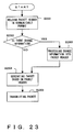
- the packet header contains a fixed portion and a changed portion, it is determined in S2302 whether or not there is change information as shown in FIG. 23. If there is change information, the change information is processed into a packet header in S2303, and a packet is generated based on the packet header in S2304. The generated packet is transmitted to a network through the network interface unit 2206 (S2305).
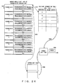
- FIG. 24 shows the interlocking process of each portion in the transmission unit 605.
- a packet is transmitted to a receiver corresponding to the transmission 1 of the memory module unit 1409 of the transmission schedule unit 1302 shown in FIG. 24 (2401).
- Identification information 2402 for obtaining the receiver information corresponding to the transmission 1 indicates A of the receiver information table unit 1303.
- Identification information 2403 indicates the address in the buffer unit 1304.
- the packet transmission schedule unit 2203 of the packet unit 1305 If the packet transmission schedule unit 2203 of the packet unit 1305 is provided with the transmission schedule 'transmitting to the transmission 1', then the packet unit 1305 obtains the corresponding packet header from the receiver information table unit 1303 through the receiver information unit 2201 (2404), and similarly obtains the corresponding transmission data through the transmission data unit 2202 (2405). Then, the packet generation unit 2204 combines the packet header with the transmission data, generates the packet 1306, and transmits it to a network. The computation for a changed portion of the packet header obtained from the receiver information table unit 1303 is performed by the packet generation unit 2204.
- the process of the processor of the transmission server only includes the receiver management, the data preparation, and the primary transmission to each network adapter.
- the receiver management is proportional to the number X of receivers
- the data preparation is made only once per transmission data type
- the primary transmission of data is proportional to K.
- every process is proportional to X.
- the processor load in the present system is equal to or smaller than K/X.
- the process load of the transmission server can be reduced, and the transmitting process performed in real time in most cases can be distributed to a plurality of network adapters. Therefore, the process load of each network adapter can be reduced. Furthermore, the load of the I/O bus can be reduced.
- FIG. 25 shows a transmission unit 2501 having the function of processing a received packet.
- the transmitting process unit 606, the transmission data input device 1002, the buffer memory 607, and the NIC 608 of the transmission unit 2501 have been described above.
- the received packet is transmitted from the NIC 608 to a receiving process unit 2502, and an identifying unit 2503 determines whether or not the packet can be processed in the transmission unit 2501. If it cannot be processed, then it is transmitted to the server processor. If it can be processed, then it is processed in the transmission unit 2501.
- the transmission unit 605 can be extended such that the unit can process a received packet.
- the processes performed by the transmission unit 605 are not limited to the processes described above. That is, the transmission unit 605 can execute various types of software as an intelligent NIC (network interface card) as shown in FIG. 26.
- a transmission unit 2602 of a transmission server 2601 includes a server function A 2604, a server function B 2605, and a server function C 2606 which correspond to the software executed in the transmission unit 2602.
- the hardware such as the processor, the I/O bus, etc. of the transmission server 2601 is included in other hardware 2607.
- the load, etc. of the processor of the transmission server 2601 can be reduced by the transmission unit 2602 executing the software other than the streaming process.
- the transmission server on the transmission side in the broadcasting communications can increase the number of receivers who can be simultaneously provided with services without lowering the transmission quality.
- the processor load and the I/O load of the transmission server can be reduced with the transmission quality appropriately adjusted for each receiver.
Landscapes
- Engineering & Computer Science (AREA)
- Computer Networks & Wireless Communication (AREA)
- Signal Processing (AREA)
- Data Exchanges In Wide-Area Networks (AREA)
- Two-Way Televisions, Distribution Of Moving Picture Or The Like (AREA)
Applications Claiming Priority (2)
| Application Number | Priority Date | Filing Date | Title |
|---|---|---|---|
| JP2001231361 | 2001-07-31 | ||
| JP2001231361A JP4782951B2 (ja) | 2001-07-31 | 2001-07-31 | 放送型通信システム |
Publications (3)
| Publication Number | Publication Date |
|---|---|
| EP1282264A2 true EP1282264A2 (fr) | 2003-02-05 |
| EP1282264A3 EP1282264A3 (fr) | 2004-01-14 |
| EP1282264B1 EP1282264B1 (fr) | 2007-04-11 |
Family
ID=19063429
Family Applications (1)
| Application Number | Title | Priority Date | Filing Date |
|---|---|---|---|
| EP20020250965 Expired - Lifetime EP1282264B1 (fr) | 2001-07-31 | 2002-02-12 | Procédé et dispositif de multidiffusion |
Country Status (4)
| Country | Link |
|---|---|
| US (1) | US7161940B2 (fr) |
| EP (1) | EP1282264B1 (fr) |
| JP (1) | JP4782951B2 (fr) |
| DE (1) | DE60219395T2 (fr) |
Cited By (1)
| Publication number | Priority date | Publication date | Assignee | Title |
|---|---|---|---|---|
| FR2906954A1 (fr) * | 2006-10-10 | 2008-04-11 | Tdf Sa | Procede de retardement temporel de flux de contenus numeriques,dispositif,et produit programme d'ordinateur correspondants. |
Families Citing this family (7)
| Publication number | Priority date | Publication date | Assignee | Title |
|---|---|---|---|---|
| KR100449742B1 (ko) * | 2002-10-01 | 2004-09-22 | 삼성전자주식회사 | 멀티미디어 방송 송수신 장치 및 방법 |
| DE60328303D1 (de) * | 2002-10-16 | 2009-08-20 | Panasonic Corp | Chipkarte, datentransfereinrichtung, datentransfer |
| US8386630B1 (en) * | 2007-09-09 | 2013-02-26 | Arris Solutions, Inc. | Video-aware P2P streaming and download with support for real-time content alteration |
| JP2011211618A (ja) * | 2010-03-30 | 2011-10-20 | Sony Corp | 送信装置、送信方法およびプログラム |
| JP5867206B2 (ja) * | 2012-03-16 | 2016-02-24 | 富士通株式会社 | 移動制御装置,プログラム及びストレージ装置 |
| RU2589867C2 (ru) * | 2012-03-28 | 2016-07-10 | Нек Корпорейшн | Устройство связи, устройство управления, система связи, способ связи, способ управления устройством связи и программа |
| WO2015125405A1 (fr) * | 2014-02-19 | 2015-08-27 | ソニー株式会社 | Appareil de capture d'image, procédé de capture d'image et système de capture d'image |
Family Cites Families (14)
| Publication number | Priority date | Publication date | Assignee | Title |
|---|---|---|---|---|
| JP2841904B2 (ja) * | 1991-03-29 | 1998-12-24 | 株式会社日立製作所 | 高効率マルチキャスト方式 |
| US5764895A (en) * | 1995-01-11 | 1998-06-09 | Sony Corporation | Method and apparatus for directing data packets in a local area network device having a plurality of ports interconnected by a high-speed communication bus |
| JP3123012B2 (ja) * | 1995-03-02 | 2001-01-09 | 松下電器産業株式会社 | マルチメディアサーバー |
| US6282578B1 (en) * | 1995-06-26 | 2001-08-28 | Hitachi, Ltd. | Execution management method of program on reception side of message in distributed processing system |
| JPH0974410A (ja) * | 1995-09-04 | 1997-03-18 | Sumitomo Electric Ind Ltd | 通信中継装置 |
| US6061730A (en) * | 1995-11-13 | 2000-05-09 | Billings; Roger E. | Methods and apparatus for communicating data in computer networks with separate packet assembly and packet broadcast channels |
| JP3862321B2 (ja) * | 1996-07-23 | 2006-12-27 | キヤノン株式会社 | サーバ及びその制御方法 |
| JPH10242962A (ja) * | 1997-02-25 | 1998-09-11 | Nippon Telegr & Teleph Corp <Ntt> | インターネット上のマルチキャストゲートウェイ通信方法及びシステム |
| US6308218B1 (en) * | 1997-09-17 | 2001-10-23 | Sony Corporation | Address look-up mechanism in a multi-port bridge for a local area network |
| JPH11168492A (ja) * | 1997-12-03 | 1999-06-22 | Hitachi Cable Ltd | ルータの中継方法及びルータ装置 |
| JP3266139B2 (ja) * | 1999-04-13 | 2002-03-18 | 日本電気株式会社 | スケジューリング装置 |
| JP3557946B2 (ja) * | 1999-05-21 | 2004-08-25 | 日本電気株式会社 | パケット交換装置 |
| GB0100535D0 (en) * | 2001-01-09 | 2001-02-21 | Lucas Industries Ltd | Method of and apparatus for transmitting data in a distributed processor system |
| US8218555B2 (en) * | 2001-04-24 | 2012-07-10 | Nvidia Corporation | Gigabit ethernet adapter |
-
2001
- 2001-07-31 JP JP2001231361A patent/JP4782951B2/ja not_active Expired - Fee Related
-
2002
- 2002-02-07 US US10/067,295 patent/US7161940B2/en not_active Expired - Lifetime
- 2002-02-12 DE DE2002619395 patent/DE60219395T2/de not_active Expired - Lifetime
- 2002-02-12 EP EP20020250965 patent/EP1282264B1/fr not_active Expired - Lifetime
Cited By (2)
| Publication number | Priority date | Publication date | Assignee | Title |
|---|---|---|---|---|
| FR2906954A1 (fr) * | 2006-10-10 | 2008-04-11 | Tdf Sa | Procede de retardement temporel de flux de contenus numeriques,dispositif,et produit programme d'ordinateur correspondants. |
| WO2008043738A1 (fr) * | 2006-10-10 | 2008-04-17 | Tdf | Procédé de retardement temporel de flux de contenus numériques, dispositif, et produit programme d'ordinateur correspondants |
Also Published As
| Publication number | Publication date |
|---|---|
| JP4782951B2 (ja) | 2011-09-28 |
| US20030026256A1 (en) | 2003-02-06 |
| US7161940B2 (en) | 2007-01-09 |
| DE60219395T2 (de) | 2007-07-19 |
| EP1282264B1 (fr) | 2007-04-11 |
| EP1282264A3 (fr) | 2004-01-14 |
| DE60219395D1 (de) | 2007-05-24 |
| JP2003046564A (ja) | 2003-02-14 |
Similar Documents
| Publication | Publication Date | Title |
|---|---|---|
| EP3313034B1 (fr) | Procédé et dispositif permettant de transmettre un flux de service ethernet flexible | |
| US5781534A (en) | Method and apparatus for determining characteristics of a path | |
| CA2151072C (fr) | Methode de diffusion selective | |
| JP3577393B2 (ja) | 高速データ通信モデム | |
| US6967951B2 (en) | System for reordering sequenced based packets in a switching network | |
| US6321269B1 (en) | Optimized performance for transaction-oriented communications using stream-based network protocols | |
| EP1204249A1 (fr) | Procede et systeme de retransmission de paquets | |
| US20060092910A1 (en) | Method and apparatus for organizing and scheduling multimedia data transfers over a wireless channel | |
| US7120152B2 (en) | Method of routing a packet in a routing device | |
| US20040042456A1 (en) | Method and system for processing data packets | |
| JPWO2001099355A1 (ja) | パケット再送システムおよびパケット再送方法 | |
| US6721335B1 (en) | Segment-controlled process in a link switch connected between nodes in a multiple node network for maintaining burst characteristics of segments of messages | |
| EP3313031B1 (fr) | Procédé et appareil de réalisation d'arp basée sur un réseau défini par logiciel (sdn) | |
| EP1298860A2 (fr) | Méthode et système pour l'association flexible de canaux | |
| CA2495618A1 (fr) | Systeme et procede de gestion de voies dans un reseau radio | |
| US8687530B2 (en) | Stateful scheduling with network coding for roadside-to-vehicle communication | |
| EP4363988B1 (fr) | Dispositif et procédé d'accès direct à une mémoire à distance | |
| EP1282264B1 (fr) | Procédé et dispositif de multidiffusion | |
| Deering et al. | RFC1883: Internet Protocol, version 6 (IPv6) specification | |
| Harold Robinson et al. | SMR: a synchronized multipath re-broadcasting mechanism for improving the quality of conversational video service | |
| JPH02209043A (ja) | フレーム送信方式 | |
| JP2012199728A (ja) | ネットワークシステム、及び通信装置 | |
| JP5728368B2 (ja) | ネットワークシステム、及び通信装置 | |
| US6167058A (en) | Media access control protocol | |
| WO2001001719A1 (fr) | Optimiseur de largeur de bande a fonctionnement dynamique dans des connexions relatives aux radiocommunications, en particulier dans les systemes dect |
Legal Events
| Date | Code | Title | Description |
|---|---|---|---|
| PUAI | Public reference made under article 153(3) epc to a published international application that has entered the european phase |
Free format text: ORIGINAL CODE: 0009012 |
|
| AK | Designated contracting states |
Designated state(s): AT BE CH CY DE DK ES FI FR GB GR IE IT LI LU MC NL PT SE TR |
|
| AX | Request for extension of the european patent |
Extension state: AL LT LV MK RO SI |
|
| PUAL | Search report despatched |
Free format text: ORIGINAL CODE: 0009013 |
|
| AK | Designated contracting states |
Kind code of ref document: A3 Designated state(s): AT BE CH CY DE DK ES FI FR GB GR IE IT LI LU MC NL PT SE TR |
|
| AX | Request for extension of the european patent |
Extension state: AL LT LV MK RO SI |
|
| 17P | Request for examination filed |
Effective date: 20040428 |
|
| AKX | Designation fees paid |
Designated state(s): DE FR GB |
|
| 17Q | First examination report despatched |
Effective date: 20051006 |
|
| GRAP | Despatch of communication of intention to grant a patent |
Free format text: ORIGINAL CODE: EPIDOSNIGR1 |
|
| GRAS | Grant fee paid |
Free format text: ORIGINAL CODE: EPIDOSNIGR3 |
|
| GRAA | (expected) grant |
Free format text: ORIGINAL CODE: 0009210 |
|
| AK | Designated contracting states |
Kind code of ref document: B1 Designated state(s): DE FR GB |
|
| REG | Reference to a national code |
Ref country code: GB Ref legal event code: FG4D |
|
| REF | Corresponds to: |
Ref document number: 60219395 Country of ref document: DE Date of ref document: 20070524 Kind code of ref document: P |
|
| ET | Fr: translation filed | ||
| PLBE | No opposition filed within time limit |
Free format text: ORIGINAL CODE: 0009261 |
|
| STAA | Information on the status of an ep patent application or granted ep patent |
Free format text: STATUS: NO OPPOSITION FILED WITHIN TIME LIMIT |
|
| 26N | No opposition filed |
Effective date: 20080114 |
|
| REG | Reference to a national code |
Ref country code: FR Ref legal event code: PLFP Year of fee payment: 15 |
|
| REG | Reference to a national code |
Ref country code: FR Ref legal event code: PLFP Year of fee payment: 16 |
|
| REG | Reference to a national code |
Ref country code: FR Ref legal event code: PLFP Year of fee payment: 17 |
|
| PGFP | Annual fee paid to national office [announced via postgrant information from national office to epo] |
Ref country code: GB Payment date: 20190206 Year of fee payment: 18 Ref country code: FR Payment date: 20190111 Year of fee payment: 18 Ref country code: DE Payment date: 20190129 Year of fee payment: 18 |
|
| REG | Reference to a national code |
Ref country code: DE Ref legal event code: R119 Ref document number: 60219395 Country of ref document: DE |
|
| GBPC | Gb: european patent ceased through non-payment of renewal fee |
Effective date: 20200212 |
|
| PG25 | Lapsed in a contracting state [announced via postgrant information from national office to epo] |
Ref country code: DE Free format text: LAPSE BECAUSE OF NON-PAYMENT OF DUE FEES Effective date: 20200901 Ref country code: GB Free format text: LAPSE BECAUSE OF NON-PAYMENT OF DUE FEES Effective date: 20200212 Ref country code: FR Free format text: LAPSE BECAUSE OF NON-PAYMENT OF DUE FEES Effective date: 20200229 |