EP1282276A1 - Verfahren und Vorrichtung zur Kanalsresourcenzuweisung - Google Patents
Verfahren und Vorrichtung zur Kanalsresourcenzuweisung Download PDFInfo
- Publication number
- EP1282276A1 EP1282276A1 EP01118415A EP01118415A EP1282276A1 EP 1282276 A1 EP1282276 A1 EP 1282276A1 EP 01118415 A EP01118415 A EP 01118415A EP 01118415 A EP01118415 A EP 01118415A EP 1282276 A1 EP1282276 A1 EP 1282276A1
- Authority
- EP
- European Patent Office
- Prior art keywords
- packet
- header
- routing
- routing information
- resource
- Prior art date
- Legal status (The legal status is an assumption and is not a legal conclusion. Google has not performed a legal analysis and makes no representation as to the accuracy of the status listed.)
- Granted
Links
- 238000000034 method Methods 0.000 title claims abstract description 19
- 238000013468 resource allocation Methods 0.000 title 1
- 238000013507 mapping Methods 0.000 claims abstract description 27
- 230000006837 decompression Effects 0.000 claims description 13
- 238000012545 processing Methods 0.000 claims description 7
- 238000013144 data compression Methods 0.000 claims description 3
- 239000000284 extract Substances 0.000 abstract description 2
- 238000007906 compression Methods 0.000 description 11
- 230000006835 compression Effects 0.000 description 11
- 238000006243 chemical reaction Methods 0.000 description 9
- 230000006978 adaptation Effects 0.000 description 4
- 101100514842 Xenopus laevis mtus1 gene Proteins 0.000 description 2
- 230000005540 biological transmission Effects 0.000 description 2
- 230000006727 cell loss Effects 0.000 description 2
- 238000012546 transfer Methods 0.000 description 2
- 206010010099 Combined immunodeficiency Diseases 0.000 description 1
- 238000001360 collision-induced dissociation Methods 0.000 description 1
- 230000001934 delay Effects 0.000 description 1
- 238000001514 detection method Methods 0.000 description 1
- 230000000694 effects Effects 0.000 description 1
- 238000005516 engineering process Methods 0.000 description 1
- 238000000605 extraction Methods 0.000 description 1
- 230000002349 favourable effect Effects 0.000 description 1
- 230000006870 function Effects 0.000 description 1
- 238000007726 management method Methods 0.000 description 1
- 238000012856 packing Methods 0.000 description 1
- 230000001629 suppression Effects 0.000 description 1
Images



Classifications
-
- H—ELECTRICITY
- H04—ELECTRIC COMMUNICATION TECHNIQUE
- H04L—TRANSMISSION OF DIGITAL INFORMATION, e.g. TELEGRAPHIC COMMUNICATION
- H04L49/00—Packet switching elements
- H04L49/30—Peripheral units, e.g. input or output ports
- H04L49/3081—ATM peripheral units, e.g. policing, insertion or extraction
-
- H—ELECTRICITY
- H04—ELECTRIC COMMUNICATION TECHNIQUE
- H04L—TRANSMISSION OF DIGITAL INFORMATION, e.g. TELEGRAPHIC COMMUNICATION
- H04L12/00—Data switching networks
- H04L12/54—Store-and-forward switching systems
- H04L12/56—Packet switching systems
-
- H—ELECTRICITY
- H04—ELECTRIC COMMUNICATION TECHNIQUE
- H04Q—SELECTING
- H04Q11/00—Selecting arrangements for multiplex systems
- H04Q11/04—Selecting arrangements for multiplex systems for time-division multiplexing
- H04Q11/0428—Integrated services digital network, i.e. systems for transmission of different types of digitised signals, e.g. speech, data, telecentral, television signals
- H04Q11/0478—Provisions for broadband connections
-
- H—ELECTRICITY
- H04—ELECTRIC COMMUNICATION TECHNIQUE
- H04L—TRANSMISSION OF DIGITAL INFORMATION, e.g. TELEGRAPHIC COMMUNICATION
- H04L12/00—Data switching networks
- H04L12/54—Store-and-forward switching systems
- H04L12/56—Packet switching systems
- H04L12/5601—Transfer mode dependent, e.g. ATM
- H04L2012/5638—Services, e.g. multimedia, GOS, QOS
- H04L2012/5646—Cell characteristics, e.g. loss, delay, jitter, sequence integrity
- H04L2012/5652—Cell construction, e.g. including header, packetisation, depacketisation, assembly, reassembly
- H04L2012/5653—Cell construction, e.g. including header, packetisation, depacketisation, assembly, reassembly using the ATM adaptation layer [AAL]
- H04L2012/5656—Cell construction, e.g. including header, packetisation, depacketisation, assembly, reassembly using the ATM adaptation layer [AAL] using the AAL2
Definitions
- the invention relates to the transport of data over a packet switching network in which data is carried in small packets multiplexed into larger data units, such as in ATM using the ATM Adaptation Layer 2.
- the invention has particular relevance to the mapping of voice data carried over an ATM trunk to a limited number of resource devices.
- Asynchronous transfer mode is a protocol-independent, cell-switching technology that offers quality of service guarantees for the support of voice, data and video traffic.
- ATM uses a layered protocol model.
- the ATM Adaptation Layer provides the necessary services to support the higher-level protocols and can exist in end stations or in network switches of a link or network. This layer assures a number of tasks including segmenting the information into 53-byte cells and reassembling it back into its original format.
- AAL2 The asynchronous transfer mode adaptation layer 2 (AAL2) protocol was first defined in the ITU-T Recommendation 1.363.2 in 1997 and is the most favourable of the protocols for supporting low and variable bit rate (LBR/VBR) voice-over-ATM.
- LBR/VBR variable bit rate
- VBR Variable bit rate
- AAL2 enables multiple user channels on a single ATM virtual circuit or virtual channel connection (VCC) and varying traffic conditions for each individual user or channel.
- VCC virtual circuit or virtual channel connection
- the structure of AAL2 also provides for the packing of short length packets (or packet segments) into one ATM cell. This protocol thus offers a variable payload within cells and across cells which provides good bandwidth efficiency.
- AAL2 is the most suitable protocol for voice traffic, since it provides low packetisation delay which enables an operator to provide adequate quality of service to the user, and also allows the efficient use of bandwidth, which is of economic importance to many telephone operators who have leased lines in their networks.
- All AAL protocols define a cell header that includes routing information in the form of a virtual path (VP) and virtual channel (VC) identifier.
- the AAL2 permits information from several channels to be carried in a single ATM cell.
- the cell payload may contain multiple AAL2 packets, each of which has a packet header including a 'connection identifier' (CID) that identifies the individual AAL2 channels.
- CID consists of 8 bits, so theoretically 256 different AAL2 user channels could be multiplexed in a single ATM virtual channel connection (VCC). In practice this number is reduced to 248 since eight identifiers are reserved.
- n x 248 When a number n of ATM virtual channel connections are used identified by the VPI/VCI combination, the total number of user channels available is n x 248. A problem exists when these channels must be processed before reaching the final end destination. For voice applications this processing may involve the compression and decompression of channels to optimise bandwidth utilisation. Providing a resource for compression and decompression for each channel is costly, inefficient and often physically impossible. However, when fewer resources than the total number of user channels are available, some form of mapping is required. Presently available applications use fixed mapping between the VP/VI and CID and resource identity. Fixed mapping may keep delays to a minimum and permit a relatively compact hardware implementation, however, changes in the network may mean that it is impossible to make the most efficient use of all resources.
- the present invention proposes a method and apparatus for allocating units of user data to resource devices when the user data is transmitted in small packets multiplexed onto long packets and both the long and short packets contain routing information relating to each unit of user data.
- a mapping table is provided that contains group identifiers that identify a group of resource devices, providing a receiving unit for receiving long packets, that contain one or more short packets and extracting the routing information. For each unit of data, a first bit sequence of the routing information is used to address the table and obtain a group identifier. Subsequently, a second bit sequence taken from the routing information is concatenated onto the group identifier obtained to generate a resource identifier identifying a single resource device.
- the mapping table is preferably implemented as a writable memory such as a random access memory (RAM) or portion of the same.
- mapping table that contains identifiers for groups of resources as opposed to a single resource and using part of the routing information to address this table and joining a further portion of the routing information to the addressed group identifier the required size of the table can be considerably reduced. Moreover, whilst the mapping between user data and resource devices is fixed within the groups, the table as a whole can be reprogrammed and the allocation for these groups changed freely to best distribute the user data among the resource devices. It will be understood that a long packet may contain only one short packet so that the short packet is only marginally shorter than a long packet.
- routing information that is contained in a header of the long packet is preferably used as one of the column or row addresses, while a portion of the routing information in a header of the short packet is used as the other of the column or row addresses.
- the column address is obtained from information from the short packet header, and vice versa.
- the portion of the routing information contained in the small packet header is preferably taken from the first received bit sequence, i.e.
- the least significant bits while the second bit sequence that is concatenated onto the group identifier is taken from the last received bit sequence, i.e. the most significant bits.
- This second bit sequence is then preferably prefixed to the group identifier to form the most significant bits of the resource identifier.
- the above objects are obtained in an arrangement for mapping user channel identifiers to resources, wherein said user channels are carried as multiplexed packets on multiple trunks and each user channel is allocated a trunk number and a channel number.
- the arrangement includes a receiver for receiving multiplexed packets on a trunk and for extracting a trunk number and a first sequence of bits of a channel number for each packet and also a memory containing words identifying a group of resources that is addressable with the trunk number and the first sequence of bits from the channel number to deliver a word.
- the arrangement further includes an identifier compiler for concatenating a second sequence of bits from the channel number to a word addressed and delivered using said trunk number and the first sequence of bits of said channel number to generate an individual resource identifier.
- ATM provides a means of reducing the bandwidth and other resources required for a single call, moreover ATM Adaptation Layer 2 (AAL2) permits the merging of channels onto a single trunk, so reducing the delay perceived for any single channel.
- AAL2 ATM Adaptation Layer 2
- AAL2 is divided into two sub-layers: the Common Part Sub-layer (CPS) and the Service Specific Convergence Sub-layer (SSCS).
- CPS Common Part Sub-layer
- SSCS Service Specific Convergence Sub-layer
- Fig. 1 shows an ATM cell 100 with a header 110 of 5 octets in length and a payload 110 of 48 octets. The contents of the header 110 will be discussed further with reference to Fig. 2.
- the AAL2 protocol layer defines a CPS protocol data unit (CPS-PDU) consisting of 48 octets, which is carried as the payload 110 of the ATM cell.
- a CPS-PDU 110 consists of a one-octet start field (STF) 130 and at least one CPS packet 140.
- STF one-octet start field
- a CPS packet is made up of a three-octet header 141, shown as the shaded region in Fig. 1, and up to 45 octets of payload data from a single user channel.
- Fig. 1 four CPS packets 140 are contained in the ATM cell 100. This ATM cell 100 thus contains the multiplexed data from four different user channels.
- the start field (STF) 111 in the CPS-PDU 100 contains a 6-bit offset field, which identifies the location of the start of the first CPS packet 140 which starts transmission inside the CPS-PDU 110.
- the start field 130 further includes a parity bit for protecting the start field from errors and a sequence number for identifying cell loss.
- the routing of a CPS packet 140 is defined by two levels of address information.
- a first level of addressing information is contained in the header 110 of the ATM cell; this defines the Virtual Channel Connection (VCC), which will be referred to as a trunk in this document.
- VCC Virtual Channel Connection
- the second level is contained in the CPS packet header 141 and identifies the user channels carried on each ATM trunk.
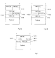
- the structures of the ATM header 110 and the CPS packet headers 141 are illustrated in Figs. 2 and 3, respectively.
- Fig. 2a shows an ATM header for the user-to-network interface (UNI)
- Fig. 2b shows an ATM header for a network-to-network interface (NNI).
- an ATM cell header 110 includes a routing field RF or Virtual Channel Connection (VCC) 1101.
- this routing field 1101 is 24 bits long for use in the UNI, while for NNI the routing field 1101 is 28 bits long as shown in Fig. 2a.
- the routing field is preceded by a 4-bit generic flow control (GFC) field. This field is used only at the UNI to regulate the flow of traffic for different grades of service.
- GFC generic flow control
- the routing field 1101 is followed by a 3-bit field for identifying the payload type PTI 1102, for example whether the cell contains user information or connection management information, a 1-bit Cell Loss Priority (CLP) field 1103 for indicating whether a cell may be discarded in the event of network congestion and a Header Error Check (HEC) field 1104 of eight bits for validating four previous octets of the header information.
- the Routing Field 1101 contains a Virtual Path Identifier/Virtual Channel Identifier (VPI/VCI) combination, which together define the ATM trunk or VCC.
- the RF 1101 specifically consists of an 8-bit VPI and a 16-bit VCI.
- the RF 1101 consists of a 12-bit VPI and 16-bit VCI.
- the CPS packet header 141 contains an 8-bit Connection Identifier (CID) field 1411, a 6-bit Length Identifier (LI) field 1412 indicating the length of the CPS packet, a 5-bit User-to-User Indication (UUI) field 1413 and finally a 5-bit Header Error Check (HEC) field 1414.
- the CID 1411 identifies the user channel represented by the CPS packet. Eight connection identifiers are reserved, thus 248 user channels are permitted per ATM trunk and identified by a CID 1411.
- Fig. 4 schematically illustrates a network node 200 for handling ATM cells in a known number of trunks.
- this node 200 includes a number of resources in the form of data compression/decompression units 220.
- the number of compression/decompression units 220 is less than the total number of user channels available, that is, the combination of the total number of user channels and the total number of ATM trunks.
- ATM cells 100 from any one of the trunks handled by this node 200 are initially intercepted by a conversion unit 210.
- this unit comprises a conversion table 211 and a microprocessor 212 with associated non-shown program memory and i/o devices.
- the microprocessor 212 controls receipt of the ATM cells, extraction of data from these cells, access of the conversion table 211 and also manipulation of data to generate an identifier for the resource devices.
- the microprocessor 212 may be replaced by a control interface that may be used by an external microprocessor or similar unit and hardware implementing the access to the conversion table 211 and subsequent generation of resource identifiers as discussed below.
- the unit 220 extracts information from the Routing Field 1101 of the ATM cell header 110, specifically from the VPI/VCI data, and also the Connection Identifier, CID 1411 from the CPS packet header 141 and with the conversion table 211 uses this information to generate a new identifier that uniquely identifies a resource in the form of a compression/decompression unit 220.
- This resource identifier is denoted an Internal Connection Identifier ICI.
- the conversion unit 210 performs a mapping function to map incoming CPS packets to one of the compression/decompression units 220.
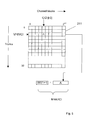
- the mechanism used to perform this mapping is illustrated in Fig. 5.
- the mapping makes use of a mapping table 211, which in the present embodiment is a RAM or other similar writable memory space of defined dimensions.
- Each address location of the RAM 211 contains a word A of length n, which addresses a group of compression/decompression units 220.
- a predetermined group of user channels is allocated to a group of compression/decompression units.
- the rows of this RAM are addressed using specific bits extracted from the Routing Field in the ATM cell header 110.
- This extracted VPI/VCI information 1101 specifies the particular trunk used by the ATM cell. In the present example, it is assumed that the network is operating with 32 trunks. Accordingly, 5 bits of the VPI/VCI are used to identify the trunk. In the present example these 5 bits are the least significant bits of the Routing Field of the ATM cell header and thus comprise bits 0 to 4, which will be referred to as VPI/VCI [4:0]. It will be understood, however, that the required number of bits may be taken from anywhere in the VPI/VCI.
- the columns of the RAM 211 forming the mapping table are addressed using information extracted from the Connection Identifier CID 1411 of the CPS packet header 141.
- This information is a sequence of least significant bits consisting of i+1bits taken from the CID 1411, which will be referred to as CID[i:0].
- the length of this bit sequence i+1, and thus the total number of columns 2 i+1 in the RAM 211 depends on the number of channels or compression/decompression units 220 in a single group.
- the remaining bits of the CID 1411 i.e. bits CID[7:i+1] are prefixed to the word contained in memory to generate a word that uniquely identifies one of the units 220.
- trunk number VPI/VCI 1100 is used to address the table rows while a bit sequence from the CID 1411 is used to address the table columns, it will be appreciated that these may be reversed.
- the remapping table 211 in the RAM is programmable. When used as in the present embodiment for routing call information to data compression and decompression circuitry 220, the table 211 is preferably fixed during a session. Naturally it may be programmed when no session is ongoing, for example when a new trunk or cross-connection is added to the network. By grouping the channel allocation, the remapping table 211 can be kept small, yet still allow flexibility in the mapping of user channels to resources. The effect of grouping the channels is to fix the mapping between a group of channels and a sequence of resource identification numbers or ICIs for a current programmed RAM table 211 configuration. However, since this grouping is known, it is possible to configure the system such that groups of channels contain specific application types.
- the table 211 in the RAM must be m 3 bits in size when the number of resources is between 2 m-1 and 2 m . Grouping the channel allocation such that these are assigned in twos reduces the table 211 to a half of this size, allocating channels in groups of four quarters the table size.
- the procedure starts in step 300 with the receipt by the conversion unit 210 in node 200 of the start of an ATM cell 100.
- the trunk number is obtained by extracting VPI/VCI[4:0], i.e. the five LSBs from the VPI/VCI field in the ATM cell header 110. The trunk number is then used to address one row in the table 211.
- the CID 1411 of the first CPS packet header 141 is read and bits CID[5:0], that is the first six LSBs, used to address a column of memory 211.
- a 7-bit word representing the group identifier A is then read out in step 303.
- step 304 the remaining two MSBs from the CID, that is CID[7:6], are extracted from the CID 1411 and prefixed to the 7-bit word A to generate a 9-bit ICI, which uniquely addresses one of the 512 resources 220.
- step 305 the CPS packet associated with the CID is routed to the resource identified by the Internal Connection Identifier ICI. This terminates the mapping for a CPS packet.
- step 306 the procedure checks whether the ATM cell has been completely received. If not, the procedure returns to step 302 to receive the CID 1411 from a following CPS packet 140. Otherwise the procedure terminates.
- the remapping table 211 is programmed with sequential words A, the user channels on the same trunk and with sequential CID 1411 will be allocated to sequentially addressed resources. It will be understood that the remapping of channels by groups of four as described with reference to Fig. 6 is just one possible configuration of the remapping table. With the described application for 32 trunks and 512 available resources 220, this configuration requires a RAM capacity of 14336 bits for the remapping table 211, and is thus relatively easy to accommodate, while retaining a fair amount of flexibility in the allocation of user channels to resources. However, it is entirely conceivable to perform the channel allocation by pairs of channels to obtain a greater flexibility or to group more than four channels together to reduce the required capacity of the RAM when the number of trunks is very high.
- the sequence of least significant bits (LSB) of the user channel CID 1411 are used to address the columns of the mapping table, while the remaining most significant bits (MSB) of the CID 1411 are then prefixed to the table contents to generate an identifier of the required length.
- the trunk identifier VPI/VCI 1101 is first used to address a whole row of the remapping table 211, while the columns are addressed by a sequence of least significant bits from the CID 1411. This division of the routing information is the most efficient, since it reduces the processing delay.
- the trunk number VPI/VCI 1101 when an ATM cell arrives at the conversion unit 210 the trunk number VPI/VCI 1101 will be received first and thus can be best used to address the required row that will be used for all CPS packets 140 contained in the cell 100.
- the VPI/VCI 1101 is used to identify a sequence of words A in the table 211.
- the least significant bits of the CID 1411 of each CPS packet will be received by the conversion unit first and can be used to address the required column of table 211, i.e. the required word A from the sequence of words addressed by the trunk number VPI/VC/ 1101, and read out the addressed word A whilst the most significant bits of the CID 1411 are being received.
- the combined routing information for each CPS packet made up of the Routing Field 1101 of the ATM header and the CID 1411 from the CPS packet may be used differently to generate the ICI.
- the first received bits (LSBs) of the Routing Field 1100 of the ATM cell may be used to address a row of the table 211, while subsequent bits from this Routing field may be used as the least significant bits of the column address together with the first received bits of each CID contained in the ATM cell 100.
- the grouped allocation of channels may alternatively be achieved by using a bit sequence taken from the MSBs of the CID 1411 to address the table columns and subsequently suffixing the remaining LSBs of the CID 1411 to the end of the addressed word A. In this way, channels with sequential CIDs 1411 will be allocated to sequentially identified resource devices 220 or ICIs.
Landscapes
- Engineering & Computer Science (AREA)
- Computer Networks & Wireless Communication (AREA)
- Signal Processing (AREA)
- Data Exchanges In Wide-Area Networks (AREA)
Priority Applications (2)
| Application Number | Priority Date | Filing Date | Title |
|---|---|---|---|
| DE60130550T DE60130550D1 (de) | 2001-07-31 | 2001-07-31 | Verfahren und Vorrichtung zur Kanalsresourcenzuweisung |
| EP01118415A EP1282276B1 (de) | 2001-07-31 | 2001-07-31 | Verfahren und Vorrichtung zur Kanalsresourcenzuweisung |
Applications Claiming Priority (1)
| Application Number | Priority Date | Filing Date | Title |
|---|---|---|---|
| EP01118415A EP1282276B1 (de) | 2001-07-31 | 2001-07-31 | Verfahren und Vorrichtung zur Kanalsresourcenzuweisung |
Publications (2)
| Publication Number | Publication Date |
|---|---|
| EP1282276A1 true EP1282276A1 (de) | 2003-02-05 |
| EP1282276B1 EP1282276B1 (de) | 2007-09-19 |
Family
ID=8178194
Family Applications (1)
| Application Number | Title | Priority Date | Filing Date |
|---|---|---|---|
| EP01118415A Expired - Lifetime EP1282276B1 (de) | 2001-07-31 | 2001-07-31 | Verfahren und Vorrichtung zur Kanalsresourcenzuweisung |
Country Status (2)
| Country | Link |
|---|---|
| EP (1) | EP1282276B1 (de) |
| DE (1) | DE60130550D1 (de) |
Cited By (2)
| Publication number | Priority date | Publication date | Assignee | Title |
|---|---|---|---|---|
| WO2012019524A1 (zh) * | 2010-08-12 | 2012-02-16 | 华为技术有限公司 | 一种网络连接方法和系统 |
| US8570952B2 (en) | 2004-04-29 | 2013-10-29 | Interdigital Technology Corporation | Method and apparatus for selectively enabling reception of downlink signaling channels |
Citations (2)
| Publication number | Priority date | Publication date | Assignee | Title |
|---|---|---|---|---|
| US5623493A (en) * | 1994-04-21 | 1997-04-22 | Mitsubishi Denki Kabushiki Kaisha | Multiplexer demultiplexer switching device and network adapter |
| WO1999033314A1 (en) * | 1997-12-19 | 1999-07-01 | Telefonaktiebolaget Lm Ericsson (Publ) | Asynchronous transfer mode system handling differing aal protocols |
-
2001
- 2001-07-31 DE DE60130550T patent/DE60130550D1/de not_active Expired - Lifetime
- 2001-07-31 EP EP01118415A patent/EP1282276B1/de not_active Expired - Lifetime
Patent Citations (2)
| Publication number | Priority date | Publication date | Assignee | Title |
|---|---|---|---|---|
| US5623493A (en) * | 1994-04-21 | 1997-04-22 | Mitsubishi Denki Kabushiki Kaisha | Multiplexer demultiplexer switching device and network adapter |
| WO1999033314A1 (en) * | 1997-12-19 | 1999-07-01 | Telefonaktiebolaget Lm Ericsson (Publ) | Asynchronous transfer mode system handling differing aal protocols |
Cited By (6)
| Publication number | Priority date | Publication date | Assignee | Title |
|---|---|---|---|---|
| US8570952B2 (en) | 2004-04-29 | 2013-10-29 | Interdigital Technology Corporation | Method and apparatus for selectively enabling reception of downlink signaling channels |
| US9867228B2 (en) | 2004-04-29 | 2018-01-09 | Interdigital Technology Corporation | Method and apparatus for selectively enabling reception of downlink signaling channels |
| US10368389B2 (en) | 2004-04-29 | 2019-07-30 | Interdigital Technology Corporation | Method and apparatus for selectively enabling reception of downlink signaling channels |
| US11026287B2 (en) | 2004-04-29 | 2021-06-01 | Interdigital Technology Corporation | Method and apparatus for selectively enabling reception of downlink signaling channels |
| WO2012019524A1 (zh) * | 2010-08-12 | 2012-02-16 | 华为技术有限公司 | 一种网络连接方法和系统 |
| US9084263B2 (en) | 2010-08-12 | 2015-07-14 | Huawei Technologies Co., Ltd. | Network connection method and system |
Also Published As
| Publication number | Publication date |
|---|---|
| DE60130550D1 (de) | 2007-10-31 |
| EP1282276B1 (de) | 2007-09-19 |
Similar Documents
| Publication | Publication Date | Title |
|---|---|---|
| US7369555B2 (en) | Channel resource allocation arrangement and method | |
| US6639916B1 (en) | AAL receiving circuit and method of processing ATM cells | |
| US7929569B2 (en) | Compression of overhead in layered data communication links | |
| US6449276B1 (en) | Method and apparatus for efficient switching of partial minicells in ATM adaptation layer 2 | |
| US7054320B1 (en) | Apparatus and method for processing AAL2 which supports multiple virtual channels in mobile communication system | |
| US6317431B1 (en) | ATM partial cut-through | |
| US6603767B1 (en) | Cell exchanging device | |
| US6990105B1 (en) | Transporting multiprotocol datagrams | |
| CA2273224C (en) | Scaleable data network router | |
| EP1282276B1 (de) | Verfahren und Vorrichtung zur Kanalsresourcenzuweisung | |
| CN1152523C (zh) | 信元交换方法及信元交换系统 | |
| US6829241B1 (en) | AAL-2/AAL-5 processing apparatus in mobile communication system | |
| EP0991293B1 (de) | Verfahren und System zur Übertragung von Schmalbandverbindungen über ein ATM-Netz | |
| US8780898B2 (en) | Processor for packet switching between cell streams with optional virtual channel and channel identification modification | |
| JP3842417B2 (ja) | Atmスイッチ | |
| US7403533B2 (en) | AAL2 switching apparatus and method | |
| KR100354163B1 (ko) | 이동 통신 시스템에서 다중 가상 채널을 지원하는 aal2 프로토콜 구현 장치 및 방법 | |
| KR100379377B1 (ko) | 비동기전송모드 셀 라우팅 장치 및 라우팅 방법 | |
| KR100304941B1 (ko) | 다중 가상 채널을 지원하는 aal-2 처리 장치 | |
| JP3246638B2 (ja) | 端末収容装置およびその動作方法 | |
| KR100221330B1 (ko) | 에이에이엘 계층의 분할 및 재결합이들 셀 제거에 의한 잔여 대역폭의 효율적 이용방법 | |
| KR100221332B1 (ko) | 에이에이엘 계층의 분할 및 재결합 부계층에서의 잔여 대역폭의 효율적 이용방법 | |
| KR100221331B1 (ko) | 에이에이엘 계층의 분할 및 재결합 부계층에서의 연결 리스트를 이용한 잔여 대역폭의 효율적 이용방법 | |
| KR0185860B1 (ko) | 에이에이엘 타입 1에서의 고정비트율 데이터 처리장치 및 그처리방법 | |
| KR100221329B1 (ko) | 비동기 전송모드 통신방식 네트워크 인터페이스 카드에서의 실시간 동영상 데이터 처리장치 |
Legal Events
| Date | Code | Title | Description |
|---|---|---|---|
| PUAI | Public reference made under article 153(3) epc to a published international application that has entered the european phase |
Free format text: ORIGINAL CODE: 0009012 |
|
| AK | Designated contracting states |
Designated state(s): AT BE CH CY DE DK ES FI FR GB GR IE IT LI LU MC NL PT SE TR |
|
| AX | Request for extension of the european patent |
Extension state: AL LT LV MK RO SI |
|
| 17P | Request for examination filed |
Effective date: 20030618 |
|
| AKX | Designation fees paid |
Designated state(s): DE FR GB |
|
| RAP1 | Party data changed (applicant data changed or rights of an application transferred) |
Owner name: TELEFONAKTIEBOLAGET LM ERICSSON (PUBL) |
|
| 17Q | First examination report despatched |
Effective date: 20050727 |
|
| GRAP | Despatch of communication of intention to grant a patent |
Free format text: ORIGINAL CODE: EPIDOSNIGR1 |
|
| GRAS | Grant fee paid |
Free format text: ORIGINAL CODE: EPIDOSNIGR3 |
|
| GRAA | (expected) grant |
Free format text: ORIGINAL CODE: 0009210 |
|
| AK | Designated contracting states |
Kind code of ref document: B1 Designated state(s): DE FR GB |
|
| REG | Reference to a national code |
Ref country code: GB Ref legal event code: FG4D |
|
| REF | Corresponds to: |
Ref document number: 60130550 Country of ref document: DE Date of ref document: 20071031 Kind code of ref document: P |
|
| EN | Fr: translation not filed | ||
| PLBE | No opposition filed within time limit |
Free format text: ORIGINAL CODE: 0009261 |
|
| STAA | Information on the status of an ep patent application or granted ep patent |
Free format text: STATUS: NO OPPOSITION FILED WITHIN TIME LIMIT |
|
| PG25 | Lapsed in a contracting state [announced via postgrant information from national office to epo] |
Ref country code: DE Free format text: LAPSE BECAUSE OF FAILURE TO SUBMIT A TRANSLATION OF THE DESCRIPTION OR TO PAY THE FEE WITHIN THE PRESCRIBED TIME-LIMIT Effective date: 20071220 |
|
| ET | Fr: translation filed | ||
| REG | Reference to a national code |
Ref country code: FR Ref legal event code: EERR Free format text: CORRECTION DE BOPI 08/21 - BREVETS EUROPEENS DONT LA TRADUCTION N A PAS ETE REMISE A L INPI. IL Y A LIEU DE SUPPRIMER : LA MENTION DE LA NON-REMISE. LA REMISE DE LA TRADUCTION EST PUBLIEE DANS LE PRESENT BOPI. |
|
| 26N | No opposition filed |
Effective date: 20080620 |
|
| PG25 | Lapsed in a contracting state [announced via postgrant information from national office to epo] |
Ref country code: FR Free format text: LAPSE BECAUSE OF FAILURE TO SUBMIT A TRANSLATION OF THE DESCRIPTION OR TO PAY THE FEE WITHIN THE PRESCRIBED TIME-LIMIT Effective date: 20080523 |
|
| PGFP | Annual fee paid to national office [announced via postgrant information from national office to epo] |
Ref country code: GB Payment date: 20140729 Year of fee payment: 14 Ref country code: FR Payment date: 20140717 Year of fee payment: 14 |
|
| GBPC | Gb: european patent ceased through non-payment of renewal fee |
Effective date: 20150731 |
|
| PG25 | Lapsed in a contracting state [announced via postgrant information from national office to epo] |
Ref country code: GB Free format text: LAPSE BECAUSE OF NON-PAYMENT OF DUE FEES Effective date: 20150731 |
|
| REG | Reference to a national code |
Ref country code: FR Ref legal event code: ST Effective date: 20160331 |
|
| PG25 | Lapsed in a contracting state [announced via postgrant information from national office to epo] |
Ref country code: FR Free format text: LAPSE BECAUSE OF NON-PAYMENT OF DUE FEES Effective date: 20150731 |