EP1282463B1 - Module d'electrodesionisation ameliore - Google Patents
Module d'electrodesionisation ameliore Download PDFInfo
- Publication number
- EP1282463B1 EP1282463B1 EP01926430A EP01926430A EP1282463B1 EP 1282463 B1 EP1282463 B1 EP 1282463B1 EP 01926430 A EP01926430 A EP 01926430A EP 01926430 A EP01926430 A EP 01926430A EP 1282463 B1 EP1282463 B1 EP 1282463B1
- Authority
- EP
- European Patent Office
- Prior art keywords
- anion
- materials
- ion exchange
- channel
- waste
- Prior art date
- Legal status (The legal status is an assumption and is not a legal conclusion. Google has not performed a legal analysis and makes no representation as to the accuracy of the status listed.)
- Expired - Lifetime
Links
- 238000009296 electrodeionization Methods 0.000 title claims abstract description 20
- 239000000463 material Substances 0.000 claims abstract description 99
- 150000001450 anions Chemical class 0.000 claims abstract description 75
- 238000005342 ion exchange Methods 0.000 claims abstract description 71
- 239000012528 membrane Substances 0.000 claims abstract description 65
- 239000002699 waste material Substances 0.000 claims abstract description 55
- 239000011324 bead Substances 0.000 claims abstract description 27
- 150000002500 ions Chemical class 0.000 claims abstract description 24
- 241000894007 species Species 0.000 claims abstract description 17
- 125000000129 anionic group Chemical group 0.000 claims abstract description 10
- 239000000203 mixture Substances 0.000 claims abstract description 6
- 230000000717 retained effect Effects 0.000 claims abstract description 5
- 150000001768 cations Chemical class 0.000 claims description 36
- 239000007788 liquid Substances 0.000 claims description 20
- BVKZGUZCCUSVTD-UHFFFAOYSA-M Bicarbonate Chemical compound OC([O-])=O BVKZGUZCCUSVTD-UHFFFAOYSA-M 0.000 claims description 11
- -1 hydroxyl ions Chemical class 0.000 claims description 11
- 238000005349 anion exchange Methods 0.000 claims description 4
- 239000004744 fabric Substances 0.000 claims description 4
- 239000000835 fiber Substances 0.000 claims description 4
- 239000002245 particle Substances 0.000 claims description 4
- 125000000524 functional group Chemical group 0.000 claims description 3
- 230000001788 irregular Effects 0.000 claims description 3
- 125000002091 cationic group Chemical group 0.000 abstract description 6
- 230000014759 maintenance of location Effects 0.000 abstract description 2
- 229920005989 resin Polymers 0.000 description 21
- 239000011347 resin Substances 0.000 description 21
- XLYOFNOQVPJJNP-UHFFFAOYSA-N water Substances O XLYOFNOQVPJJNP-UHFFFAOYSA-N 0.000 description 13
- CURLTUGMZLYLDI-UHFFFAOYSA-N Carbon dioxide Chemical compound O=C=O CURLTUGMZLYLDI-UHFFFAOYSA-N 0.000 description 8
- 229920001429 chelating resin Polymers 0.000 description 7
- 239000001569 carbon dioxide Substances 0.000 description 4
- 229910002092 carbon dioxide Inorganic materials 0.000 description 4
- 238000001223 reverse osmosis Methods 0.000 description 4
- 239000000126 substance Substances 0.000 description 4
- OYPRJOBELJOOCE-UHFFFAOYSA-N Calcium Chemical compound [Ca] OYPRJOBELJOOCE-UHFFFAOYSA-N 0.000 description 3
- 230000037427 ion transport Effects 0.000 description 3
- 238000004519 manufacturing process Methods 0.000 description 3
- 229910052791 calcium Inorganic materials 0.000 description 2
- 239000011575 calcium Substances 0.000 description 2
- 235000020681 well water Nutrition 0.000 description 2
- 239000002349 well water Substances 0.000 description 2
- NWUYHJFMYQTDRP-UHFFFAOYSA-N 1,2-bis(ethenyl)benzene;1-ethenyl-2-ethylbenzene;styrene Chemical compound C=CC1=CC=CC=C1.CCC1=CC=CC=C1C=C.C=CC1=CC=CC=C1C=C NWUYHJFMYQTDRP-UHFFFAOYSA-N 0.000 description 1
- OKTJSMMVPCPJKN-UHFFFAOYSA-N Carbon Chemical compound [C] OKTJSMMVPCPJKN-UHFFFAOYSA-N 0.000 description 1
- BVKZGUZCCUSVTD-UHFFFAOYSA-L Carbonate Chemical compound [O-]C([O-])=O BVKZGUZCCUSVTD-UHFFFAOYSA-L 0.000 description 1
- 230000004888 barrier function Effects 0.000 description 1
- 239000000292 calcium oxide Substances 0.000 description 1
- 229940087373 calcium oxide Drugs 0.000 description 1
- ODINCKMPIJJUCX-UHFFFAOYSA-N calcium oxide Inorganic materials [Ca]=O ODINCKMPIJJUCX-UHFFFAOYSA-N 0.000 description 1
- 229910052799 carbon Inorganic materials 0.000 description 1
- 238000005266 casting Methods 0.000 description 1
- 230000001934 delay Effects 0.000 description 1
- 230000006866 deterioration Effects 0.000 description 1
- 238000001125 extrusion Methods 0.000 description 1
- 239000000945 filler Substances 0.000 description 1
- 239000003292 glue Substances 0.000 description 1
- 238000010348 incorporation Methods 0.000 description 1
- 239000012500 ion exchange media Substances 0.000 description 1
- 239000003456 ion exchange resin Substances 0.000 description 1
- 229920003303 ion-exchange polymer Polymers 0.000 description 1
- 238000000034 method Methods 0.000 description 1
- 229910001220 stainless steel Inorganic materials 0.000 description 1
- 239000010935 stainless steel Substances 0.000 description 1
Images


Classifications
-
- C—CHEMISTRY; METALLURGY
- C02—TREATMENT OF WATER, WASTE WATER, SEWAGE, OR SLUDGE
- C02F—TREATMENT OF WATER, WASTE WATER, SEWAGE, OR SLUDGE
- C02F1/00—Treatment of water, waste water, or sewage
- C02F1/46—Treatment of water, waste water, or sewage by electrochemical methods
- C02F1/469—Treatment of water, waste water, or sewage by electrochemical methods by electrochemical separation, e.g. by electro-osmosis, electrodialysis, electrophoresis
- C02F1/4693—Treatment of water, waste water, or sewage by electrochemical methods by electrochemical separation, e.g. by electro-osmosis, electrodialysis, electrophoresis electrodialysis
- C02F1/4695—Treatment of water, waste water, or sewage by electrochemical methods by electrochemical separation, e.g. by electro-osmosis, electrodialysis, electrophoresis electrodialysis electrodeionisation
-
- B—PERFORMING OPERATIONS; TRANSPORTING
- B01—PHYSICAL OR CHEMICAL PROCESSES OR APPARATUS IN GENERAL
- B01D—SEPARATION
- B01D61/00—Processes of separation using semi-permeable membranes, e.g. dialysis, osmosis or ultrafiltration; Apparatus, accessories or auxiliary operations specially adapted therefor
- B01D61/42—Electrodialysis; Electro-osmosis ; Electro-ultrafiltration; Membrane capacitive deionization
- B01D61/44—Ion-selective electrodialysis
- B01D61/46—Apparatus therefor
- B01D61/48—Apparatus therefor having one or more compartments filled with ion-exchange material, e.g. electrodeionisation
-
- B—PERFORMING OPERATIONS; TRANSPORTING
- B01—PHYSICAL OR CHEMICAL PROCESSES OR APPARATUS IN GENERAL
- B01J—CHEMICAL OR PHYSICAL PROCESSES, e.g. CATALYSIS OR COLLOID CHEMISTRY; THEIR RELEVANT APPARATUS
- B01J47/00—Ion-exchange processes in general; Apparatus therefor
- B01J47/02—Column or bed processes
- B01J47/06—Column or bed processes during which the ion-exchange material is subjected to a physical treatment, e.g. heat, electric current, irradiation or vibration
- B01J47/08—Column or bed processes during which the ion-exchange material is subjected to a physical treatment, e.g. heat, electric current, irradiation or vibration subjected to a direct electric current
-
- C—CHEMISTRY; METALLURGY
- C02—TREATMENT OF WATER, WASTE WATER, SEWAGE, OR SLUDGE
- C02F—TREATMENT OF WATER, WASTE WATER, SEWAGE, OR SLUDGE
- C02F1/00—Treatment of water, waste water, or sewage
- C02F1/42—Treatment of water, waste water, or sewage by ion-exchange
-
- C—CHEMISTRY; METALLURGY
- C02—TREATMENT OF WATER, WASTE WATER, SEWAGE, OR SLUDGE
- C02F—TREATMENT OF WATER, WASTE WATER, SEWAGE, OR SLUDGE
- C02F1/00—Treatment of water, waste water, or sewage
- C02F1/46—Treatment of water, waste water, or sewage by electrochemical methods
- C02F1/4604—Treatment of water, waste water, or sewage by electrochemical methods for desalination of seawater or brackish water
-
- C—CHEMISTRY; METALLURGY
- C02—TREATMENT OF WATER, WASTE WATER, SEWAGE, OR SLUDGE
- C02F—TREATMENT OF WATER, WASTE WATER, SEWAGE, OR SLUDGE
- C02F1/00—Treatment of water, waste water, or sewage
- C02F1/46—Treatment of water, waste water, or sewage by electrochemical methods
- C02F1/469—Treatment of water, waste water, or sewage by electrochemical methods by electrochemical separation, e.g. by electro-osmosis, electrodialysis, electrophoresis
- C02F1/4693—Treatment of water, waste water, or sewage by electrochemical methods by electrochemical separation, e.g. by electro-osmosis, electrodialysis, electrophoresis electrodialysis
-
- C—CHEMISTRY; METALLURGY
- C02—TREATMENT OF WATER, WASTE WATER, SEWAGE, OR SLUDGE
- C02F—TREATMENT OF WATER, WASTE WATER, SEWAGE, OR SLUDGE
- C02F1/00—Treatment of water, waste water, or sewage
- C02F1/42—Treatment of water, waste water, or sewage by ion-exchange
- C02F2001/427—Treatment of water, waste water, or sewage by ion-exchange using mixed beds
-
- C—CHEMISTRY; METALLURGY
- C02—TREATMENT OF WATER, WASTE WATER, SEWAGE, OR SLUDGE
- C02F—TREATMENT OF WATER, WASTE WATER, SEWAGE, OR SLUDGE
- C02F2201/00—Apparatus for treatment of water, waste water or sewage
- C02F2201/46—Apparatus for electrochemical processes
- C02F2201/461—Electrolysis apparatus
- C02F2201/46105—Details relating to the electrolytic devices
- C02F2201/46115—Electrolytic cell with membranes or diaphragms
Definitions
- the present invention relates to an electrodeionization (EDI) module. More particularly, it relates to an EDI module which has higher rates of ion removal and lower levels of scaling.
- EDI electrodeionization
- Electrodeionization is a process that removes ionizable species from liquids using electrically active media and an electrical potential between an anode and a cathode to influence ion transport.
- a typical system has at least one product channel through which liquid to be processed is flowed. At the outer edge of one side of the product channel is an anion permeable membrane which channel defines the outer limit of the product channel on that side. The opposite side of the product channel is defined by a cation permeable membrane. Waste channels are formed on the opposite sides of the membranes from the product channel. The anion side waste channel is formed between the anion permeable membrane and the anode that is spaced outwardly and apart from the anion membrane. Likewise the cation side waste channel is formed between the cation permeable membrane and the cathode.
- the product channel is filled with a mixed bed of ion exchange resin ion exchange materials.
- ion exchange resin ion exchange materials are either anion specific or cation specific. Typically, the anion ion exchange materials are relatively strong in their selection for anions. These ion exchange materials are often referred to as Type I ion exchange materials.
- the waste channels are filled with mixed beds of similar resin.
- the liquid to be purified is flowed into the product channel while an electrical potential is applied to the system.
- the ion exchange materials in the product channel selectively cause the ions in the liquid to attach to the bead surfaces where they are transferred from bead to bead toward the electrode (anode or cathode) they favor. Once they pass through the ion selective membrane, they are passed to ion exchange materials in the waste channels.
- a liquid is also flowed through each waste channel that removes the ions from the ion exchange materials and carries them to waste.
- each type of bead has a fixed charge and certain affinity for the selected ion.
- the efficiency with which the ion transport occurs is related to the field efficiency of the system and the binding constant of the resin relative to the selected ion.
- the Type I resin used in the current system is a strong anion resin having a relatively high binding constant for certain ions such as bicarbonate (HCO 3 ) (approximately 20) as compared to a hydroxyl ions( OH) (approximately 1.0).
- HCO 3 bicarbonate
- OH hydroxyl ions
- the Type 1 resin doesn't easily release the ion causing the ion transport to slow down.
- the power supplied to the system In areas with high calcium and / or carbon dioxide levels, this may mean that the system needs a voltage increase in under a month and is suseptible to scaling which leads to deterioration of the system's performance.
- US 5, 868, 915 suggests changing a minor amount of the Type I anionic resin in the product and/or waste channel to a weakly ionized type such those with weak base or a Type 11 resin (7% is the percentage cited in the patent.) Further, it suggests eliminating the use of ion exchange media in the waste channels and using a carbon based electrically conductive bead instead.
- US 5,858,191 is similar to US 5,868,915 and adds the suggestion to alternate Type I with Type II anion resins and cationic resin and to use either only cationic resins or alternating layers of cationic and then anionic resins rather than mixed resin beds in the waste channels.
- the present invention overcomes the problems of the current system providing a system that resists scaling and doesn't typically require an increase in voltage as it ages. To the extent that a system does require the use of increased voltage, the time by which it is needed is far longer than that accomplished with today's systems.
- An electrodeionization module is formed having a product channel where the outer sides of the product channel is bordered on each side by an ion permeable membrane, and said membranes define the Inner boundary of a first and second waste channel formed outside of the product channel so as to surround it.
- the second waste channel is defined between the second membrane and the cathode placed on the side opposite that of the anode beyond the product and waste channels.
- the product channel is filled with a bed of mixed ion exchange materials of both anion and cation selective types.
- the waste channels are filled with mixed ion exchange materials wherein the anion ion exchange materials used has a low affinity for the specie or species desired to be captured. Alternatively, it if desired it may be blended with some amount of Type I ion exchange materials.
- the membranes are ion selective, the first being anion permeable, the second being cation permeable.
- the membranes contain an ion exchange material to speed the transfer of Ions across them, More preferably, the anion permeable membrane contains anion exchange materials that have a low affinity for the selected specie or species for retention.
- It is an object of the present invention to provide a system for the electrodeionization of liquids comprising a cathode, an anode spaced apart from the cathode, an electrical potential supplied between the cathode and anode, an anion permeable membrane spaced apart from the anode and defining a first waste channel between the anion permeable membrane and the anode, a cation permeable membrane spaced apart from the cathode and defining a second waste channel between the cation permeable membrane and the cathode, said anion permeable membrane and said cation permeable membrane being adjacent but spaced apart from each other so as to define a product channel, said product channel containing mixed ion exchange materials, said materials being anion selective and cation selective, said first and second waste channels containing a mixed ion exchange materials, said ion exchange materials comprising cation selective ion exchange materials and anion selective ion exchange materials, wherein the anion selective ion exchange materials are as
- It is a further object of the present invention to provide an EDI module comprising one or more product channels, one or more waste channels, an anode, a cathode and mixed ion exchange materials wherein the mixed ion exchange materials in the one or more waste channels are formed of cationic ion exchange materials and anionic ion exchange materials as defined in claim 7.
- It is another object of the present Invention to provide a system for the electrodeionization of liquids comprising a cathode, an anode spaced apart from the cathode, an electrical potential supplied between the cathode and anode, an anion permeable membrane spaced apart from the anode and defining a first waste channel between the anion permeable membrane and the anode, a cation permeable membrane spaced apart from the cathode and defining a second waste channel between the cation permeable membrane and the cathode, said anion permeable membrane and said cation permeable membrane being adjacent but spaced apart ion exchange materials from each other so as to define a product channel, said product channel containing mixed ion exchange materials, said ion exchange materials being anion selective and cation selective, said first and second waste channels containing mixed ion exchange materials, said materials comprising cation selective ion exchange materials and anion selective ion exchange materials, wherein the anion selective ion
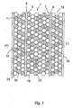
- a typical system of the present invention is shown in Figure 1 and is very similar to that of the prior art systems except for the selection of the resins in the various channels.
- a product channel 1 through which liquid to be processed can be flowed has at its first outer edge 3 an anion permeable membrane 5 which defines the outer limit of the product channel on that side.
- the opposite and second outer edge 7 of the product channel is defined by a cation permeable membrane 9.
- the two membranes, 5, 9 are spaced apart from each other to define the product channel 1.
- a first waste channel 11 is formed on the opposite side of the anionic membrane 5 and is formed between the anion permeable membrane 5 and the anode 12 that is spaced outwardly and apart from the anion membrane 5.
- the cation side waste channel 13 is formed between the cation permeable membrane 7 and the cathode 15.
- the product channel 1 is filled with a mixed bed of ion exchange materials.
- they are in the form of beads. These beads are either anion specific or cation specific.
- the anion beads 19 are Type I beads.
- the others are cation beads 21.
- beads are the most common form of ion exchange materials used, the present invention is not limited to the use of ion exchange materials, either cationic or anionic, in the form. of beads. They may also be in the form of irregular shaped particles, fibers, rods, fabrics or porous monoliths
- the liquid to be purified is flowed into the product channel 1 while an electrical potential is applied to the system.
- the beads 19, 21 in the product channel 1 selectively cause the ions in the liquid to attach to the bead surfaces where they are transferred from bead to bead toward the electrode (anode or cathode) they favor.
- the ion selective membrane either the anion or cation permeable membrane depending on their polarity, (5, 7) they are passed to beads in the form of mixed beds of anion beads 23 and cation beads 25 in the waste channels 11, 13.
- a liquid is also flowed through each waste channel 11,13 to remove the ions from the beads and carries them to waste.
- the anion ion exchange materials used in the present system are comprised of either only anion ion exchange materials having a low affinity for the specie or species desired to be retained or if desired, such materials in combination with Type I ion exchange materials.
- the ratio of Type I to "low affinity" anion ion exchange materials is from about 50 : 50 to about 1: 99.
- it is from about 40 : 60 to about 10 : 90, more preferably about 25 : 75 to about 20 : 80.
- low affinity anion ion exchange matenats it is meant to Include those anion materials that have a relatively low affinity for bicarbonate anion specie(s) to be retained and removed from the product channel.
- low affinity it is meant any anion selective ion exchange material which has an affinity for the bicarbonate anion specie(s) which is less than 5. Preferably, it would have an affinity of from about 1.01 to about 5, more preferably from about 1.01 to about 3.
- Low affinity anion ion exchange materials having a relatively low affinity for most anions, especially carbonate and bicarbonate include but are not limited anion ion exchange materials having weakly basic groups, anion ion exchange materials having Type II functional groups and mixtures thereof. Commercially, these ion exchange materials are available from Rohm & Haas of Philadelphia, Pennsylvania under the name of Amberlite 410.
- Type 1 ion exchange materials are available from Rohm & Haas of Philadelphia, Pennsylvania under the name of Amberlite 400.
- the cation ion exchange materials can be any ion exchange material commonly used in EDI modules to attract and transfer ions from the liquid to the waste channel.
- a preferred cation ion exchange materials is the Amberlite 200 series of ion exchange materials from Rohm & Haas of Philadelphia, Pennsylvania.
- Type 1 and low affinity anion ion exchange materials and cation ion exchange materials include E.I. Du Pont de Nemours, of Wilmington, Delaware, Dow Chemicals of Midland, Michigan and various Japanese companies.
- ion exchange capabilities of these materials may be inherent in the chemical structure of the materials used.
- they can be grafted, crosslinked or otherwise attached to the surfaces of the support material, be it in the form of beads, other particle shapes, fabrics, rods, fibers, monoliths, etc, as discussed above.
- the membranes used in the module may be any anion permeable or cation permeable membrane typically used in EDI modules. Such membranes are commercially available from Millipore Corporation of Bedford, Massachusetts under the CHEMPURE name. Similar membranes are available from Ionics, Inc of Watertown, Massachusetts and U.S. Filter Corporation of Lowell, Massachusetts.
- the anion membranes contain a low affinity anion exchange material to aid in the rapid transfer of the ions from the product channel to the waste channels. It has been determined that the use of anion membranes containing a low affinity ion exchange materials speeds the transfer of the anions across the membrane from the product channel to the waste channels and makes the transfer more complete than using an unfilled membrane or one which uses ion exchanges materials which have a high affinity to the ions that are trying to pass through the membrane toward their selected electrical potential. In particular, it has been found that the incorporation of the low affinity anion ion exchange materials described above is of particular use in reducing the barrier to anion transfer across the membranes.
- the low affinity anion ion exchange materials may be simply incorporated into the membrane during its manufacture as a filler. If desired, it may be reduced in size such as by grinding or chopping so as to incorporate more material into the membrane and to ensure the material is contained within the depth of the membrane thickness.
- the inclusion of the ion exchange materials in the manufacture of the membranes especially those formed by casting or melt extrusion methods. See U.S. Patents 5,531,899 and U.S. 4,203, 848 , the teachings of which are incorporated herein in their entities by reference, for examples of how such membranes are made.
- the method of making the module is well known and it may be done by assembling the various components together and clamping them in liquid tight fit between two end plates made of liquid impermeable material such as stainless steel or by using plastic components that are then sealed by heat or glue or other such means together into an integral, liquid tight assembly. See US Patents 4,632,745 , 4,747,929 , 4,753,681 , 4,925,541 , 4,931,160 , 4,956,071 , 5,116,509 , 5,154,809 and RE 35,741 , 5,211,823 , 5,259,936 , 5,681,438 and 5,593,563 .
- module may also be used. For example, one may use multiple product channels with their associated waste channels. Alternatively, one may make a half module using one product channel with one waste channel arranged to be closest to the electrode that attracts the ion to be removed. For example, one may simply make a half module that removes anions from the first stage of the EDI system. This may be followed with a series of one or more multi-channeled modules to form an EDI system.
- Two EDI modules according to Figure 1 were constructed. Both contained a mixed bed of Type 1 anion resin (Amberlite 400) and a cation resin (Amberlite 200). The first module contained the same mixed resin bed in each waste channel. The second module used a mixed bed of cation resin (Amberlite 400) and a low affinity anion resin (Amberlite 410).
- Example 1 The two modules of each type listed in Example 1 were then run continuously for one month and then intermittently, one hour off, two hours on for an additional seven months.
- Water was supplied first from a RO (reverse osmosis) feed using well water (St. Quentin, France) for four months, then from a RO feed from municipal water ( St. Quentin, France) for one month and then back to the RO feed based on well water (St. Quentin, France) with the water on average containing 1-4 ppm calcium and 25 to 35 ppm carbon dioxide. 100 milliamps current was applied to each module.
- RO reverse osmosis
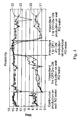
- Figure 3 shows the impedence of the modules over time with the two prior art modules 30 and 31 showing a markedly higher impedence than the two modules of the present invention 32 and 33.
- Figure 4 shows the resistivity of the water produced by the 4 modules over the time of the test. Again the modules of the present invention exhibited much purer and consistently purer water than the modules of the prior art.
Landscapes
- Chemical & Material Sciences (AREA)
- Chemical Kinetics & Catalysis (AREA)
- Engineering & Computer Science (AREA)
- Water Supply & Treatment (AREA)
- Life Sciences & Earth Sciences (AREA)
- Organic Chemistry (AREA)
- Health & Medical Sciences (AREA)
- Analytical Chemistry (AREA)
- Urology & Nephrology (AREA)
- Molecular Biology (AREA)
- Electrochemistry (AREA)
- General Chemical & Material Sciences (AREA)
- Hydrology & Water Resources (AREA)
- Environmental & Geological Engineering (AREA)
- Water Treatment By Electricity Or Magnetism (AREA)
- Separation Using Semi-Permeable Membranes (AREA)
Abstract
Claims (13)
- Système pour l'électrodésionisation de liquides comprenant une cathode (15), une anode (12) espacée de la cathode, un potentiel électrique appliqué entre la cathode et l'anode, une membrane (5) perméable aux anions espacée de l'anode et définissant un premier canal (11) de rebut entre la membrane perméable aux anions et l'anode, une membrane (9) perméable aux cations espacée de la cathode et définissant un second canal (13) de rebut entre la membrane perméable aux cations et la cathode, ladite membrane perméable aux anions et ladite membrane perméable aux cations étant adjacentes mais espacées l'une de l'autre de façon à définir un canal (1) de produit, ledit canal de produit contenant un lit mélangé de matières (19, 21) échangeuses d'ions, lesdites matières étant sélectives d'anions (19) et sélectives de cations (21), dans lequel lesdites matières (19) échangeuses d'ions sélectives d'anions sont des matières échangeuses d'anions de type I, lesdits premier et second canaux de rebut contenant un lit mélangé de matières (23, 25) échangeuses d'ions, lesdites matières comprenant des matières (25) sélectives de cations et des matières (23) sélectives d'anions, caractérisé en ce que les matières (23) sélectives d'anions dans les canaux de rebut sont choisies à partir du groupe constitué de matières anioniques ayant une affinité inférieure à 5 pour l'espèce (les espèces) anion bicarbonate devant être retenue(s) et éliminée(s) du canal de produit par comparaison aux ions hydroxyle, ou d'une combinaison de matières échangeuses d'anions du type I et de matières anioniques ayant une affinité inférieure à 5 pour l'espèce (les espèces) anion bicarbonate devant être retenue(s) et éliminée(s) du canal de produit par comparaison aux ions hydroxyle, dans un rapport allant de 50:50 à 1:99.
- Système selon la revendication 1, dans lequel la membrane perméable aux anions et la membrane perméable aux cations sont remplies avec des matières échangeuses d'ions.
- Système selon la revendication 1 ou 2, dans lequel la membrane perméable aux anions et la membrane perméable aux cations sont remplies avec des matières échangeuses d'ions, et la membrane perméable aux anions contient une matière anionique ayant une affinité inférieure à 5 pour l'espèce (les espèces) anion bicarbonate par comparaison aux ions hydroxyle.
- Système selon la revendication 3, dans lequel la matière anionique ayant une affinité inférieure à 5 est choisie à partir du groupe constitué des matières anioniques ayant des groupes faiblement basiques, des matières anioniques ayant des groupes fonctionnels du type II et de leurs mélanges.
- Système selon la revendication 1, dans lequel la matière échangeuse d'ions est sous une forme choisie à partir du groupe constitué de billes, de particules de forme irrégulière, de fibres, de bâtonnets, de tissus et de monolithes poreux.
- Système selon la revendication 5, dans lequel la matière échangeuse d'ions est sous la forme de billes.
- Module d'électrodésionisation (EDI pour "ElectroDeIonization") comprenant un système pour l'électrodésionisation de liquides selon l'une quelconque des revendications 1 à 3, le module d'EDI comprenant un ou plusieurs canaux de produit, un ou plusieurs canaux de rebut, deux électrodes formées d'une anode et d'une cathode et un lit mélangé de matières échangeuses d'ions dans les un ou plusieurs canaux de produit et les un ou plusieurs canaux de rebut, et dans lequel les matières anioniques ayant une affinité inférieure à 5 pour l'espèce (les espèces) anion bicarbonate par comparaison aux ions hydroxyle, sont choisies à partir du groupe constitué des matières anioniques ayant des groupes faiblement basiques, des matières anioniques ayant des groupes fonctionnels du type II et de leurs mélanges.
- Module selon la revendication 7, dans lequel il y a un canal de rebut et un canal de produit et ledit canal de rebut est disposé le plus près de l'électrode qui attire l'ion à éliminer.
- Module selon la revendication 8, dans lequel il y a un canal de rebut et un canal de produit et ledit canal de rebut est disposé le plus près de l'anode.
- Module selon la revendication 8, dans lequel il y a un canal de rebut et un canal de produit et ledit canal de rebut est disposé le plus près de la cathode.
- Module selon la revendication 7, dans lequel il y a deux ou plus de deux canaux de rebut et deux ou plus de deux canaux de produit.
- Module selon l'une quelconque des revendications 7 à 11, dans lequel la matière échangeuse d'ions est sous une forme choisie à partir du groupe constitué de billes, de particules de forme irrégulière, de fibres, de bâtonnets, de tissus et de monolithes poreux.
- Module selon la revendication 11, dans lequel la matière échangeuse d'ions est sous la forme de billes.
Applications Claiming Priority (3)
| Application Number | Priority Date | Filing Date | Title |
|---|---|---|---|
| US20255500P | 2000-05-10 | 2000-05-10 | |
| US202555P | 2000-05-10 | ||
| PCT/US2001/009582 WO2001085313A2 (fr) | 2000-05-10 | 2001-03-26 | Module d'electrodesionisation ameliore |
Publications (2)
| Publication Number | Publication Date |
|---|---|
| EP1282463A2 EP1282463A2 (fr) | 2003-02-12 |
| EP1282463B1 true EP1282463B1 (fr) | 2010-10-27 |
Family
ID=22750360
Family Applications (1)
| Application Number | Title | Priority Date | Filing Date |
|---|---|---|---|
| EP01926430A Expired - Lifetime EP1282463B1 (fr) | 2000-05-10 | 2001-03-26 | Module d'electrodesionisation ameliore |
Country Status (5)
| Country | Link |
|---|---|
| US (1) | US6596145B2 (fr) |
| EP (1) | EP1282463B1 (fr) |
| JP (1) | JP3895180B2 (fr) |
| DE (1) | DE60143351D1 (fr) |
| WO (1) | WO2001085313A2 (fr) |
Cited By (1)
| Publication number | Priority date | Publication date | Assignee | Title |
|---|---|---|---|---|
| WO2014032751A1 (fr) | 2012-08-27 | 2014-03-06 | Merck Patent Gmbh | Module et appareil d'électro-désionisation améliorés |
Families Citing this family (14)
| Publication number | Priority date | Publication date | Assignee | Title |
|---|---|---|---|---|
| EP1308201B1 (fr) * | 2001-10-31 | 2005-01-05 | Kurita Water Industries Ltd. | Appareil de desionisation electrique |
| US7501061B2 (en) | 2002-10-23 | 2009-03-10 | Siemens Water Technologies Holding Corp. | Production of water for injection using reverse osmosis |
| JP4363587B2 (ja) * | 2003-06-09 | 2009-11-11 | オルガノ株式会社 | 電気式脱イオン水製造装置の運転方法及び電気式脱イオン水製造装置 |
| US7892848B2 (en) * | 2005-04-14 | 2011-02-22 | Trovion Singapore Pte. Ltd., Co. | Method of ion chromatography wherein a specialized electrodeionization apparatus is used |
| US20060231403A1 (en) * | 2005-04-14 | 2006-10-19 | Riviello John M | Chambered electrodeionization apparatus with uniform current density, and method of use |
| US8529759B2 (en) | 2005-07-20 | 2013-09-10 | Organo Corporation | Electric deionized water production apparatus |
| JP2009505821A (ja) * | 2005-08-26 | 2009-02-12 | インテグリス・インコーポレーテッド | 交換樹脂を含有する多孔性膜 |
| MX2008016077A (es) * | 2006-06-22 | 2009-01-19 | Siemens Water Tech Corp | Tratamiento de agua con bajo potencial de incrustacion. |
| US20080067069A1 (en) * | 2006-06-22 | 2008-03-20 | Siemens Water Technologies Corp. | Low scale potential water treatment |
| WO2008048656A2 (fr) | 2006-10-18 | 2008-04-24 | Kinetico Incorporated | Appareil d'électrorégénération et procédé de traitement d'eau |
| MX2010005876A (es) | 2007-11-30 | 2010-06-15 | Siemens Water Tech Corp | Sistemas y metodos para tratamiento de agua. |
| US9724645B2 (en) | 2012-02-02 | 2017-08-08 | Tangent Company Llc | Electrochemically regenerated water deionization |
| GB201216526D0 (en) * | 2012-09-17 | 2012-10-31 | Vws Uk Ltd | Water treatment method and apparatus |
| US10384919B2 (en) * | 2014-11-25 | 2019-08-20 | Troy L. Deal | Mobile bottling, packaging and distribution system |
Family Cites Families (26)
| Publication number | Priority date | Publication date | Assignee | Title |
|---|---|---|---|---|
| GB776469A (en) * | 1953-12-17 | 1957-06-05 | Tno | Process and apparatus for the electrolytic deionisation of salt-containing liquids |
| GB1050960A (fr) * | 1964-11-25 | |||
| JPS5850155B2 (ja) * | 1976-08-05 | 1983-11-09 | 旭化成株式会社 | 改良された廃液処理法 |
| US4203848A (en) | 1977-05-25 | 1980-05-20 | Millipore Corporation | Processes of making a porous membrane material from polyvinylidene fluoride, and products |
| USRE35741E (en) | 1984-07-09 | 1998-03-10 | Millipore Corporation | Process for purifying water |
| US4925541B1 (en) | 1984-07-09 | 1994-08-02 | Millipore Corp | Electrodeionization apparatus and method |
| US4956071A (en) * | 1984-07-09 | 1990-09-11 | Millipore Corporation | Electrodeionization apparatus and module |
| US4931160A (en) | 1987-05-11 | 1990-06-05 | Millipore Corporation | Electrodeionization method and apparatus |
| EP0170895B1 (fr) | 1984-07-09 | 1989-03-22 | Millipore Corporation | Appareil et procédé d'électrodésionisation |
| US5154809A (en) | 1984-07-09 | 1992-10-13 | Millipore Corporation | Process for purifying water |
| US4753681A (en) | 1986-09-30 | 1988-06-28 | Millipore Corporation | Method for defouling electrodeionization apparatus |
| US4747929A (en) | 1986-10-01 | 1988-05-31 | Millipore Corporation | Depletion compartment and spacer construction for electrodeionization apparatus |
| JPH0759296B2 (ja) * | 1988-07-27 | 1995-06-28 | 栗田工業株式会社 | 純水製造装置 |
| US5026465A (en) * | 1989-08-03 | 1991-06-25 | Ionics, Incorporated | Electrodeionization polarity reversal apparatus and process |
| US5116509A (en) | 1989-09-08 | 1992-05-26 | Millipore Corporation | Electrodeionization and ultraviolet light treatment method for purifying water |
| JP3009221B2 (ja) * | 1990-12-17 | 2000-02-14 | ユー・エス・フィルター/アイオンピュア・インコーポレーテッド | 電気脱イオン化装置 |
| US5211823A (en) | 1991-06-19 | 1993-05-18 | Millipore Corporation | Process for purifying resins utilizing bipolar interface |
| US5259936A (en) | 1991-06-19 | 1993-11-09 | Millipore Corporation | Purified ion exchange resins and process |
| JP3188511B2 (ja) * | 1992-03-30 | 2001-07-16 | 野村マイクロ・サイエンス株式会社 | 電気透析装置 |
| JPH08182991A (ja) * | 1994-12-28 | 1996-07-16 | Asahi Glass Co Ltd | 脱イオン水製造装置 |
| US5531899A (en) | 1995-06-06 | 1996-07-02 | Millipore Investment Holdings Limited | Ion exchange polyethylene membrane and process |
| JPH09271781A (ja) * | 1996-04-08 | 1997-10-21 | Toshiba Corp | 廃水からの窒素分除去方法 |
| US5593563A (en) | 1996-04-26 | 1997-01-14 | Millipore Corporation | Electrodeionization process for purifying a liquid |
| US5681438A (en) | 1996-05-31 | 1997-10-28 | Millipore Corporation | Membrane module assembly |
| US5868915A (en) * | 1996-09-23 | 1999-02-09 | United States Filter Corporation | Electrodeionization apparatus and method |
| JPH10277557A (ja) * | 1997-04-10 | 1998-10-20 | Asahi Glass Co Ltd | 脱イオン水製造装置 |
-
2001
- 2001-03-26 WO PCT/US2001/009582 patent/WO2001085313A2/fr not_active Ceased
- 2001-03-26 EP EP01926430A patent/EP1282463B1/fr not_active Expired - Lifetime
- 2001-03-26 JP JP2001581963A patent/JP3895180B2/ja not_active Expired - Lifetime
- 2001-03-26 DE DE60143351T patent/DE60143351D1/de not_active Expired - Lifetime
- 2001-04-02 US US09/824,275 patent/US6596145B2/en not_active Expired - Lifetime
Cited By (2)
| Publication number | Priority date | Publication date | Assignee | Title |
|---|---|---|---|---|
| WO2014032751A1 (fr) | 2012-08-27 | 2014-03-06 | Merck Patent Gmbh | Module et appareil d'électro-désionisation améliorés |
| US9550687B2 (en) | 2012-08-27 | 2017-01-24 | Merck Patent Gmbh | Electrodeionization module and apparatus |
Also Published As
| Publication number | Publication date |
|---|---|
| JP3895180B2 (ja) | 2007-03-22 |
| DE60143351D1 (de) | 2010-12-09 |
| US6596145B2 (en) | 2003-07-22 |
| WO2001085313A2 (fr) | 2001-11-15 |
| US20020139676A1 (en) | 2002-10-03 |
| WO2001085313A3 (fr) | 2002-02-07 |
| EP1282463A2 (fr) | 2003-02-12 |
| JP2003532520A (ja) | 2003-11-05 |
Similar Documents
| Publication | Publication Date | Title |
|---|---|---|
| US6596145B2 (en) | Electrodeionization module | |
| CA2358935C (fr) | Procede et dispositif d'electro-deionisation | |
| EP0892677B1 (fr) | Procede et dispositif d'electrodeionisation | |
| EP2029262B1 (fr) | Procédé et appareil de déplacement de la distribution du courant dans des systèmes d'électrodéionisation. | |
| US6482304B1 (en) | Apparatus and method of recirculating electrodeionization | |
| US6607647B2 (en) | Electrodeionization apparatus with expanded conductive mesh electrode and method | |
| US5858191A (en) | Electrodeionization apparatus and method | |
| US5211823A (en) | Process for purifying resins utilizing bipolar interface | |
| EP1034833B1 (fr) | Compartiments pour appareil d'électrodésionisation | |
| EP1553056B1 (fr) | Deioniseur electrique | |
| AU2007297499B2 (en) | Arrangement of ion exchange material within an electrodeionization apparatus | |
| US20040060823A1 (en) | Device and method for eletrodialysis | |
| JP2001239270A (ja) | 電気式脱イオン水製造装置及び脱イオン水製造方法 | |
| EP1651331B1 (fr) | Module d'electrodesionisation et appareil le comportant | |
| CA2503733C (fr) | Appareil d'electrodeionisation | |
| JP5015990B2 (ja) | 電気式脱イオン水製造装置 | |
| JP3721883B2 (ja) | 電気脱イオン装置 | |
| KR102436864B1 (ko) | 전기식 탈이온수 제조장치 | |
| JP4819026B2 (ja) | 電気式脱イオン水製造装置および脱イオン水製造方法 | |
| JP4819020B2 (ja) | スパイラル型電気式脱イオン水製造装置 | |
| JPH11104652A (ja) | 電気式脱イオン水製造装置 | |
| KR20250155590A (ko) | 전기식 탈이온수 제조 장치 및 그것을 사용한 순수 제조 방법 |
Legal Events
| Date | Code | Title | Description |
|---|---|---|---|
| PUAI | Public reference made under article 153(3) epc to a published international application that has entered the european phase |
Free format text: ORIGINAL CODE: 0009012 |
|
| 17P | Request for examination filed |
Effective date: 20020808 |
|
| AK | Designated contracting states |
Designated state(s): DE FR GB IT |
|
| RAP1 | Party data changed (applicant data changed or rights of an application transferred) |
Owner name: MILLIPORE CORPORATION |
|
| 17Q | First examination report despatched |
Effective date: 20070629 |
|
| GRAP | Despatch of communication of intention to grant a patent |
Free format text: ORIGINAL CODE: EPIDOSNIGR1 |
|
| GRAS | Grant fee paid |
Free format text: ORIGINAL CODE: EPIDOSNIGR3 |
|
| GRAA | (expected) grant |
Free format text: ORIGINAL CODE: 0009210 |
|
| AK | Designated contracting states |
Kind code of ref document: B1 Designated state(s): DE FR GB IT |
|
| REG | Reference to a national code |
Ref country code: GB Ref legal event code: FG4D |
|
| REF | Corresponds to: |
Ref document number: 60143351 Country of ref document: DE Date of ref document: 20101209 Kind code of ref document: P |
|
| PLBE | No opposition filed within time limit |
Free format text: ORIGINAL CODE: 0009261 |
|
| STAA | Information on the status of an ep patent application or granted ep patent |
Free format text: STATUS: NO OPPOSITION FILED WITHIN TIME LIMIT |
|
| 26N | No opposition filed |
Effective date: 20110728 |
|
| REG | Reference to a national code |
Ref country code: DE Ref legal event code: R097 Ref document number: 60143351 Country of ref document: DE Effective date: 20110728 |
|
| REG | Reference to a national code |
Ref country code: DE Ref legal event code: R082 Ref document number: 60143351 Country of ref document: DE Representative=s name: HENKEL, BREUER & PARTNER, DE |
|
| REG | Reference to a national code |
Ref country code: DE Ref legal event code: R082 Ref document number: 60143351 Country of ref document: DE Representative=s name: PATENTANWAELTE HENKEL, BREUER & PARTNER, DE Effective date: 20120613 Ref country code: DE Ref legal event code: R081 Ref document number: 60143351 Country of ref document: DE Owner name: EMD MILLIPORE CORPORATION, US Free format text: FORMER OWNER: MILLIPORE CORP., BILLERICA, US Effective date: 20120613 Ref country code: DE Ref legal event code: R081 Ref document number: 60143351 Country of ref document: DE Owner name: EMD MILLIPORE CORPORATION, BILLERICA, US Free format text: FORMER OWNER: MILLIPORE CORP., BILLERICA, MASS., US Effective date: 20120613 Ref country code: DE Ref legal event code: R082 Ref document number: 60143351 Country of ref document: DE Representative=s name: PATENTANWAELTE HENKEL, BREUER & PARTNER MBB, DE Effective date: 20120613 |
|
| REG | Reference to a national code |
Ref country code: FR Ref legal event code: PLFP Year of fee payment: 16 |
|
| REG | Reference to a national code |
Ref country code: FR Ref legal event code: PLFP Year of fee payment: 17 |
|
| REG | Reference to a national code |
Ref country code: FR Ref legal event code: PLFP Year of fee payment: 18 |
|
| PGFP | Annual fee paid to national office [announced via postgrant information from national office to epo] |
Ref country code: GB Payment date: 20200318 Year of fee payment: 20 Ref country code: DE Payment date: 20200310 Year of fee payment: 20 Ref country code: IT Payment date: 20200221 Year of fee payment: 20 |
|
| PGFP | Annual fee paid to national office [announced via postgrant information from national office to epo] |
Ref country code: FR Payment date: 20200214 Year of fee payment: 20 |
|
| REG | Reference to a national code |
Ref country code: DE Ref legal event code: R071 Ref document number: 60143351 Country of ref document: DE |
|
| REG | Reference to a national code |
Ref country code: GB Ref legal event code: PE20 Expiry date: 20210325 |
|
| PG25 | Lapsed in a contracting state [announced via postgrant information from national office to epo] |
Ref country code: GB Free format text: LAPSE BECAUSE OF EXPIRATION OF PROTECTION Effective date: 20210325 |