EP1282483B1 - Greifer für ein schlaggerät - Google Patents
Greifer für ein schlaggerät Download PDFInfo
- Publication number
- EP1282483B1 EP1282483B1 EP01936512A EP01936512A EP1282483B1 EP 1282483 B1 EP1282483 B1 EP 1282483B1 EP 01936512 A EP01936512 A EP 01936512A EP 01936512 A EP01936512 A EP 01936512A EP 1282483 B1 EP1282483 B1 EP 1282483B1
- Authority
- EP
- European Patent Office
- Prior art keywords
- handles
- handle
- trigger
- tool
- acting
- Prior art date
- Legal status (The legal status is an assumption and is not a legal conclusion. Google has not performed a legal analysis and makes no representation as to the accuracy of the status listed.)
- Expired - Lifetime
Links
- 230000001681 protective effect Effects 0.000 claims abstract description 16
- 230000000007 visual effect Effects 0.000 claims description 3
- 238000009527 percussion Methods 0.000 description 9
- 230000010355 oscillation Effects 0.000 description 3
- 208000027418 Wounds and injury Diseases 0.000 description 1
- 230000000295 complement effect Effects 0.000 description 1
- 230000006378 damage Effects 0.000 description 1
- 238000006073 displacement reaction Methods 0.000 description 1
- 238000002347 injection Methods 0.000 description 1
- 239000007924 injection Substances 0.000 description 1
- 208000014674 injury Diseases 0.000 description 1
- 230000010354 integration Effects 0.000 description 1
- 239000000463 material Substances 0.000 description 1
- 238000000465 moulding Methods 0.000 description 1
- 239000000243 solution Substances 0.000 description 1
Images



Classifications
-
- B—PERFORMING OPERATIONS; TRANSPORTING
- B25—HAND TOOLS; PORTABLE POWER-DRIVEN TOOLS; MANIPULATORS
- B25F—COMBINATION OR MULTI-PURPOSE TOOLS NOT OTHERWISE PROVIDED FOR; DETAILS OR COMPONENTS OF PORTABLE POWER-DRIVEN TOOLS NOT PARTICULARLY RELATED TO THE OPERATIONS PERFORMED AND NOT OTHERWISE PROVIDED FOR
- B25F5/00—Details or components of portable power-driven tools not particularly related to the operations performed and not otherwise provided for
- B25F5/02—Construction of casings, bodies or handles
-
- B—PERFORMING OPERATIONS; TRANSPORTING
- B25—HAND TOOLS; PORTABLE POWER-DRIVEN TOOLS; MANIPULATORS
- B25D—PERCUSSIVE TOOLS
- B25D17/00—Details of, or accessories for, portable power-driven percussive tools
- B25D17/04—Handles; Handle mountings
Definitions
- the invention relates to the technical sector of hammer-type percussion, concrete breaker, perforator, working with any source of energy, especially compressed air.
- this type of apparatus has handles of gripping of which at least one is subject to a trigger conformed to act on a device subject to the source of energy that has a part of the body of the device.
- the handles In an attempt to reduce the significant vibrations resulting from the operation of these percussion apparatus, it has been proposed to suspend the handles relative to the body of the apparatus, that is to say to mount them in an oscillating manner with the ability to angular displacement in the same plane as that defined in the body of the device.
- the handles are mounted in lateral overflow of the body of the apparatus, in an opposite manner, being substantially aligned.
- the trigger is carried by one of the handles with which it oscillates so, while the switch to operate for the required power distribution, is integral with the body of the device.
- the trigger is located above the corresponding grip handle, hence the need to provide a means of locking in order to avoid any inadvertent triggering given the trigger position of the command that is not protected.
- This obligation to use a means of Intermediate trigger lock generates an increase in weight not insignificant and increases the number of parts needed for the correct operation.
- the aim of the invention is to remedy these drawbacks, simple, safe, effective and rational way.
- the problem that the invention proposes to solve is to suppress this intermediate piece of locking avoiding any trigger inadvertent trigger trigger while aiming, to ensure the protection of the user's hands. Indeed, it appears, according to state of the art, that the user's hands are not protected, this which can be important, considering the difficult conditions in which are sometimes used these percussion devices, the hands of the user can be directly exposed with risk of injury.
- each protective element constitutes a sleeve having a chambering internal shape and section corresponding to those of the handle of gripping.
- the part of the profiled shape on the side of the body of the apparatus serves as a housing adapted to partially grip the section of said body, said housing having a slot for engagement, overflow and maneuvering the trigger switch, under the handle grasping.
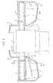
- FIG. 1 illustrates a non-limiting example of a device of vibration in the form of a breaker hammer.
- This device includes a body (1) surmounted by a rigid head (2).
- the head (2) is equipped, in lateral overflow, two opposite handles (3) mounted with capacity oscillation.
- the head receives a control trigger (4) adapted to trigger at will a power source controlled or not a tool of percussion (not shown).
- each handle (3) presents, directly or in a reported way, protective elements (5) delimiting a closed space (E).
- This closed space (E) has the function, on the one hand, to allow the passage and wrapping of the hands of the user in the gripping position of the handles and, on the other hand, the overflow of the control trigger (4).
- the protective element (5) comprises a body (5a) capable of wrapping, in whole or in part, the section of the corresponding handle (3).
- the body (5a) constitutes a sheath having an internal chamber (5a1) of shape and section complementary to those of the handle (3).
- the ends of the body (5a) are joined by a shaped shape (5b) delimiting the space (E) as an under guard.
- Part (5b1) of the shaped form (5b) located on the side of the body of the apparatus, in particular the head (2) serves as a housing adapted to partially enclose the section of the head (2).
- the chambering (5a1) of the body (5a) opens at this part (5b1) to allow the introduction of the handles (3).
- the housing (5b1) has a slot (5c) for engagement, overflow and operation of the control trigger (4).
- the slot (5c) is established under the recess (5a1) so that the trigger (3) is located under the handle, that is to say under the body (5a), to inside the protection space (E).
- the entire protective element (5) as defined is advantageously produced by injection of a plastic material. Note that the opposite of the part (5b1) of the profiled form (5b) acting as an under guard, the portion (5b2) at the body (5a) is full. Also note that the shapes of the profiled part (5b) serving as the sub-guard are carefully determined so as not to alter the oscillation of the handles grasping. This is particularly the case with the connection of the lower part of the part (5b3) of the sub-guard with the part (5b1) acting as a crankcase.
- the gripping system as defined according to the characteristics of the invention can also be completed by a connecting element (7) sectional section for covering the upper part of the head (2) and ensuring a visual connection between two protective elements (5) in particular between the two parts (5b1) acting as crankcase.
- This connecting element (7) can be independent and reported to be fixed by any known means and suitable for the head (2).
- connection element (7) is rendered solidary, with articulation capacity, of each of the protective elements (5) in particular at the crankcase portion (5b1), to constitute a unitary whole.
- the articulated connection between the connecting element (7) and each of the protection elements (5) can be obtained by any means known at the time of molding the whole of the gripping system.
- the trigger of control can be mounted under one of the gripping handles avoiding thus the use of an intermediate locking part.
- the trigger is perfectly protected in the defined space. It is the same with regards the hands of the user.
Landscapes
- Engineering & Computer Science (AREA)
- Mechanical Engineering (AREA)
- Percussive Tools And Related Accessories (AREA)
- Advancing Webs (AREA)
- Walking Sticks, Umbrellas, And Fans (AREA)
- Details Of Rigid Or Semi-Rigid Containers (AREA)
- Steering Devices For Bicycles And Motorcycles (AREA)
- Manipulator (AREA)
Claims (6)
- Greifer für ein Schlaggerät, insbesondere mit Griffen (3), die gegenüber dem Rumpf (1) des Schlaggerätes gelenkig montiert sind, wobei einer der Griffe (3) mit einem Steuerhebel (4) ausgestattet ist, der auf eine Energiequelle wirkt, dadurch gekennzeichnet, dass jeder Griff (3) direkt oder aufgesetzt ein Schutzelement (5) mit einem Hauptteil (5a) besitzt, das den Abschnitt des entsprechenden Griffes (3) ganz oder teilweise umgeben kann, wobei die Enden des Hauptteils (5a) durch eine profilierte Form (5b) verbunden sind, die einen geschlossenen Raum (E) begrenzt, indem sie als Kontrolle dienen, und zwar einerseits für den Durchgang und das Umfassen der Hand des Benutzers in Griffposition der Griffe, und andererseits für das Vorstehen oder Herausragen und die Betätigung des Steuerhebels unter dem Griff in dem Raum (E).
- Greifer nach Anspruch 1, dadurch gekennzeichnet, dass der Hauptteil (5a) jedes Schutzelementes (5) eine Hülse darstellt, die innen eine allseitige Einschließung (5a1) besitzt, deren Form und Querschnitt dem des Griffes (3) entspricht.
- Greifer nach Anspruch 1, dadurch gekennzeichnet, dass der Teil der profilierten Form, der sich neben dem Rumpf (1) des Schlaggerätes befindet, als Gehäuse dient, das den Querschnitt des Rumpfes teilweise einklemmen kann, wobei das Gehäuse einen Spalt (5c) für den Eingriff, das Herausragen und die Betätigung des Steuerhebels unter dem Griff (3) besitzt.
- Greifer nach einem der Ansprüche 1 bis 3, wobei das Schlaggerät zwei einander gegenüberliegende Griffe (3) besitzt, die zu beiden Seiten eines Kopfes (2), der das Oberteil des Rumpfes (1) des Schlaggerätes darstellt, gelenkig angebracht sind, dadurch gekennzeichnet, dass der Kopf (2) von einem Element (7) bedeckt wird, das die visuelle Verbindung zwischen den beiden Teilen (5b) gewährleistet die als Gehäuse dienen.
- Greifer nach Anspruch 4, dadurch gekennzeichnet, dass das Verbindungselement (7) unabhängig und aufgesetzt ist, so dass es im Bereich des Kopfes (2) befestigt werden kann.
- Greifer nach Anspruch 4, dadurch gekennzeichnet, dass das Verbindungselement (7) mit den Schutzelementen (5), insbesondere mit dem Teil, das als Gehäuse dient (5b) gelenkig verbunden ist, so dass es eine Einheit bildet.
Applications Claiming Priority (3)
| Application Number | Priority Date | Filing Date | Title |
|---|---|---|---|
| FR0006318 | 2000-05-15 | ||
| FR0006318A FR2808719B1 (fr) | 2000-05-15 | 2000-05-15 | Systeme de prehension d'un appareil de percussion notamment |
| PCT/FR2001/001462 WO2001087546A1 (fr) | 2000-05-15 | 2001-05-15 | Systeme de prehension d'un appareil de percussion |
Publications (2)
| Publication Number | Publication Date |
|---|---|
| EP1282483A1 EP1282483A1 (de) | 2003-02-12 |
| EP1282483B1 true EP1282483B1 (de) | 2004-09-01 |
Family
ID=8850337
Family Applications (1)
| Application Number | Title | Priority Date | Filing Date |
|---|---|---|---|
| EP01936512A Expired - Lifetime EP1282483B1 (de) | 2000-05-15 | 2001-05-15 | Greifer für ein schlaggerät |
Country Status (6)
| Country | Link |
|---|---|
| EP (1) | EP1282483B1 (de) |
| AT (1) | ATE275026T1 (de) |
| AU (1) | AU2001262404A1 (de) |
| DE (1) | DE60105287T2 (de) |
| FR (1) | FR2808719B1 (de) |
| WO (1) | WO2001087546A1 (de) |
Families Citing this family (2)
| Publication number | Priority date | Publication date | Assignee | Title |
|---|---|---|---|---|
| FR2927010B1 (fr) | 2008-01-31 | 2010-06-11 | Sullair Europ | Dispositif de marteau piqueur a air comprime |
| CN117817628A (zh) * | 2022-02-08 | 2024-04-05 | 马鸣 | 一种风镐 |
Family Cites Families (5)
| Publication number | Priority date | Publication date | Assignee | Title |
|---|---|---|---|---|
| GB175866A (en) * | 1921-01-11 | 1922-03-02 | Alexander George Slade | Improvements in or relating to pneumatically operated percussive tools such as rivetting hammers and similarly operated implements |
| FR689169A (fr) * | 1930-01-31 | 1930-09-03 | Meudon Forges Atel | Perfectionnements aux marteaux piqueurs à air comprimé |
| GB2098121B (en) * | 1981-05-07 | 1984-09-26 | Mo Vysshee Teknicheskoe Uchili | Shock absorbing pneumatic percussive tool |
| EP0391856A3 (de) * | 1989-04-07 | 1992-07-08 | SIG Schweizerische Industrie-Gesellschaft | Pneumatischer Hammer |
| US5269045A (en) * | 1991-02-01 | 1993-12-14 | Ingersoll-Rand Company | Ergonomically adjustable tool handle |
-
2000
- 2000-05-15 FR FR0006318A patent/FR2808719B1/fr not_active Expired - Fee Related
-
2001
- 2001-05-15 AU AU2001262404A patent/AU2001262404A1/en not_active Abandoned
- 2001-05-15 EP EP01936512A patent/EP1282483B1/de not_active Expired - Lifetime
- 2001-05-15 DE DE60105287T patent/DE60105287T2/de not_active Expired - Lifetime
- 2001-05-15 AT AT01936512T patent/ATE275026T1/de not_active IP Right Cessation
- 2001-05-15 WO PCT/FR2001/001462 patent/WO2001087546A1/fr not_active Ceased
Also Published As
| Publication number | Publication date |
|---|---|
| EP1282483A1 (de) | 2003-02-12 |
| FR2808719A1 (fr) | 2001-11-16 |
| AU2001262404A1 (en) | 2001-11-26 |
| DE60105287T2 (de) | 2005-09-15 |
| FR2808719B1 (fr) | 2002-09-20 |
| WO2001087546A1 (fr) | 2001-11-22 |
| DE60105287D1 (de) | 2004-10-07 |
| ATE275026T1 (de) | 2004-09-15 |
Similar Documents
| Publication | Publication Date | Title |
|---|---|---|
| EP0044797B1 (de) | Einstülpbare Ausgiesstülle mit Garantieanordnung | |
| EP0809458B1 (de) | Elektrisch betriebener handschläger und -rührer | |
| FR2721546A1 (fr) | Dispositif à poignées pour une scie à moteur à chaîne. | |
| EP1251966B1 (de) | Abgabevorrichtung mit greifereinrichtung | |
| FR2848138A1 (fr) | Couteau | |
| EP0942674A1 (de) | Haushaltsgerät mit rotierendem messer zur zubereitung von lebensmitteln versehen mit sicherheitsvorrichtung | |
| WO2000078195A1 (fr) | Batteur-mixeur electrique a main comportant un dispositif de securite | |
| FR2485684A1 (fr) | Levier de commande manuelle a dispositif de securite | |
| EP1432865A1 (de) | Hinten offenes bügeleisen | |
| FR2507947A1 (fr) | Rasoir muni d'un couvercle de lame actionnable par levier | |
| CH665379A5 (fr) | Necessaire de rasage. | |
| FR2808719A1 (fr) | Systeme de prehension d'un appareil de percussion notamment | |
| FR2534977A1 (fr) | Injecteur de carburant | |
| FR2616833A1 (fr) | Dispositif de commande manuelle d'ouverture de porte de vehicule | |
| CA1260285A (fr) | Dispositif de fermeture de bagage | |
| FR2484067A1 (fr) | Pince munie d'une garniture absorbante amovible pour le sechage des manches de raquettes de tennis et autres | |
| EP0251844B1 (de) | Klappgriff für eine Tür | |
| CH717488A2 (fr) | Couronne débrayable pour un dispositif antichoc. | |
| FR2720607A1 (fr) | Dispositif de retenue d'un accessoire sur un casque et casque équipé du dispositif. | |
| EP1205826A1 (de) | Einstellvorrichtung für eine Uhr vom angeschraubten Krone Typ | |
| FR2809654A1 (fr) | Dispositif de blocage et deblocage de lame sur couteau pliant a pompe | |
| EP0266253B1 (de) | Gasdruckreduzierventil mit kippender Membrane | |
| EP1818459B1 (de) | Vorrichtung zum Verschließen eines Rahmens mit Hilfe einer elastisch am Rahmen verschließbaren Abdeckung | |
| WO1995001933A1 (fr) | Dispositif pour l'ouverture d'une bouteille a capsule a couronne | |
| FR2894610A1 (fr) | Dispositif d'ouverture et de fermeture d'un vantail de porte de type va-et-vient |
Legal Events
| Date | Code | Title | Description |
|---|---|---|---|
| PUAI | Public reference made under article 153(3) epc to a published international application that has entered the european phase |
Free format text: ORIGINAL CODE: 0009012 |
|
| 17P | Request for examination filed |
Effective date: 20021118 |
|
| AK | Designated contracting states |
Designated state(s): AT BE CH CY DE DK ES FI FR GB GR IE IT LI LU MC NL PT SE TR |
|
| AX | Request for extension of the european patent |
Extension state: AL LT LV MK RO SI |
|
| GRAP | Despatch of communication of intention to grant a patent |
Free format text: ORIGINAL CODE: EPIDOSNIGR1 |
|
| GRAS | Grant fee paid |
Free format text: ORIGINAL CODE: EPIDOSNIGR3 |
|
| GRAA | (expected) grant |
Free format text: ORIGINAL CODE: 0009210 |
|
| AK | Designated contracting states |
Kind code of ref document: B1 Designated state(s): AT BE CH CY DE DK ES FI FR GB GR IE IT LI LU MC NL PT SE TR |
|
| PG25 | Lapsed in a contracting state [announced via postgrant information from national office to epo] |
Ref country code: NL Free format text: LAPSE BECAUSE OF FAILURE TO SUBMIT A TRANSLATION OF THE DESCRIPTION OR TO PAY THE FEE WITHIN THE PRESCRIBED TIME-LIMIT Effective date: 20040901 Ref country code: FI Free format text: LAPSE BECAUSE OF FAILURE TO SUBMIT A TRANSLATION OF THE DESCRIPTION OR TO PAY THE FEE WITHIN THE PRESCRIBED TIME-LIMIT Effective date: 20040901 Ref country code: TR Free format text: LAPSE BECAUSE OF FAILURE TO SUBMIT A TRANSLATION OF THE DESCRIPTION OR TO PAY THE FEE WITHIN THE PRESCRIBED TIME-LIMIT Effective date: 20040901 Ref country code: IE Free format text: LAPSE BECAUSE OF FAILURE TO SUBMIT A TRANSLATION OF THE DESCRIPTION OR TO PAY THE FEE WITHIN THE PRESCRIBED TIME-LIMIT Effective date: 20040901 Ref country code: AT Free format text: LAPSE BECAUSE OF FAILURE TO SUBMIT A TRANSLATION OF THE DESCRIPTION OR TO PAY THE FEE WITHIN THE PRESCRIBED TIME-LIMIT Effective date: 20040901 |
|
| REG | Reference to a national code |
Ref country code: GB Ref legal event code: FG4D Free format text: NOT ENGLISH |
|
| REG | Reference to a national code |
Ref country code: CH Ref legal event code: EP |
|
| REG | Reference to a national code |
Ref country code: IE Ref legal event code: FG4D Free format text: FRENCH |
|
| REF | Corresponds to: |
Ref document number: 60105287 Country of ref document: DE Date of ref document: 20041007 Kind code of ref document: P |
|
| PG25 | Lapsed in a contracting state [announced via postgrant information from national office to epo] |
Ref country code: DK Free format text: LAPSE BECAUSE OF FAILURE TO SUBMIT A TRANSLATION OF THE DESCRIPTION OR TO PAY THE FEE WITHIN THE PRESCRIBED TIME-LIMIT Effective date: 20041201 Ref country code: GR Free format text: LAPSE BECAUSE OF FAILURE TO SUBMIT A TRANSLATION OF THE DESCRIPTION OR TO PAY THE FEE WITHIN THE PRESCRIBED TIME-LIMIT Effective date: 20041201 Ref country code: SE Free format text: LAPSE BECAUSE OF FAILURE TO SUBMIT A TRANSLATION OF THE DESCRIPTION OR TO PAY THE FEE WITHIN THE PRESCRIBED TIME-LIMIT Effective date: 20041201 |
|
| PG25 | Lapsed in a contracting state [announced via postgrant information from national office to epo] |
Ref country code: ES Free format text: LAPSE BECAUSE OF FAILURE TO SUBMIT A TRANSLATION OF THE DESCRIPTION OR TO PAY THE FEE WITHIN THE PRESCRIBED TIME-LIMIT Effective date: 20041212 |
|
| GBT | Gb: translation of ep patent filed (gb section 77(6)(a)/1977) |
Effective date: 20050124 |
|
| LTIE | Lt: invalidation of european patent or patent extension |
Effective date: 20040901 |
|
| NLV1 | Nl: lapsed or annulled due to failure to fulfill the requirements of art. 29p and 29m of the patents act | ||
| REG | Reference to a national code |
Ref country code: IE Ref legal event code: FD4D |
|
| PG25 | Lapsed in a contracting state [announced via postgrant information from national office to epo] |
Ref country code: CY Free format text: LAPSE BECAUSE OF FAILURE TO SUBMIT A TRANSLATION OF THE DESCRIPTION OR TO PAY THE FEE WITHIN THE PRESCRIBED TIME-LIMIT Effective date: 20050515 Ref country code: LU Free format text: LAPSE BECAUSE OF NON-PAYMENT OF DUE FEES Effective date: 20050515 |
|
| PG25 | Lapsed in a contracting state [announced via postgrant information from national office to epo] |
Ref country code: BE Free format text: LAPSE BECAUSE OF NON-PAYMENT OF DUE FEES Effective date: 20050531 Ref country code: CH Free format text: LAPSE BECAUSE OF NON-PAYMENT OF DUE FEES Effective date: 20050531 Ref country code: LI Free format text: LAPSE BECAUSE OF NON-PAYMENT OF DUE FEES Effective date: 20050531 Ref country code: MC Free format text: LAPSE BECAUSE OF NON-PAYMENT OF DUE FEES Effective date: 20050531 |
|
| PLBE | No opposition filed within time limit |
Free format text: ORIGINAL CODE: 0009261 |
|
| STAA | Information on the status of an ep patent application or granted ep patent |
Free format text: STATUS: NO OPPOSITION FILED WITHIN TIME LIMIT |
|
| 26N | No opposition filed |
Effective date: 20050602 |
|
| BERE | Be: lapsed |
Owner name: *SULLAIR EUROPE Effective date: 20050531 |
|
| REG | Reference to a national code |
Ref country code: CH Ref legal event code: PL |
|
| BERE | Be: lapsed |
Owner name: *SULLAIR EUROPE Effective date: 20050531 |
|
| PG25 | Lapsed in a contracting state [announced via postgrant information from national office to epo] |
Ref country code: PT Free format text: LAPSE BECAUSE OF NON-PAYMENT OF DUE FEES Effective date: 20050201 |
|
| REG | Reference to a national code |
Ref country code: GB Ref legal event code: 732E Free format text: REGISTERED BETWEEN 20121206 AND 20121212 |
|
| REG | Reference to a national code |
Ref country code: DE Ref legal event code: R082 Ref document number: 60105287 Country of ref document: DE Representative=s name: DREISS PATENTANWAELTE PARTNERSCHAFT, DE |
|
| REG | Reference to a national code |
Ref country code: FR Ref legal event code: TP Owner name: SULLAIR CORPORATION, US Effective date: 20130109 Ref country code: FR Ref legal event code: CA Effective date: 20130109 |
|
| REG | Reference to a national code |
Ref country code: DE Ref legal event code: R081 Ref document number: 60105287 Country of ref document: DE Owner name: SULLAIR, LLC, MICHIGAN CITY, US Free format text: FORMER OWNER: SULLAIR EUROPE, MONTBRISON, FR Effective date: 20130115 Ref country code: DE Ref legal event code: R081 Ref document number: 60105287 Country of ref document: DE Owner name: SULLAIR CORP., US Free format text: FORMER OWNER: SULLAIR EUROPE, MONTBRISON, FR Effective date: 20130115 Ref country code: DE Ref legal event code: R082 Ref document number: 60105287 Country of ref document: DE Representative=s name: DREISS PATENTANWAELTE PARTNERSCHAFT, DE Effective date: 20130115 Ref country code: DE Ref legal event code: R082 Ref document number: 60105287 Country of ref document: DE Representative=s name: DREISS PATENTANWAELTE PARTG MBB, DE Effective date: 20130115 Ref country code: DE Ref legal event code: R081 Ref document number: 60105287 Country of ref document: DE Owner name: SULLAIR CORP., MICHIGAN CITY, US Free format text: FORMER OWNER: SULLAIR EUROPE, MONTBRISON, FR Effective date: 20130115 |
|
| REG | Reference to a national code |
Ref country code: FR Ref legal event code: PLFP Year of fee payment: 16 |
|
| REG | Reference to a national code |
Ref country code: DE Ref legal event code: R082 Ref document number: 60105287 Country of ref document: DE Representative=s name: DREISS PATENTANWAELTE PARTG MBB, DE Ref country code: DE Ref legal event code: R081 Ref document number: 60105287 Country of ref document: DE Owner name: SULLAIR, LLC, MICHIGAN CITY, US Free format text: FORMER OWNER: SULLAIR CORP., MICHIGAN CITY, IND., US |
|
| REG | Reference to a national code |
Ref country code: FR Ref legal event code: PLFP Year of fee payment: 17 |
|
| REG | Reference to a national code |
Ref country code: FR Ref legal event code: PLFP Year of fee payment: 18 |
|
| REG | Reference to a national code |
Ref country code: FR Ref legal event code: CD Owner name: SULLAIR, LLC, US Effective date: 20180620 |
|
| PGFP | Annual fee paid to national office [announced via postgrant information from national office to epo] |
Ref country code: DE Payment date: 20200511 Year of fee payment: 20 Ref country code: FR Payment date: 20200427 Year of fee payment: 20 |
|
| PGFP | Annual fee paid to national office [announced via postgrant information from national office to epo] |
Ref country code: IT Payment date: 20200507 Year of fee payment: 20 Ref country code: GB Payment date: 20200424 Year of fee payment: 20 |
|
| REG | Reference to a national code |
Ref country code: DE Ref legal event code: R071 Ref document number: 60105287 Country of ref document: DE |
|
| REG | Reference to a national code |
Ref country code: GB Ref legal event code: PE20 Expiry date: 20210514 |
|
| PG25 | Lapsed in a contracting state [announced via postgrant information from national office to epo] |
Ref country code: GB Free format text: LAPSE BECAUSE OF EXPIRATION OF PROTECTION Effective date: 20210514 |