EP1282574B2 - Butoir amovible pour quai de chargement - Google Patents
Butoir amovible pour quai de chargement Download PDFInfo
- Publication number
- EP1282574B2 EP1282574B2 EP01929057A EP01929057A EP1282574B2 EP 1282574 B2 EP1282574 B2 EP 1282574B2 EP 01929057 A EP01929057 A EP 01929057A EP 01929057 A EP01929057 A EP 01929057A EP 1282574 B2 EP1282574 B2 EP 1282574B2
- Authority
- EP
- European Patent Office
- Prior art keywords
- bumper
- operative position
- assembly
- stored
- operative
- Prior art date
- Legal status (The legal status is an assumption and is not a legal conclusion. Google has not performed a legal analysis and makes no representation as to the accuracy of the status listed.)
- Expired - Lifetime
Links
- 230000007246 mechanism Effects 0.000 claims description 24
- 230000005484 gravity Effects 0.000 claims description 4
- 238000000034 method Methods 0.000 claims description 4
- 230000000903 blocking effect Effects 0.000 abstract 1
- 239000000969 carrier Substances 0.000 description 4
- 230000000881 depressing effect Effects 0.000 description 3
- 101001061807 Homo sapiens Rab-like protein 6 Proteins 0.000 description 1
- 102100029618 Rab-like protein 6 Human genes 0.000 description 1
- 230000008878 coupling Effects 0.000 description 1
- 238000010168 coupling process Methods 0.000 description 1
- 238000005859 coupling reaction Methods 0.000 description 1
- 230000001419 dependent effect Effects 0.000 description 1
- 239000000463 material Substances 0.000 description 1
- 230000013011 mating Effects 0.000 description 1
- 238000012986 modification Methods 0.000 description 1
- 230000004048 modification Effects 0.000 description 1
- 230000008569 process Effects 0.000 description 1
Images


Classifications
-
- B—PERFORMING OPERATIONS; TRANSPORTING
- B65—CONVEYING; PACKING; STORING; HANDLING THIN OR FILAMENTARY MATERIAL
- B65G—TRANSPORT OR STORAGE DEVICES, e.g. CONVEYORS FOR LOADING OR TIPPING, SHOP CONVEYOR SYSTEMS OR PNEUMATIC TUBE CONVEYORS
- B65G69/00—Auxiliary measures taken, or devices used, in connection with loading or unloading
- B65G69/28—Loading ramps; Loading docks
- B65G69/287—Constructional features of deck or surround
- B65G69/2876—Safety or protection means, e.g. skirts
-
- B—PERFORMING OPERATIONS; TRANSPORTING
- B65—CONVEYING; PACKING; STORING; HANDLING THIN OR FILAMENTARY MATERIAL
- B65G—TRANSPORT OR STORAGE DEVICES, e.g. CONVEYORS FOR LOADING OR TIPPING, SHOP CONVEYOR SYSTEMS OR PNEUMATIC TUBE CONVEYORS
- B65G69/00—Auxiliary measures taken, or devices used, in connection with loading or unloading
- B65G69/001—Buffers for vehicles at loading stations
Definitions
- the subject invention generally pertains to dock bumpers and more specifically to a moveable dock bumper and a method of operation.
- a loading dock provides a platform of a height roughly equal to that of an average truck trailer bed. This allows forklifts and other pallet carriers to readily transfer cargo between the dock and the trailer bed. Since trailer bed heights vary, the loading dock usually includes a dock leveler that provides an adjustable ramp to accommodate the various heights. When a truck backs into the dock, bumpers mounted adjacent the dock leveler are often used to help prevent the rear of the trailer bed from damaging itself or items associated with the dock, such as a door or door frame. Such bumpers create a gap between the dock and the rear of the trailer bed, thus dock levelers usually include a lip extension that bridges the gap.
- a truck or trailer bed may be excessively high, or a truck may deliver a swap body or similar cargo container to the dock.
- a swap body is a large container designed to be carried upon the trailer of a truck, or on a ship or railroad car. Swap bodies often have four self-supporting legs that store when in transit, and deploy when left at a loading dock. When delivered to a dock, swap bodies are often too high to catch a conventional dock bumper whose top is generally flush with the dock platform. Thus, the delivery of swap bodies are known to damage docks as well as the swap bodies themselves. The same is true for trucks and trailer beds that are excessively high.
- a dock-mounted bumper extending several inches above the platform could prevent such damage, but the raised bumper could also obstruct loading and unloading.
- forklifts and pallet carriers themselves are capable of avoiding a raised bumper, the presence of pallets and/or their load on the fork truck may limit this capability, as they may need to be lifted up and over the bumper in order to be placed to either rear side of the trailer bed or swap body. If there is sufficient head clearance within the truck or swap body, a forklift can lift a pallet up and over a raised bumper.
- many pallet carriers can only lift a pallet a couple of inches off the floor, thus the rear sides of the trailer bed or swap body can become virtually inaccessible.
- DE-U-298 04 117 discloses a bumper assembly adapted to engage a cargo carrier at a loading dock platform.
- the bumper is made of two parts wherein one part is mounted above the loading dock platform and can slidably be moved in a horizontal direction to one side.
- it may be difficult to overcome the friction between the swap body and the face of the bumper, thus making it difficult to reposition the bumper.
- a bumper is mounted on a frame attachable in a substantially vertical orientation relative to the dock platform.
- the bumper is adapted only for vertical movement in order to follow the movement of a swap body which is parked tightly against the bumper.
- a bumper is arranged at the loading dock platform to be high adjustable by a vertical movement between an operative position, wherein the bumper is above the dock platform, and a stored position, wherein the bumper is stored below the dock platform.
- the present invention provides a bumper assembly according to the subject-matter of claim 1.
- the present invention provides a method of receiving a cargo carrier at a loading dock platform according to the subject-matter of claim 16.
- the bumper lowers upon moving from its operative position to its stored position.
- the bumper is able to swing away from a truck, trailer, or container that may be parked up against the bumper.
- the bumper swings about a substantially horizontal axis.
- the bumper can rise above a frame that supports the bumper.
- the bumper is mechanically urged toward its operative position.
- the movement of the bumper is foot-actuated.
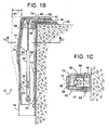
- a loading dock platform 10 is provided with a bumper assembly 12 having a moveable bumper 14, as shown in Figures 1A and 1B through 3A and 3B .
- bumper assembly 12 includes a bumper frame 16 (a generally U-shaped channel) that is anchored to dock 10, preferably between a dock leveler 18 and a conventional bumper 20, although bumper assembly 12 can be used without conventional bumper 20.
- the conventional bumper 20 helps prevent trucks and trailers of low or standard height from backing up against the building or getting so close as to obstruct the operation of dock leveler 18; while bumper 14, being moveable relative to frame 16, is able to rise above platform 10 to help prevent higher vehicles and swap body containers from backing up and over dock platform 10.
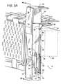
- Figures 1A and 1B show bumper 14 in its lowered, stored position, while Figures 2A and 2B show bumper 14 in its raised, operative position.
- pin 22 extending from a mounting surface 24 of bumper 14 slides within a slot 26 in frame 16.
- a smaller second pin 28 extending from bumper 14 also moves within the constraint of slot 26 to limit the extent to which bumper 14 may swing outward from frame 16.
- pin 28 limits the outward movement of bumper 14 to about one or two inches, as indicated by dimension 30. If desired, pin 28 may serve as a replaceable weak link should bumper 14 ever be forced outward beyond its normal limit.
- bumper 14 is urged to its operative position by a force 32 that is provided by at least one of a mechanical spring force, a gas spring force, gravity, hydraulic actuation, pneumatic actuation, and electromotive actuation.
- force 32 is provided by an actuator 34, such as a normally retracted gas spring 36 that connects pin 22 of bumper 14 to a stationary point 38 on plate 40 of bumper frame 16 (see Figure 1C ).
- Actuator 34 is schematically illustrated to represent any type of powered actuator such as those employing hydraulic, pneumatic, or electromotive actuation, and to further represent any type of non-powered spring.
- a latching mechanism is employed, specifically latch 42 engages pin 22. Pivoting latch 42 counterclockwise about a pin 44 releases pin 22, which allows actuator 34 to lift bumper 14 to its raised, operative position.
- the actuation of latch 42 can be carried out by numerous devices including, but not limited to, a solenoid, a pneumatic or hydraulic cylinder, or a linkage mechanically coupling the operation of the bumper to that of dock leveler 18 or the movement of a vehicle at dock 10.
- a foot-actuated release mechanism 46 operates latch 42. Release mechanism 46 includes a bar 48 having slots 50 that slidingly engage pins or bolts 52 and 54 that protrude from frame 16.
- actuation can also accomplished by a variety of other actions including, but not limited to, an overhead door descending to a closed position. Using a door for actuation could automatically raise a bumper as the door closes.
- an angled protrusion 64 on mounting surface 24 engages an angled block 66 that is pivotally connected to frame 16 by way of a pin 68.
- Protrusion 64 engaging block 66 forces bumper 14 outward.
- the upper movement of bumper 14 can be limited by any one of a variety of travel limiting devices, such as the travel limit of actuator 34 itself or a cross bar 70 on mounting surface 24 engaging a stop 72 that is disposed on frame 16.
- bumper 14 can be returned to its stored position by a powered actuator 34 or by the application of a manual force, such as by pushing down against a foot-receiving member 74 on bumper 14.
- a powered actuator 34 or by the application of a manual force, such as by pushing down against a foot-receiving member 74 on bumper 14.
- a manual force such as by pushing down against a foot-receiving member 74 on bumper 14.
- bumper 14 may first need to be moved to a retracted position away from the parked vehicle or swap body.
- bumper 14 is moved in a direction that traverses bumper face 76 (in this case, in a rearward direction relative to the vehicle) by first pivoting block 66 downward, away from protrusion 64, as shown in Figures 3A and 3B .
- a manually held pipe 78 ( Figure 2B ) temporarily engaging a short lever 80 on block 66 can help provide the necessary leverage to manually rotate block 66.
- bar 66 pivoted downward and disengaged from protrusion 64 bumper 14 is now free to move back and away from the vehicle or container that may be parked at dock 10.
- bumper 14 is readily pushed back down to its stored position by applying downward pressure against foot-receiving member 74.
- a tapered portion 81 of latch 42 allows pin 22 to snap underneath latch 42, which holds bumper 14 in its stored position after pressure on foot-receiving member 74 is released.
- a tension spring 82 urges block 66 to its position shown in Figure 1B .
- a release mechanism is thus provided which, in this embodiment, comprises a block 66 and protrusion 64.
- the release mechanism prevents the bumper 14 from moving in a direction that traverses the bumper face 76 (i.e. in a rearward direction relative to the vehicle).
- the release mechanism may also provide a load path for reacting the force applied by the vehicle to the bumper back into a fixed structure such as the loading dock.
- the release mechanism also has a second, release configuration ( Fig. 3B ) in which it permits movement of the bumper 14 in a rearward direction - so that the retracted bumper can be returned to a stored position.
- the release mechanism is configurable between its first, support configuration and its second, release configuration by virtue of rotation of block 66 about pin 68. This rotation is facilitated by use of lever 80 acting on block 66.
- bumper 14 is normally left in its raised, operative position of Figures 2A and 2B .
- the release mechanism can be placed in its release configuration by block 66 being rotated to release the pressure against bumper 14 and allow bumper 14 to be pushed back down to its stored position of Figures 1A and 1B . Since the remaining presence of a bumper above the loading dock surface would otherwise be an impediment to the loading process, the ability of the present bumper to be released and return to a stored position (even when pressure is being applied to the bumper face) is a valuable feature of this design, and (in part) distinguishes this design over those non existing.
- the vehicle or container is then loaded or unloaded as needed. After the vehicle departs or the container is removed, an operator steps on foot-receiving member 56 to allow bumper 14 to return to its raised, operative position of Figures 2A and 2B .
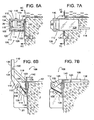
- a bumper assembly 84 includes a bumper 86 that provides movement transverse to the bumper face by manually rotating between an operative position of Figures 4A - 4C and a stored position of Figures 5A - 5B , that is by rotation about an axis that is generally vertical (more vertical than horizontal).
- the rotation is provided by a pin 88 that extends downward from a base structure 90 and slips into a sleeve 92 that is embedded in dock 10 at a slight angle. The angle urges bumper 86 to swing towards its operative position of Figures 4A - 4C .
- a lip 94 extending from base 90 slips underneath a mating lip 96 that is fixed relative to dock 10.
- a latch 98 pivots about a pin 100 in base 90 to catch a forward surface 102 of lip 96. Lip 96 engaging latch 98 and lip 94 holds bumper 14 in its operative position.
- the release mechanism comprises lever 104 and lip 96/surface 102.
- the mechanism prevents bumper 86 from moving transversely to the bumper face.
- disengagement of lever 104 from surface 102 permits the transverse movement.
- Bumper 86 can be held in its stored position by virtue of the bumper's rotation simply being at its top-dead-center, or if desired, an obvious detent, stop, or latch can be provided at this position.
- bumper assembly 84 at its stored and operative positions is similar to that of bumper assembly 12.
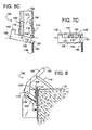
- a bumper assembly 106 includes a bumper 108 that provides movement transverse to the bumper face by manually rotating between an operative position of Figures 6A - 6C and a stored position of Figures 7A - 7C , that is, by movement of the bumper face between a generally vertical operative position and a generally horizontal stored position.
- a bumper mounting structure 110 includes two arms 112 that are rotatably pinned to a fixed bumper frame 114 via a pin 116.
- a brace 118 is pivotally connected to structure 11C by way of a pin 120.
- a lower end 122 of brace 118 rests atop a fixed L-shaped support plate 124 and engages a pivoting plate 126 (see Figure 6C ) to help hold bumper 108 in its raised operative position against the downward urging of a tension spring 128 and/or the pressure a vehicle or container pushing against an abutment face 130 of bumper 108.
- Brace 118 can also tuck underneath structure 110 when bumper 108 is in its stored position.
- plate 126 pivots about a fixed pin 130 to cause a latch 132 to engage a lip 134 on structure 110 (see Figure 7C ).
- Latch 132 engaging lip 134 holds bumper 108 in its stored position against the upward urging of spring 128.
- Spring 128 is connected at points 136 and 138, which are positioned to provide bumper 108 with an equilibrium position, as shown in Figure 8 . Such a retracted or intermediate position prevents bumper 108 from slamming to either of its operative or stored positions. Thus, bumper 108 is manually moved from its intermediate position to its operative and stored positions by pushing up or down against an upper portion of bumper 108. In this embodiment, the upper portion of bumper 108 serves as a foot-receiving member 140.
- an operator depresses a foot-receiving member 142 that extends from plate 126.
- Depressing member 142 when bumper 108 is in its operative position rotates plate 126 about pin 130 to lower an upper edge 144 of plate 126 below support plate 124. This allows lower end 122 of brace 118 to slide from support plate 124 and over onto dock platform 10, thus allowing spring 128 to pull bumper 108 down to its intermediate position.
- the release mechanism here thus includes plate 126 and brace 118.
- bumper 108 in its stored position may have an objectionable projection above dock platform 10.
- platform 10 can be provided with a recess or depression (not shown) to allow bumper 108 to store with its upper surface in a flush relationship with dock surface 10.
- Figures 9-12 illustrates a bumper assembly 152 that is similar to bumper assembly 12, but is provided with different actuation and latch/release mechanisms.
- Figure 9 shows assembly 152 with a bumper 14' latched in a stored position;
- Figure 10 and 11 illustrate a raised, operative position;
- Figure 12 shows bumper 14' being released from its operative position;
- Figure 13 illustrates a retracted position.
- an actuator 34' such as a normally extended gas spring 36' is used.
- Gas spring 36' has one pin connection 156 on a lug 158 that is fixed relative to bumper 14' and has another pin connection 160 that is fixed relative to a frame 16'. Gas spring 36' urges pins 156 and 160 apart, thus urging bumper 14' upward.
- Latch mechanism 162 To hold bumper 14' down at its stored position, against the urging of spring 36', a latch mechanism 162 is disposed near the upper end of bumper assembly 152.
- Latch mechanism 162 includes a catch 164 that is attached to a top plate 166 of bumper 154 and releasably engages a lever-actuated hook 168 that pivots about a pin 170.
- a tension spring 172 urges hook 168 to engage catch 164.
- lever-actuated hook 168 is pushed down, as indicated by arrow 174, which disengages latch mechanism 162.
- pin 22 reaching the top of slot 26 limits the upward travel of bumper 14', thus eliminating the need for stops 70 and 72 of bumper assembly 12.
- the outward pivotal motion of bumper 14' can be limited by a U-shaped bar 176 attached to frame 16' and a heal plate 178 attached to bumper 14'. The pivoting of bumper 14' can then be limited by bar 176 engaging bumper 14' or by heal plate 178 engaging frame 16'. It should also be noted that limiting a bumper's outward pivotal motion or upward travel in the manners just described could be applied to either bumper assembly 12 or 152.
- Disengaging latch 162 also allows a spring-loaded hinge 180 to pivot upper plate 166 upward relative to bumper 14'.
- the upward pivotal motion of plate 166 lifts a push arm 182 that can later be used to help release bumper 14' from its operative position.
- a push arm 182 that can later be used to help release bumper 14' from its operative position.
- bumper 14' can be moved away from truck 21 in a direction that traverses abutment face 76 by first pushing down on top plate 166, as indicated by arrow 184 of Figure 12 .
- bumper 14' can be readily pushed down from its retracted position of Figure 13 back to its stored position of Figure 9 . This can be done manually by pushing down on top plate 166, or can be done automatically by an overhead door pushing down on plate 166 as the door descends to a closed position.
- push arm 182 can vary, however, in a preferred embodiment the upper portion of arm 182 is guided by a U-shaped guide 188 that is narrow enough to slip between a slot 190 in block 66, as shown in Figure 11 .
- the width of butt 186 can slip between the two angled protrusions 64, but is too wide for slot 190 of block 66. This allows butt 186 to recede between protrusions 64 as bumper 14' ascends from its stored to operative position.
- an upper beveled portion 192 of butt 186 rides along a lower tapered portion 194 of block 66, which pushes butt 186 between protrusions 64.
- Butt 186 is preferably biased toward block 66 to ensure that butt 186 upon descending can engage the top of block 66 for releasing bumper 14' from its operative position.
- Such biasing can be readily accomplished by spring force or by gravity in conjunction with the shape and pivot location (e.g., point 196) of arm 182.
Landscapes
- Engineering & Computer Science (AREA)
- Mechanical Engineering (AREA)
- Fittings On The Vehicle Exterior For Carrying Loads, And Devices For Holding Or Mounting Articles (AREA)
- Handcart (AREA)
- Lighting Device Outwards From Vehicle And Optical Signal (AREA)
- Moulds For Moulding Plastics Or The Like (AREA)
- Lock And Its Accessories (AREA)
- Injection Moulding Of Plastics Or The Like (AREA)
Claims (16)
- Assemblage de butoir adapté pour mettre en prise un transporteur de marchandises (21) à une plate-forme de quai de chargement (10), comprenant :■ un châssis (16) qui peut être attaché selon une orientation sensiblement fixe à la plate-forme de quai (10) ; et■ un butoir (14 ; 108 ; 14') couplé au châssis et comprenant une face de butée (76) mobile à partir d'une position opérationnelle au-dessus de la plate-forme de quai (10) jusqu'à une position de stockage en dessous de la position opérationnelle, dans lequel la face de butée (76) est adaptée pour être mise en prise par le transporteur de marchandises (21) lorsque le butoir (14 ; 108 ; 14') est dans la position opérationnelle, caractérisé en ce que ladite face de butée (76) est également mobile à partir de ladite position opérationnelle jusqu'à une position rétractée dans une direction vers l'arrière par rapport au transporteur de marchandises et dans lequel le butoir (14 ; 108 ; 14') peut tourner autour d'une broche (22, 116) raccordée au châssis, de sorte qu'il tourne autour d'un axe sensiblement horizontal pendant le mouvement entre la position opérationnelle et la position rétractée.
- Assemblage de butoir selon la revendication 1, dans lequel le butoir (14 ; 108 ; 14') est au-dessus de la plate-forme de quai (10) lorsque le butoir (14 ; 108 ; 14') est dans la position rétractée.
- Assemblage de butoir selon la revendication 1, comprenant, en outre, un mécanisme de verrouillage (42 ; 46) pour maintenir le butoir (14 ; 108 ; 14') dans une position de stockage en dessous de la position opérationnelle.
- Assemblage de butoir selon la revendication 3, dans lequel le mécanisme de verrouillage déclenche le déplacement du butoir (14 ; 108 ; 14') depuis la position de stockage jusqu'à la position opérationnelle.
- Assemblage de butoir selon la revendication 3, dans lequel le mécanisme de verrouillage est actionné par le pied.
- Assemblage de butoir selon la revendication 1, comprenant, en outre, un organe de réception de pied couplé au butoir (14 ; 108 ; 14'), dans lequel l'application d'une force appropriée à l'organe de réception de pied déplace le butoir (14 ; 108 ; 14') entre sa position opérationnelle et sa position de stockage.
- Assemblage de butoir selon la revendication 1, comprenant, en outre, un actionneur de puissance (34) couplé au butoir (14 ; 108 ; 14') pour déplacer le butoir (14 ; 108 ; 14') entre sa position opérationnelle et sa position de stockage, dans lequel l'actionneur de puissance emploie au moins l'une de la commande hydraulique, de la commande pneumatique et de la commande électromotrice.
- Assemblage de butoir selon la revendication 1, dans lequel le butoir (14 ; 108 ; 14') est poussé jusqu'à sa position opérationnelle par au moins l'une de la force de ressort mécanique, de la force de ressort au gaz et de la gravité.
- Assemblage de butoir selon la revendication 1, dans lequel le butoir (14 ; 108 ; 14') est couplé au châssis pour un déplacement allant de la position opérationnelle jusqu'à la position rétractée et est, en outre, mobile jusqu'à une position de stockage en dessous de la position opérationnelle, dans lequel le butoir (14 ; 108 ; 14') s'étend au-dessus de la plate-forme de quai (10) à la fois à la position opérationnelle et à la position rétractée.
- Assemblage de butoir selon la revendication 9, dans lequel le butoir (14 ; 108 ; 14') se déplace généralement de manière linéaire entre la position opérationnelle et la position de stockage.
- Assemblage de butoir selon la revendication 9, comprenant, en outre, un mécanisme de verrouillage pour maintenir le butoir (14 ; 108 ; 14') dans une position de stockage en dessous de la position opérationnelle.
- Assemblage de butoir selon la revendication 11, dans lequel le mécanisme de verrouillage déclenche le déplacement du butoir (14 ; 108 ; 14') depuis la position de stockage jusqu'à la position opérationnelle.
- Assemblage de butoir selon la revendication 11, dans lequel le mécanisme de verrouillage est actionné par le pied.
- Assemblage de butoir selon la revendication 11, comprenant, en outre, un organe de réception de pied couplé au butoir (14 ; 108 ; 14'), dans lequel l'application d'une force appropriée à l'organe de réception de pied déplace le butoir (14 ; 108 ; 14') entre sa position opérationnelle et sa position de stockage.
- Assemblage de butoir selon la revendication 9, dans lequel le butoir (14 ; 108 ; 14') est poussé jusqu'à sa position opérationnelle par au moins l'une de la force de ressort mécanique, de la force de ressort au gaz et de la gravité.
- Procédé de réception d'un transporteur de marchandises (21) à une plate-forme de quai de chargement (10), comprenant les étapes consistant à :■ positionner un butoir (14 ; 108 ; 14') dans une position opérationnelle au-dessus de la plate-forme de quai de chargement (10) où une face de butée (76) du butoir (14 ; 108 ; 14') peut être mise en prise par le transporteur de marchandises (21), et■ déplacer le butoir (14 ; 108 ; 14') de la position opérationnelle à une position rétractée dans une direction vers l'arrière par rapport à la position opérationnelle et, en outre, déplacer le butoir (14 ; 108 ; 14') jusqu'à une position de stockage en dessous de la position opérationnelle, dans laquelle le butoir (14 ; 108 ; 14') peut tourner autour d'une broche (22 ; 116) raccordée au châssis de sorte qu'elle tourne entre la position opérationnelle et la position rétractée.
Applications Claiming Priority (3)
| Application Number | Priority Date | Filing Date | Title |
|---|---|---|---|
| US09/552,953 US6497076B1 (en) | 2000-04-20 | 2000-04-20 | Moveable bumper for a loading dock |
| US552953 | 2000-04-20 | ||
| PCT/US2001/040531 WO2001081215A1 (fr) | 2000-04-20 | 2001-04-13 | Butoir amovible pour quai de chargement |
Publications (3)
| Publication Number | Publication Date |
|---|---|
| EP1282574A1 EP1282574A1 (fr) | 2003-02-12 |
| EP1282574B1 EP1282574B1 (fr) | 2005-03-30 |
| EP1282574B2 true EP1282574B2 (fr) | 2008-12-17 |
Family
ID=24207506
Family Applications (1)
| Application Number | Title | Priority Date | Filing Date |
|---|---|---|---|
| EP01929057A Expired - Lifetime EP1282574B2 (fr) | 2000-04-20 | 2001-04-13 | Butoir amovible pour quai de chargement |
Country Status (7)
| Country | Link |
|---|---|
| US (1) | US6497076B1 (fr) |
| EP (1) | EP1282574B2 (fr) |
| AT (1) | ATE292078T1 (fr) |
| AU (1) | AU2001255843A1 (fr) |
| CA (1) | CA2406868A1 (fr) |
| DE (1) | DE60109764T3 (fr) |
| WO (1) | WO2001081215A1 (fr) |
Families Citing this family (24)
| Publication number | Priority date | Publication date | Assignee | Title |
|---|---|---|---|---|
| US6634049B2 (en) * | 2001-05-07 | 2003-10-21 | Rite-Hite Holding Corporation | Moveable bumper for a dock leveler |
| US20050102929A1 (en) * | 2002-07-26 | 2005-05-19 | Hoffmann David J. | Seal for a loading dock bumper |
| DE10305565A1 (de) * | 2003-02-10 | 2004-08-19 | Niclas Grunewald | Vorrichtung zur Dichtung eines Spaltes zwischen dem Rand einer Überladebrücke und eines Fahrzeuges |
| EP1594783B1 (fr) * | 2003-02-10 | 2012-06-13 | Niclas Grunewald | Protection anti-tamponnement |
| US6739011B1 (en) * | 2003-03-07 | 2004-05-25 | Industrial Dock Equipment, Llc | Vertically movable dock bumper device |
| FR2855195B1 (fr) * | 2003-05-19 | 2005-08-19 | Peugeot Citroen Automobiles Sa | Dispositif de protection d'un quai de chargement ou de dechargement d'un vehicule et quai de chargement ou de dechargement equipe d'un tel dispositif de protection. |
| US7043790B2 (en) * | 2003-05-27 | 2006-05-16 | Spx Dock Products, Inc. | Vertically-storing dock leveler apparatus and method |
| US7444785B2 (en) * | 2003-09-10 | 2008-11-04 | Fairborn Usa, Inc. | Bottom pad/bumper assembly for loading docks with leveler |
| US20050254902A1 (en) * | 2004-05-17 | 2005-11-17 | Rude Richard J | Protective cover for marine mooring bumper |
| US8181759B2 (en) * | 2005-12-29 | 2012-05-22 | Rite-Hite Holding Corporation | Loading dock bumper with two-phase resistance |
| US7584943B2 (en) * | 2005-12-29 | 2009-09-08 | Frommelt Industries Of Canada, Inc. | Loading dock bumper with replaceable metal faceplate |
| US20070152389A1 (en) * | 2005-12-29 | 2007-07-05 | Kloppenburg Hans J | Metal retrofit kit for a loading dock bumper |
| CA2666700A1 (fr) * | 2008-05-28 | 2009-11-28 | Joseph J. Di Biase | Ensemble de butoirs de quai actionnes par une charge |
| ES2362600B1 (es) * | 2009-12-22 | 2012-03-07 | Amiserru, S.L. | Muelle de carga. |
| AU2010257436B2 (en) * | 2010-01-04 | 2016-08-11 | Steven John Cowey | Retaining means for a fender assembly |
| WO2013120914A1 (fr) | 2012-02-13 | 2013-08-22 | Mcr Consortium Limited | Ensemble de rampe d'accostage |
| USD712112S1 (en) | 2013-05-28 | 2014-08-26 | Grant Leum | Low-profile lip extender unit for a dock ramp |
| IES20130231A2 (en) * | 2013-08-01 | 2015-07-01 | Esidock Ltd | A dock ramp assembly and bumper assembly |
| US8875440B1 (en) | 2013-09-24 | 2014-11-04 | Jose Duran | Rotatable barrier for retaining a vehicle in a railroad boxcar during loading procedures |
| DE102014105145B4 (de) | 2014-01-31 | 2020-07-02 | Hörmann Alkmaar Bv | Anfahrpuffervorrichtung |
| FR3035093B1 (fr) * | 2015-04-20 | 2018-01-19 | Gpsystems | Dispositif de butoir escamotable pour installation de quai de chargement, installation de quai le comprenant et procede d'utilisation correspondant |
| US9790038B2 (en) | 2016-02-02 | 2017-10-17 | Rite-Hite Holding Corporation | Bumpers for use at loading docks |
| FR3047479B1 (fr) | 2016-02-04 | 2018-03-02 | Gpsystems | Dispositif de butoir escamotable pour quai de chargement et/ou dechargement de vehicule |
| NL2017922B1 (en) * | 2016-12-05 | 2018-06-18 | Stertil Bv | Bumper and dock comprising a bumper guide with activation path and lock, and method for loading/unloading a vehicle at the dock |
Citations (3)
| Publication number | Priority date | Publication date | Assignee | Title |
|---|---|---|---|---|
| DE9201381U1 (de) † | 1992-02-05 | 1992-04-23 | Van Wijk Nederland B.V., Lelystad | Anfahrpuffer für Rampen |
| DE29503742U1 (de) † | 1995-01-27 | 1995-06-22 | Gebr. Koch GmbH + Co., 32791 Lage | Anfahrpuffer für Verladerampen |
| DE29804117U1 (de) † | 1998-03-09 | 1998-05-14 | Van Wijk Nederland B.V., Lelystad | Rampenpuffer mit verschiebbarem Teil |
Family Cites Families (30)
| Publication number | Priority date | Publication date | Assignee | Title |
|---|---|---|---|---|
| US3203002A (en) | 1964-12-07 | 1965-08-24 | Kelley Co Inc | Adjustable dockboard with counterbalancing extension lip |
| GB1161537A (en) | 1967-03-30 | 1969-08-13 | T & S Equipment Company | Loading Ramp |
| US3375625A (en) * | 1967-05-24 | 1968-04-02 | Medalist Ind Inc | Door seal |
| US3440673A (en) | 1968-02-15 | 1969-04-29 | Kelley Co Inc | Dockboard |
| US3493984A (en) | 1968-04-29 | 1970-02-10 | Raymond T Reinhard | Dock leveler |
| US3570033A (en) | 1969-04-28 | 1971-03-16 | Adrian P Hovestad | Dockboards |
| US3665997A (en) * | 1970-02-20 | 1972-05-30 | Overhead Door Corp | Adjustable dock seal assembly |
| US3644952A (en) * | 1970-07-29 | 1972-02-29 | Stanray Corp | Canopy frame assembly for cab of airplane loading and unloading ramp |
| US3840930A (en) | 1972-03-10 | 1974-10-15 | R Wanddell | Dockboard |
| US3921241A (en) | 1974-04-08 | 1975-11-25 | Overhead Door Corp | Dockboard support |
| DE2800128C2 (de) | 1978-01-03 | 1982-07-01 | Kurt 3015 Wennigsen Alten | Überfahrbrücke für Rampen |
| DE3015717C2 (de) | 1980-04-24 | 1983-12-29 | Kurt 3015 Wennigsen Alten | Überladebrücke für Rampen |
| DE3018932A1 (de) | 1980-05-17 | 1981-11-26 | Trepel Ag, 6200 Wiesbaden | Ueberfahrbruecke fuer rampen |
| US4682382A (en) | 1986-01-06 | 1987-07-28 | Kelley Company Inc. | Weather seal for a loading dock pit |
| US4744121A (en) | 1987-02-20 | 1988-05-17 | Rite-Hite Corporation | Loading dock and hydraulic system therefor |
| US5088143A (en) | 1990-12-04 | 1992-02-18 | The Serco Corporation | Dock leveler lip actuation mechanism |
| DE4204440C2 (de) | 1992-02-14 | 1997-08-14 | Agfa Gevaert Ag | Vorrichtung zum Entfernen von Behandlungsflüssigkeit von der Rückseite eines fotografischen, bandförmigen Schichtträgers |
| US5452489A (en) | 1993-09-21 | 1995-09-26 | Systems, Inc. | Dock leveler with automatic end barrier |
| US5450643A (en) | 1993-10-04 | 1995-09-19 | Kelley Company Inc. | Edge-of-dock leveler |
| US5481774A (en) | 1993-10-04 | 1996-01-09 | Kelley Company, Inc. | Support mechanism for a dockleveler lift bag |
| US5658633A (en) | 1995-09-18 | 1997-08-19 | Frommelt Industries Of Canada Inc. | Loading dock bumpers |
| US5644812A (en) | 1995-10-26 | 1997-07-08 | Neufeldt Industrial Services, Inc. | Adjustable dock apparatus |
| DE29600207U1 (de) | 1996-01-08 | 1996-02-29 | Alten Gerätebau GmbH, 30974 Wennigsen | Rampenanschlagpuffer für andockende Fahrzeuge |
| DE19612135A1 (de) | 1996-03-27 | 1997-10-02 | Trepel Hebe Foerdertech | Überfahrbrücke für Rampen sowie Verfahren zum Betreiben der Überfahrbrücke |
| US5775044A (en) | 1996-05-07 | 1998-07-07 | Styba; Loren K. | Loading dock having a split dock seal |
| US5881414A (en) | 1996-11-27 | 1999-03-16 | United Dominion Ind., Inc. | Loading dock with adjustable bumpers |
| US6006389A (en) | 1996-11-27 | 1999-12-28 | United Dominion Ind., Inc. | Loading dock with adjustable bumpers |
| US5832554A (en) | 1997-02-18 | 1998-11-10 | United Dominion Industries, Inc. | Dock leveler with cam assisted lip extension |
| DE29716877U1 (de) | 1997-09-19 | 1998-01-08 | Deierling, Eberhard, 31275 Lehrte | Überladebrücke zur Bildung einer Überbrückung zwischen Gebäuden und Ladeflächen |
| US6070283A (en) | 1998-07-10 | 2000-06-06 | Rite-Hite Holding Corporation | Dock leveler with integral bumpers |
-
2000
- 2000-04-20 US US09/552,953 patent/US6497076B1/en not_active Expired - Fee Related
-
2001
- 2001-04-13 AU AU2001255843A patent/AU2001255843A1/en not_active Abandoned
- 2001-04-13 EP EP01929057A patent/EP1282574B2/fr not_active Expired - Lifetime
- 2001-04-13 WO PCT/US2001/040531 patent/WO2001081215A1/fr not_active Ceased
- 2001-04-13 DE DE60109764T patent/DE60109764T3/de not_active Expired - Fee Related
- 2001-04-13 AT AT01929057T patent/ATE292078T1/de not_active IP Right Cessation
- 2001-04-13 CA CA002406868A patent/CA2406868A1/fr not_active Abandoned
Patent Citations (4)
| Publication number | Priority date | Publication date | Assignee | Title |
|---|---|---|---|---|
| DE9201381U1 (de) † | 1992-02-05 | 1992-04-23 | Van Wijk Nederland B.V., Lelystad | Anfahrpuffer für Rampen |
| FR2686913A1 (fr) † | 1992-02-05 | 1993-08-06 | Wijk Nederland | Amortisseur de tamponnement pour quais. |
| DE29503742U1 (de) † | 1995-01-27 | 1995-06-22 | Gebr. Koch GmbH + Co., 32791 Lage | Anfahrpuffer für Verladerampen |
| DE29804117U1 (de) † | 1998-03-09 | 1998-05-14 | Van Wijk Nederland B.V., Lelystad | Rampenpuffer mit verschiebbarem Teil |
Also Published As
| Publication number | Publication date |
|---|---|
| WO2001081215A1 (fr) | 2001-11-01 |
| CA2406868A1 (fr) | 2001-11-01 |
| DE60109764D1 (de) | 2005-05-04 |
| EP1282574A1 (fr) | 2003-02-12 |
| EP1282574B1 (fr) | 2005-03-30 |
| DE60109764T2 (de) | 2005-09-15 |
| DE60109764T3 (de) | 2009-05-07 |
| ATE292078T1 (de) | 2005-04-15 |
| AU2001255843A1 (en) | 2001-11-07 |
| US6497076B1 (en) | 2002-12-24 |
Similar Documents
| Publication | Publication Date | Title |
|---|---|---|
| EP1282574B2 (fr) | Butoir amovible pour quai de chargement | |
| US4695216A (en) | Vehicle restraint | |
| EP1012091B1 (fr) | Appareil de mise a niveau dote d'un systeme a bequille de securite | |
| US4665579A (en) | Counterbalancing mechanism for an edge-of-dock dockboard | |
| CA1295443C (fr) | Dispositif d'immobilisation pour vehicule, a mouvement de translation et tournant | |
| US5440772A (en) | Vehicle-activated safety leg control system for a dock leveler assembly | |
| US4488325A (en) | Truck locking device | |
| US4865507A (en) | Dock leveler assembly and latch mechanism therefor | |
| US3728753A (en) | Dockboard | |
| CA2380251C (fr) | Levre de rampe de quai a deverrouillage automatique et descente freinee | |
| US7431546B2 (en) | Device for securing a personal-transport vehicle to a mounting surface | |
| US6634049B2 (en) | Moveable bumper for a dock leveler | |
| US4531248A (en) | Dockboard assembly | |
| US20050015900A1 (en) | Vertically-storing dock leveler apparatus and method | |
| US5203663A (en) | Vehicle restraining mechanism | |
| US4375932A (en) | Powered cargo restraint | |
| CA2365983C (fr) | Dispositif d'arrimage de fret | |
| US7032267B2 (en) | Dock leveler with combination safety leg and lip deflector | |
| US5586356A (en) | Automatic return to dock mechanism for mechanical dock leveler | |
| CA2698923A1 (fr) | Dispositifs encastres de retenue de vehicule | |
| US5157801A (en) | Dock leveler having automatically actuated vehicle barrier | |
| US6439823B1 (en) | Vehicle restraint device | |
| US3516103A (en) | Dockboard | |
| US6629328B2 (en) | Universal lip lifting device | |
| JP2003137016A (ja) | 貨物自動車におけるテールゲートリフト |
Legal Events
| Date | Code | Title | Description |
|---|---|---|---|
| PUAI | Public reference made under article 153(3) epc to a published international application that has entered the european phase |
Free format text: ORIGINAL CODE: 0009012 |
|
| 17P | Request for examination filed |
Effective date: 20021025 |
|
| AK | Designated contracting states |
Designated state(s): AT BE CH CY DE DK ES FI FR GB GR IE IT LI LU MC NL PT SE TR |
|
| AX | Request for extension of the european patent |
Extension state: AL LT LV MK RO SI |
|
| 17Q | First examination report despatched |
Effective date: 20030801 |
|
| GRAP | Despatch of communication of intention to grant a patent |
Free format text: ORIGINAL CODE: EPIDOSNIGR1 |
|
| GRAS | Grant fee paid |
Free format text: ORIGINAL CODE: EPIDOSNIGR3 |
|
| GRAA | (expected) grant |
Free format text: ORIGINAL CODE: 0009210 |
|
| AK | Designated contracting states |
Kind code of ref document: B1 Designated state(s): AT BE CH CY DE DK ES FI FR GB GR IE IT LI LU MC NL PT SE TR |
|
| PG25 | Lapsed in a contracting state [announced via postgrant information from national office to epo] |
Ref country code: IT Free format text: LAPSE BECAUSE OF FAILURE TO SUBMIT A TRANSLATION OF THE DESCRIPTION OR TO PAY THE FEE WITHIN THE PRESCRIBED TIME-LIMIT;WARNING: LAPSES OF ITALIAN PATENTS WITH EFFECTIVE DATE BEFORE 2007 MAY HAVE OCCURRED AT ANY TIME BEFORE 2007. THE CORRECT EFFECTIVE DATE MAY BE DIFFERENT FROM THE ONE RECORDED. Effective date: 20050330 Ref country code: BE Free format text: LAPSE BECAUSE OF FAILURE TO SUBMIT A TRANSLATION OF THE DESCRIPTION OR TO PAY THE FEE WITHIN THE PRESCRIBED TIME-LIMIT Effective date: 20050330 Ref country code: TR Free format text: LAPSE BECAUSE OF FAILURE TO SUBMIT A TRANSLATION OF THE DESCRIPTION OR TO PAY THE FEE WITHIN THE PRESCRIBED TIME-LIMIT Effective date: 20050330 Ref country code: LI Free format text: LAPSE BECAUSE OF FAILURE TO SUBMIT A TRANSLATION OF THE DESCRIPTION OR TO PAY THE FEE WITHIN THE PRESCRIBED TIME-LIMIT Effective date: 20050330 Ref country code: AT Free format text: LAPSE BECAUSE OF FAILURE TO SUBMIT A TRANSLATION OF THE DESCRIPTION OR TO PAY THE FEE WITHIN THE PRESCRIBED TIME-LIMIT Effective date: 20050330 Ref country code: FI Free format text: LAPSE BECAUSE OF FAILURE TO SUBMIT A TRANSLATION OF THE DESCRIPTION OR TO PAY THE FEE WITHIN THE PRESCRIBED TIME-LIMIT Effective date: 20050330 Ref country code: CH Free format text: LAPSE BECAUSE OF FAILURE TO SUBMIT A TRANSLATION OF THE DESCRIPTION OR TO PAY THE FEE WITHIN THE PRESCRIBED TIME-LIMIT Effective date: 20050330 |
|
| REG | Reference to a national code |
Ref country code: GB Ref legal event code: FG4D |
|
| REG | Reference to a national code |
Ref country code: CH Ref legal event code: EP |
|
| PG25 | Lapsed in a contracting state [announced via postgrant information from national office to epo] |
Ref country code: LU Free format text: LAPSE BECAUSE OF NON-PAYMENT OF DUE FEES Effective date: 20050413 Ref country code: IE Free format text: LAPSE BECAUSE OF NON-PAYMENT OF DUE FEES Effective date: 20050413 Ref country code: CY Free format text: LAPSE BECAUSE OF FAILURE TO SUBMIT A TRANSLATION OF THE DESCRIPTION OR TO PAY THE FEE WITHIN THE PRESCRIBED TIME-LIMIT Effective date: 20050413 |
|
| PG25 | Lapsed in a contracting state [announced via postgrant information from national office to epo] |
Ref country code: MC Free format text: LAPSE BECAUSE OF NON-PAYMENT OF DUE FEES Effective date: 20050430 |
|
| REF | Corresponds to: |
Ref document number: 60109764 Country of ref document: DE Date of ref document: 20050504 Kind code of ref document: P |
|
| REG | Reference to a national code |
Ref country code: IE Ref legal event code: FG4D |
|
| PG25 | Lapsed in a contracting state [announced via postgrant information from national office to epo] |
Ref country code: DK Free format text: LAPSE BECAUSE OF FAILURE TO SUBMIT A TRANSLATION OF THE DESCRIPTION OR TO PAY THE FEE WITHIN THE PRESCRIBED TIME-LIMIT Effective date: 20050630 Ref country code: GR Free format text: LAPSE BECAUSE OF FAILURE TO SUBMIT A TRANSLATION OF THE DESCRIPTION OR TO PAY THE FEE WITHIN THE PRESCRIBED TIME-LIMIT Effective date: 20050630 |
|
| PG25 | Lapsed in a contracting state [announced via postgrant information from national office to epo] |
Ref country code: ES Free format text: LAPSE BECAUSE OF FAILURE TO SUBMIT A TRANSLATION OF THE DESCRIPTION OR TO PAY THE FEE WITHIN THE PRESCRIBED TIME-LIMIT Effective date: 20050711 |
|
| PG25 | Lapsed in a contracting state [announced via postgrant information from national office to epo] |
Ref country code: PT Free format text: LAPSE BECAUSE OF FAILURE TO SUBMIT A TRANSLATION OF THE DESCRIPTION OR TO PAY THE FEE WITHIN THE PRESCRIBED TIME-LIMIT Effective date: 20050908 |
|
| REG | Reference to a national code |
Ref country code: CH Ref legal event code: PL |
|
| PLBI | Opposition filed |
Free format text: ORIGINAL CODE: 0009260 |
|
| PLAX | Notice of opposition and request to file observation + time limit sent |
Free format text: ORIGINAL CODE: EPIDOSNOBS2 |
|
| 26 | Opposition filed |
Opponent name: NANI VERLADETECHNIK GMBH & CO. KG Effective date: 20051228 |
|
| PGFP | Annual fee paid to national office [announced via postgrant information from national office to epo] |
Ref country code: NL Payment date: 20060403 Year of fee payment: 6 |
|
| PGFP | Annual fee paid to national office [announced via postgrant information from national office to epo] |
Ref country code: GB Payment date: 20060412 Year of fee payment: 6 |
|
| NLR1 | Nl: opposition has been filed with the epo |
Opponent name: NANI VERLADETECHNIK GMBH & CO. KG |
|
| EN | Fr: translation not filed | ||
| PLAF | Information modified related to communication of a notice of opposition and request to file observations + time limit |
Free format text: ORIGINAL CODE: EPIDOSCOBS2 |
|
| PLBB | Reply of patent proprietor to notice(s) of opposition received |
Free format text: ORIGINAL CODE: EPIDOSNOBS3 |
|
| GBPC | Gb: european patent ceased through non-payment of renewal fee |
Effective date: 20070413 |
|
| NLV4 | Nl: lapsed or anulled due to non-payment of the annual fee |
Effective date: 20071101 |
|
| PG25 | Lapsed in a contracting state [announced via postgrant information from national office to epo] |
Ref country code: SE Free format text: LAPSE BECAUSE OF FAILURE TO SUBMIT A TRANSLATION OF THE DESCRIPTION OR TO PAY THE FEE WITHIN THE PRESCRIBED TIME-LIMIT Effective date: 20050630 Ref country code: NL Free format text: LAPSE BECAUSE OF NON-PAYMENT OF DUE FEES Effective date: 20071101 |
|
| PG25 | Lapsed in a contracting state [announced via postgrant information from national office to epo] |
Ref country code: GB Free format text: LAPSE BECAUSE OF NON-PAYMENT OF DUE FEES Effective date: 20070413 |
|
| PGFP | Annual fee paid to national office [announced via postgrant information from national office to epo] |
Ref country code: DE Payment date: 20080417 Year of fee payment: 8 |
|
| PG25 | Lapsed in a contracting state [announced via postgrant information from national office to epo] |
Ref country code: FR Free format text: LAPSE BECAUSE OF NON-PAYMENT OF DUE FEES Effective date: 20050430 |
|
| PUAH | Patent maintained in amended form |
Free format text: ORIGINAL CODE: 0009272 |
|
| STAA | Information on the status of an ep patent application or granted ep patent |
Free format text: STATUS: PATENT MAINTAINED AS AMENDED |
|
| PG25 | Lapsed in a contracting state [announced via postgrant information from national office to epo] |
Ref country code: FR Free format text: LAPSE BECAUSE OF NON-PAYMENT OF DUE FEES Effective date: 20050330 |
|
| 27A | Patent maintained in amended form |
Effective date: 20081217 |
|
| AK | Designated contracting states |
Kind code of ref document: B2 Designated state(s): AT BE CH CY DE DK ES FI FR GB GR IE IT LI LU MC NL PT SE TR |
|
| PLAB | Opposition data, opponent's data or that of the opponent's representative modified |
Free format text: ORIGINAL CODE: 0009299OPPO |
|
| R26 | Opposition filed (corrected) |
Opponent name: NANI VERLADETECHNIK GMBH & CO. KG Effective date: 20051228 |
|
| PG25 | Lapsed in a contracting state [announced via postgrant information from national office to epo] |
Ref country code: DE Free format text: LAPSE BECAUSE OF NON-PAYMENT OF DUE FEES Effective date: 20091103 |