EP1283021A2 - Staubsauger mit Staubverdichtungsmitteln - Google Patents
Staubsauger mit Staubverdichtungsmitteln Download PDFInfo
- Publication number
- EP1283021A2 EP1283021A2 EP02016767A EP02016767A EP1283021A2 EP 1283021 A2 EP1283021 A2 EP 1283021A2 EP 02016767 A EP02016767 A EP 02016767A EP 02016767 A EP02016767 A EP 02016767A EP 1283021 A2 EP1283021 A2 EP 1283021A2
- Authority
- EP
- European Patent Office
- Prior art keywords
- dirt
- vacuum cleaner
- air
- electric blower
- shielding plate
- Prior art date
- Legal status (The legal status is an assumption and is not a legal conclusion. Google has not performed a legal analysis and makes no representation as to the accuracy of the status listed.)
- Granted
Links
Images




Classifications
-
- A—HUMAN NECESSITIES
- A47—FURNITURE; DOMESTIC ARTICLES OR APPLIANCES; COFFEE MILLS; SPICE MILLS; SUCTION CLEANERS IN GENERAL
- A47L—DOMESTIC WASHING OR CLEANING; SUCTION CLEANERS IN GENERAL
- A47L9/00—Details or accessories of suction cleaners, e.g. mechanical means for controlling the suction or for effecting pulsating action; Storing devices specially adapted to suction cleaners or parts thereof; Carrying-vehicles specially adapted for suction cleaners
- A47L9/10—Filters; Dust separators; Dust removal; Automatic exchange of filters
- A47L9/16—Arrangement or disposition of cyclones or other devices with centrifugal action
- A47L9/165—Construction of inlets
-
- A—HUMAN NECESSITIES
- A47—FURNITURE; DOMESTIC ARTICLES OR APPLIANCES; COFFEE MILLS; SPICE MILLS; SUCTION CLEANERS IN GENERAL
- A47L—DOMESTIC WASHING OR CLEANING; SUCTION CLEANERS IN GENERAL
- A47L9/00—Details or accessories of suction cleaners, e.g. mechanical means for controlling the suction or for effecting pulsating action; Storing devices specially adapted to suction cleaners or parts thereof; Carrying-vehicles specially adapted for suction cleaners
- A47L9/10—Filters; Dust separators; Dust removal; Automatic exchange of filters
- A47L9/106—Dust removal
- A47L9/108—Dust compression means
-
- A—HUMAN NECESSITIES
- A47—FURNITURE; DOMESTIC ARTICLES OR APPLIANCES; COFFEE MILLS; SPICE MILLS; SUCTION CLEANERS IN GENERAL
- A47L—DOMESTIC WASHING OR CLEANING; SUCTION CLEANERS IN GENERAL
- A47L9/00—Details or accessories of suction cleaners, e.g. mechanical means for controlling the suction or for effecting pulsating action; Storing devices specially adapted to suction cleaners or parts thereof; Carrying-vehicles specially adapted for suction cleaners
- A47L9/10—Filters; Dust separators; Dust removal; Automatic exchange of filters
- A47L9/16—Arrangement or disposition of cyclones or other devices with centrifugal action
- A47L9/1658—Construction of outlets
-
- Y—GENERAL TAGGING OF NEW TECHNOLOGICAL DEVELOPMENTS; GENERAL TAGGING OF CROSS-SECTIONAL TECHNOLOGIES SPANNING OVER SEVERAL SECTIONS OF THE IPC; TECHNICAL SUBJECTS COVERED BY FORMER USPC CROSS-REFERENCE ART COLLECTIONS [XRACs] AND DIGESTS
- Y10—TECHNICAL SUBJECTS COVERED BY FORMER USPC
- Y10S—TECHNICAL SUBJECTS COVERED BY FORMER USPC CROSS-REFERENCE ART COLLECTIONS [XRACs] AND DIGESTS
- Y10S55/00—Gas separation
- Y10S55/03—Vacuum cleaner
Definitions
- the present invention relates to a vacuum cleaner; and, more particularly, to a vacuum cleaner incorporating therein a dirt collecting case (a cyclonic dirt collecting part) which centrifugally separates dirt by way of imparting a cyclonic flow to the suction air.
- a dirt collecting case a cyclonic dirt collecting part
- fibrous type dirt having a relatively small mass may not be readily separated from the dirty air in the centrifugal separation process of the cyclonic dirt collector and consequently may be readily stuck on a surface of the main filter, thereby decreasing the amount of suction air flow.
- the suction efficiency of a vacuum cleaner can be rapidly deteriorated by the intake of air containing dirt having a relatively small mass.
- a primary object of the present invention to provide a vacuum cleaner capable of compressing the dirt that is centrifugally separated by the air flow drawn from a suction head and then is accumulated in a dirt collecting chamber, so that the suction efficiency of the vacuum cleaner is prevented from being prematurely deteriorated to thereby improve the suction efficiency and reduce the frequency of dumping dirt from the dirt collecting chamber.
- a vacuum cleaner comprising:
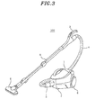
- the vacuum cleaner 100 includes a main body (canister body) 1 having a hose joint 3; a hose 4 connected to the main body 1 via the hose joint 3; an extension tube 5 provided with a handle 2 and connected to the hose 4 at one of its ends; and a suction head 6, installed at a free end of the extension tube 5, for the intake of dirt entraining air, whereby the main body 1 is in air flow communication with the suction head 6.
- the vacuum cleaner 100 further includes a caster 7 at a front bottom portion of the main body 1 and a pair of wheels 8 at both sides of a rear bottom portion thereof.
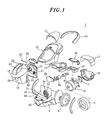
- the main body 1 has a lower body 9, an upper body 10 and a cover 11 defining the outline thereof in conjunction with each other.
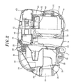
- An electric blower 12 for generating a suction air flow is fixedly installed at the lower body 9 with the help of a middle body 17, the front portion of the electric blower 12 being supported by a first support 13 made of, e.g., rubber and the rear portion thereof being supported by a first and a second motor cover 15 and 16 via a second support 14 made of, e.g., rubber.
- a dirt collecting case 18 has a case body 19 and a lid 21 detachably latched to the case body 19 by a shaft 20.
- the lid 21 is constructed in such a manner that it is released from the case body 19 by pushing a button 22 installed at top of the case body 19.
- the dirt collecting case 18 is detachably provided at an upstream of the suction air flow generated by the electric blower 12, i.e., at a recess 23 formed at a front portion of the lower body 9.
- the dirt collecting case 18 is further provided with a separation chamber 24 for centrifugally separating dirt from the dirt entraining air as will be described later, the separation chamber 24 generally being of a hollow cylindrical shape.
- the separation chamber 24 is in air flow communication with a dirt conveying conduit 26 for guiding the dirt containing air thereto via a second communication path 27; and also communicates with a dirt collecting chamber 29 for accumulating therein dirt separated from the dirt containing air via a first communication path 28.
- the dirt conveying conduit 26 is in air flow communication with a suction air inlet 25 of the main body 1 to guide the dirt containing air from the suction air inlet 25 to the separation chamber 24.
- the separation chamber 24 is provided with an air suction filter (or a first air intake member) 30 extending from the lid 21 and communicating with an air intake side of the electric blower 12.
- the second communication path 27 is located close to the air suction filter 30 and the first communication path 28 is disposed at a diagonal position with respect to the second communication path 27.
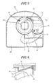
- a flow control guide 31 is provided at a position of the lid 21 corresponding to a portion of the dirt conveying conduit 26 next to the second communication path 27, for guiding the suction air flow toward the first communication path 28 along an inner wall of the separation chamber 24, as shown in Fig. 6.
- Adjacent to the first communication path 28 is installed a backflow barrier 32 for blocking a back stream of air from the dirt collecting chamber 29 to the separation chamber 24.
- the dirt collecting case 18 has compression filter (or a second air intake member) 33, and as shown in Figs. 4 and 5, the dirt collecting chamber 29 is in air flow communication with the air intake side of the electric blower 12 through a pre-filter 60 and the compression filter 33.
- the air suction filter 30 is in air flow communication with the electric blower 12 through a first air suction passage 35 having a first opening portion 34.
- the compression filter 33 is in air flow communication with the electric blower 12 via a second air suction passage 37 having a second opening portion 36.
- the first and the second opening portion 34, 36 respectively constituting the first and the second air suction passage 35, 37 are selectively blocked by a shielding plate 38.
- the shielding plate 38 is driven by the motor 40 which is mounted in a motor case 39 incorporating therein a reduction gear(not shown).
- the shielding plate 38 is coupled to the motor 40 via the reaction gear. Therefore, the shielding plate 38 can maintain its position even when the motor 40 is turned off. Normally(i.e., during time periods other than a predetermined time period after turning on the power of the vacuum cleaner 100), the shielding plate 38 is disposed at a position indicated by a dotted line shown in Fig.
- the shielding plate 38 is placed at a location indicated by one dotted chain line of Fig. 7, thereby blocking the first opening portion 34 constituting the first air suction passage 35 while opening the second opening portion 36 constituting the second air suction passage 37 for a preset time period.
- FIG. 8 there is shown a circuit diagram of a motor driving circuit having transistors Q1 to Q6. If a logic low(Lo) signal and a logic high(Hi) signal are respectively inputted to input terminals a and b for a preset time, e.g., 1.5 seconds, transistors Q1 to Q3 are turned to be “ON” and transistors Q4 to Q6 are turned to be “OFF”. Therefore, a voltage is applied to the motor 40 in a direction indicated by an arrow "A", making the motor 40 rotate in a normal direction, so that the first opening portion 34 constituting the first air suction passage 35 is blocked by the shielding plate 38.
- a logic low(Lo) signal and a logic high(Hi) signal are respectively inputted to input terminals a and b for a preset time, e.g., 1.5 seconds.
- the electric blower 12 While the first air suction passage 35 is blocked, the electric blower 12 is driven to operate at a maximum power level for the preset time period, e.g., 5 seconds. However, during a traveling time period of the shielding plate 38, e.g., 1.5 seconds, the electric blower 12 is driven to operate at a power level lower than the maximum power level.
- a reference numeral 41 represents a printed circuit board("PCB") including the motor driving circuit; 42, a PCB case for accommodating therein the PCB 41; and 43, a handle.
- PCB printed circuit board
- the hose joint 3 of the hose 4 is jointed to the suction air inlet 25 of the main body 1 and the other end of the hose 4 is connected to the suction head 6 via the extension tube 5.
- the electric blower 12 is driven at the operation power level lower than the maximum operation power level, and simultaneously, the Lo and Hi signals are applied to the terminals a and b for the preset time (1.5 seconds).
- the transistors Q1 to Q3 are turned “ON” and the transistors Q4 to Q6 are turned “OFF", so that the motor 40 rotates in the normal direction to rotate the shielding plate 38 to close the first opening portion 34 constituting the first air suction passage 35 and open the second opening portion 36 constituting the second air suction passage 37.
- the first opening portion 34 constituting the first air suction passage 35 is closed by the shielding plate 38; and then the motor 40 is turned “OFF” and the electric blower 12 starts to operate at the maximum operation power for the preset time period(5 seconds).
- the dirt containing air taken through the suction air inlet 25 is drawn to the electric blower 12, after passing through the dirt conveying conduit 26, the second communication path 27, the separation chamber 24, the first communication path 28, the dirt collecting chamber 29, the pre-filter 60, the compression filter 33, and the second air suction passage 37 having the second opening portion 36 in that order.
- the Lo and Hi signals are applied to the terminals b and a of the motor driving circuit for the predetermined time(1.5 seconds).
- This allows the transistors Q4 to Q6 to be turned “ON” and the transistors Q1 to Q3 to be turned “OFF”, thereby rotating the motor 40 in the reverse direction to return the shielding plate 38 to its initial position so as to open the first opening portion 34 constituting the first air suction passage 35 and to close the second opening portion 36 constituting the second air suction passage 37.
- the motor 40 is turned "OFF".
- the first communication path 28 is provided at the position diagonally opposite to the second communication path 27 of the separation chamber 24, and the flow control guide 31 for guiding the suction air toward the first communication path 28 along the inner wall of the separation chamber 24 is installed at the portion of the dirt conveying conduit 26 close to the second communication path 27, the dirt containing air drawn to the separation chamber 24 from the second communication path 27 can form a spiral air stream directing toward the first communication path 28 along the inner wall of the separation chamber 24.
- the shielding plate 38 is rotated by the motor 40 to close the first air suction passage 35 and open the second air suction passage 37 for the preset time period when the vacuum cleaner 100 starts to operate, it is possible to compress the dirt previously piled up in the dirt collecting chamber 29. As a result, premature degradation in the suction performance of the vacuum cleaner 100 due to a small amount of dirt can be effectively prevented. Moreover, since the need for removing dirt from the dirt collecting chamber 29 while operating the vacuum cleaner 100 becomes less likely, the efficiency of the vacuum cleaner 100 can be enhanced and at the same time, the inconvenience for frequent removal of the dirt from the dirt collecting chamber 29 can be avoided.
- the electric blower 12 is operated at the maximum operation power level when the first air suction passage 35 is closed, the amount of air taken through the suction head 6 can be maximized, which in turn allows the dirt accumulated in the dirt collecting chamber 29 to be compressed significantly.
- the shielding plate 38 is less affected by resistive force generated by the air stream pressure. Therefore, the conversion between the air suction passages 35 and 37 can be made smoothly.
- the shielding plate 38 is driven by the motor 40 during a certain period, the definite selection of the first or the second air suction passage 35 or 37 to be closed, i.e., the correct operation of the shielding plate 38 can be ensured.
- the inventive cleaner 100 may be provided with, e.g., a secondary battery(not shown) installed therein for providing the power enabling the vacuum cleaner 100 to compress the dirt, even in a case where a power plug thereof is pulled out, e.g., accidentally to stop the cleaner 100.
- a vacuum cleaner in accordance with a second preferred embodiment of the present invention will now be described with reference to Figs. 9 to 11.
- the vacuum cleaner of the second preferred embodiment is similar to the first one excepting for a shielding mechanism and opening portions associated therewith.
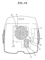
- the vacuum cleaner of the second preferred embodiment is provided with a first opening portion 44 constituting a first air suction passage(not shown) through which the air suction filter 30 (Fig. 1) is in air flow communication with the electric blower 12 (Fig. 1); and a second opening portion 45 constituting a second air suction passage(not shown) through which the compression filter 33(Fig. 1) is in air flow communication with the electric blower 12.
- the first and the second opening portion 44 and 45 respectively have a first and a second set of slots.
- the shielding plate 46 for selectively blocking the first and the second opening portion 44 and 45.
- the shielding plate 46 has a first and a second counterpart opening portion 47 and 48 corresponding to the first and the second opening portion 44 and 45, respectively.
- the first and the second opening counterpart portion 47 and 48 respectively have a first and a second group of counterpart slots having shapes similar to those of their corresponding slots of the opening portions 44 and 45.
- the first and the second counterpart slots are configured in such a manner that when the slots of one of the counterpart opening portions 47 and 48 are located to be aligned with those of a corresponding opening portion 44 or 45, the slots of the other one of the counterpart opening portions 47 and 48 are misaligned from those of the remaining opening portion 45 or 44 by, e.g., a width of one slot, as shown in Figs. 9 and 10.
- the shielding plate 46 is coupled to a coupling member 50 rotatably installed around a pivot 49 and can be shifted by the rotational movement of the coupling member 50 as much as a distance "d" as shown in Fig. 10.
- a solenoid 51 actuates the coupling member 50 via linear motion of a plunger 52.
- a coil 53 of the solenoid 51 is connected to an AC power source 55 via a bi-directional thyristor 54. If a logic high(Hi) signal is applied to an input terminal c, both of a transistor Q7 and the bi-directional thyristor 54 are turned “ON", to thereby induce a current through the coil 53 to allow the plunger 52 to be protruded and urge the shielding plate 46 to move by the distance "d" corresponding to the width of one slot as shown in Fig. 10.
- the parts of the vacuum cleaner other than the shielding mechanism described above in accordance with the second preferred embodiment are identical to those of the first preferred embodiment.
- the electric blower 12 is activated at an operation power level lower than the maximum operation power level and, simultaneously, the Hi signal is inputted to the input terminal c of the solenoid driving circuit. Consequently, both of the transistor Q7 and the bi-directional thyristor 54 are turned “ON”, thereby inducing a current to flow through the coil 53.
- the plunger 52 picks out and moves the shielding plate 46 by the distance "d" corresponding to the width of one slot, as shown in Fig. 10.
- the slots of the first counterpart opening portion 47 and those of the first opening portion 44 are alternately disposed without being overlapped with each other, while the slots of the second counterpart opening portion 48 are aligned with those of the second opening portion 45. Therefore, the first opening portion 44 is blocked by the shielding plate 46 while the second opening portion 45 is opened. Under this condition, the electric blower 12 is operated at the maximum operation power level and, therefore, the suction air drawn through the suction air inlet 25 can be used in compressing the dirt accumulated in the dirt collecting chamber 29 via the path identical to that described in the first preferred embodiment.
- the dirt containing air is revolved along the inner wall of the separation chamber 24 toward the first communication path 28 to form the cyclonic air flow. Owing to this cyclonic air flow, the dirt entrained in the suction air is centrifugally separated therefrom. Thus separated dirt is then accumulated in the dirt collecting chamber 29 and the remaining clean air is taken to the electric blower 12 via the air suction filter 30 and the first air suction passage having the first opening portion 44.
- the first and the second opening portion 44 and 45 can be selectively blocked by the shielding plate 46 driven by the solenoid 51, it is possible to centrifugally separate dirt from the suction air drawn through the suction head 6 for the collection thereof or compress thus collected dirt.
Landscapes
- Engineering & Computer Science (AREA)
- Mechanical Engineering (AREA)
- Filters For Electric Vacuum Cleaners (AREA)
- Nozzles For Electric Vacuum Cleaners (AREA)
Applications Claiming Priority (4)
| Application Number | Priority Date | Filing Date | Title |
|---|---|---|---|
| JP2001240795A JP3365410B1 (ja) | 2001-08-08 | 2001-08-08 | 電気掃除機 |
| JP2001240795 | 2001-08-08 | ||
| JP2001396423 | 2001-12-27 | ||
| JP2001396423A JP2003190059A (ja) | 2001-12-27 | 2001-12-27 | 電気掃除機 |
Publications (3)
| Publication Number | Publication Date |
|---|---|
| EP1283021A2 true EP1283021A2 (de) | 2003-02-12 |
| EP1283021A3 EP1283021A3 (de) | 2003-11-19 |
| EP1283021B1 EP1283021B1 (de) | 2010-09-22 |
Family
ID=26620189
Family Applications (1)
| Application Number | Title | Priority Date | Filing Date |
|---|---|---|---|
| EP02016767A Expired - Lifetime EP1283021B1 (de) | 2001-08-08 | 2002-07-26 | Staubsauger mit Staubverdichtungsmitteln |
Country Status (4)
| Country | Link |
|---|---|
| US (1) | US7047593B2 (de) |
| EP (1) | EP1283021B1 (de) |
| CN (1) | CN1247147C (de) |
| DE (1) | DE60237744D1 (de) |
Cited By (4)
| Publication number | Priority date | Publication date | Assignee | Title |
|---|---|---|---|---|
| GB2416112A (en) * | 2004-07-16 | 2006-01-18 | Lg Electronics Inc | Vacuum cleaner with dust compression facility |
| EP1690487A1 (de) * | 2005-02-15 | 2006-08-16 | Vax Limited | Zyklonstaubabscheider und Staubsammler für einen Staubsauger |
| EP1929917A2 (de) | 2004-12-14 | 2008-06-11 | LG Electronics Inc. | Staubsauger |
| EP1985373A3 (de) * | 2006-02-24 | 2011-04-20 | LG Electronics Inc. | Staubsammler für einen Staubsauger |
Families Citing this family (43)
| Publication number | Priority date | Publication date | Assignee | Title |
|---|---|---|---|---|
| GB2355391A (en) * | 1999-10-20 | 2001-04-25 | Notetry Ltd | Cyclonic vacuum cleaner with a horizontal, or substantially horizontal, separator |
| US6558453B2 (en) * | 2000-01-14 | 2003-05-06 | White Consolidated Industries, Inc. | Bagless dustcup |
| KR100485714B1 (ko) * | 2003-04-04 | 2005-04-28 | 삼성광주전자 주식회사 | 백레스 진공청소기 |
| US7152272B2 (en) * | 2003-07-14 | 2006-12-26 | Royal Appliance Mfg. Co. | On-board vehicle vacuum cleaner |
| US7712182B2 (en) * | 2003-07-25 | 2010-05-11 | Milwaukee Electric Tool Corporation | Air flow-producing device, such as a vacuum cleaner or a blower |
| CN100512740C (zh) * | 2004-04-07 | 2009-07-15 | 东芝泰格株式会社 | 电动吸尘器 |
| US7179062B1 (en) * | 2005-10-21 | 2007-02-20 | Drevitson Kyle C | Integrated shop vacuum and air compressor system |
| US20070163073A1 (en) * | 2006-01-19 | 2007-07-19 | Arnold Sepke | Vacuum cleaner dustcup and conduit construction |
| US20070174993A1 (en) * | 2006-02-02 | 2007-08-02 | Dever Kerry L | Filter cleaning system for floor cleaning apparatus |
| US7908707B2 (en) * | 2006-03-08 | 2011-03-22 | Panasonic Corporation Of North America | Floor cleaning apparatus with filter cleaning system |
| JP4709680B2 (ja) * | 2006-03-31 | 2011-06-22 | 株式会社東芝 | 電気掃除機 |
| USD561415S1 (en) * | 2006-05-02 | 2008-02-05 | Hoover Limited | Wand assembly for a vacuum cleaner |
| US7581287B2 (en) * | 2006-06-14 | 2009-09-01 | Panasonic Corporation Of North America | Vacuum cleaner with spiral air guide |
| US12220099B2 (en) | 2006-12-12 | 2025-02-11 | Omachron Intellectual Property Inc. | Surface cleaning apparatus |
| US12048409B2 (en) | 2007-03-11 | 2024-07-30 | Omachron Intellectual Property Inc. | Portable surface cleaning apparatus |
| US11751733B2 (en) | 2007-08-29 | 2023-09-12 | Omachron Intellectual Property Inc. | Portable surface cleaning apparatus |
| US20080264015A1 (en) * | 2007-04-30 | 2008-10-30 | Samsung Gwangju Electronics Co., Ltd | Dust compressing apparatus of vacuum cleaner |
| US7785381B2 (en) * | 2007-04-30 | 2010-08-31 | Samsung Gwangju Electronics Co., Ltd. | Dust collecting apparatus with combined compacting and filter cleaning for a vacuum cleaner |
| US20080264014A1 (en) * | 2007-04-30 | 2008-10-30 | Samsung Gwangju Electronics Co. Ltd. | Dust compressing apparatus of vacuum cleaner |
| US9591952B2 (en) | 2009-03-11 | 2017-03-14 | Omachron Intellectual Property Inc. | Hand vacuum cleaner with removable dirt chamber |
| CA2917900C (en) | 2009-03-13 | 2019-01-08 | Omachron Intellectual Property Inc. | Portable surface cleaning apparatus |
| US11690489B2 (en) | 2009-03-13 | 2023-07-04 | Omachron Intellectual Property Inc. | Surface cleaning apparatus with an external dirt chamber |
| US9211044B2 (en) | 2011-03-04 | 2015-12-15 | Omachron Intellectual Property Inc. | Compact surface cleaning apparatus |
| US9138114B2 (en) | 2009-03-13 | 2015-09-22 | Omachron Intellectual Property Inc. | Surface cleaning apparatus |
| US8601641B2 (en) | 2011-03-04 | 2013-12-10 | G.B.D. Corp. | Removable cyclone chamber and dirt collection assembly for a surface cleaning apparatus |
| US8683644B2 (en) | 2011-03-04 | 2014-04-01 | G.B.D. | Automatic cord release |
| US9232881B2 (en) * | 2011-03-04 | 2016-01-12 | Omachron Intellectual Property Inc. | Surface cleaning apparatus with removable handle assembly |
| US8689395B2 (en) * | 2011-03-04 | 2014-04-08 | G.B.D. Corp. | Portable surface cleaning apparatus |
| US8646146B2 (en) | 2011-03-04 | 2014-02-11 | G.B.D. Corp. | Suction hose wrap for a surface cleaning apparatus |
| EP2886031B1 (de) * | 2012-08-15 | 2018-12-26 | Mitsubishi Electric Corporation | Zyklontrennungsvorrichtung und elektrischer staubsauger damit |
| US10441125B2 (en) | 2016-08-29 | 2019-10-15 | Omachron Intellectual Property Inc. | Surface cleaning apparatus |
| US10433689B2 (en) | 2016-08-29 | 2019-10-08 | Omachron Intellectual Property Inc. | Surface cleaning apparatus |
| US10413141B2 (en) | 2016-08-29 | 2019-09-17 | Omachron Intellectual Property Inc. | Surface cleaning apparatus |
| US10441124B2 (en) | 2016-08-29 | 2019-10-15 | Omachron Intellectual Property Inc. | Surface cleaning apparatus |
| US10729295B2 (en) | 2016-08-29 | 2020-08-04 | Omachron Intellectual Property Inc. | Surface cleaning apparatus |
| US10292550B2 (en) | 2016-08-29 | 2019-05-21 | Omachron Intellectual Property Inc. | Surface cleaning apparatus |
| US10321794B2 (en) | 2016-08-29 | 2019-06-18 | Omachron Intellectual Property Inc. | Surface cleaning apparatus |
| US10136779B2 (en) | 2016-08-29 | 2018-11-27 | Omachron Intellectual Property Inc. | Surface cleaning apparatus |
| US9962050B2 (en) | 2016-08-29 | 2018-05-08 | Omachron Intellectual Property Inc. | Surface cleaning apparatus |
| US10405711B2 (en) | 2016-08-29 | 2019-09-10 | Omachron Intellectual Property Inc. | Surface cleaning apparatus |
| US10136780B2 (en) | 2016-08-29 | 2018-11-27 | Omachron Intellectual Property Inc. | Surface cleaning apparatus |
| US11478117B2 (en) | 2016-08-29 | 2022-10-25 | Omachron Intellectual Property Inc. | Surface cleaning apparatus |
| CN110063684B (zh) * | 2018-01-22 | 2025-10-14 | 天佑电器(苏州)有限公司 | 吸尘器 |
Citations (2)
| Publication number | Priority date | Publication date | Assignee | Title |
|---|---|---|---|---|
| JPH04370030A (ja) | 1991-06-14 | 1992-12-22 | Kubota Corp | 脱穀装置の除塵構造 |
| EP1136028A2 (de) | 2000-03-24 | 2001-09-26 | Sharp Kabushiki Kaisha | Elektrischer Staubsauger |
Family Cites Families (5)
| Publication number | Priority date | Publication date | Assignee | Title |
|---|---|---|---|---|
| US5254147A (en) * | 1990-04-03 | 1993-10-19 | Nutone, Inc. | Draw-down cyclonic vaccum cleaner |
| JP3158044B2 (ja) * | 1996-03-25 | 2001-04-23 | シャープ株式会社 | サイクロン式湿式電気掃除機 |
| US6003196A (en) * | 1998-01-09 | 1999-12-21 | Royal Appliance Mfg. Co. | Upright vacuum cleaner with cyclonic airflow |
| JP3530436B2 (ja) * | 1999-01-29 | 2004-05-24 | 三洋電機株式会社 | 掃除機用集塵装置及びアップライト型掃除機 |
| SE518257C2 (sv) * | 2001-01-11 | 2002-09-17 | Electrolux Ab | Anordning vid en dammsugare |
-
2002
- 2002-07-26 DE DE60237744T patent/DE60237744D1/de not_active Expired - Lifetime
- 2002-07-26 EP EP02016767A patent/EP1283021B1/de not_active Expired - Lifetime
- 2002-08-07 CN CNB021276765A patent/CN1247147C/zh not_active Expired - Fee Related
- 2002-08-08 US US10/214,203 patent/US7047593B2/en not_active Expired - Fee Related
Patent Citations (2)
| Publication number | Priority date | Publication date | Assignee | Title |
|---|---|---|---|---|
| JPH04370030A (ja) | 1991-06-14 | 1992-12-22 | Kubota Corp | 脱穀装置の除塵構造 |
| EP1136028A2 (de) | 2000-03-24 | 2001-09-26 | Sharp Kabushiki Kaisha | Elektrischer Staubsauger |
Cited By (14)
| Publication number | Priority date | Publication date | Assignee | Title |
|---|---|---|---|---|
| GB2416112A (en) * | 2004-07-16 | 2006-01-18 | Lg Electronics Inc | Vacuum cleaner with dust compression facility |
| US7647672B2 (en) | 2004-07-16 | 2010-01-19 | Lg Electronics Inc. | Vacuum cleaner |
| GB2416112B (en) * | 2004-07-16 | 2006-09-27 | Lg Electronics Inc | Vacuum cleaner |
| US7481868B2 (en) | 2004-12-14 | 2009-01-27 | Lg Electronics Inc. | Dust compressing apparatus and method for dust collecting unit of vacuum cleaner |
| EP1929917A3 (de) * | 2004-12-14 | 2008-10-15 | LG Electronics Inc. | Staubsauger |
| EP1929916A3 (de) * | 2004-12-14 | 2008-10-15 | LG Electronics, Inc. | Staubsauger |
| EP1929917A2 (de) | 2004-12-14 | 2008-06-11 | LG Electronics Inc. | Staubsauger |
| US7510587B2 (en) | 2004-12-14 | 2009-03-31 | Lg Electronics Inc. | Vacuum cleaner |
| US7600293B2 (en) | 2004-12-14 | 2009-10-13 | Lg Electronics Inc. | Vacuum cleaner |
| CN100455249C (zh) * | 2005-02-15 | 2009-01-28 | 瓦克瑟有限公司 | 用于吸尘器上的气旋分离器 |
| EP1690487A1 (de) * | 2005-02-15 | 2006-08-16 | Vax Limited | Zyklonstaubabscheider und Staubsammler für einen Staubsauger |
| RU2401046C2 (ru) * | 2005-02-15 | 2010-10-10 | Вэкс Лимитид | Циклонный сепаратор для мусороуборочной машины вакуумного действия |
| AU2005229774B2 (en) * | 2005-02-15 | 2011-05-12 | Vax Limited | Twin cyclone dust box |
| EP1985373A3 (de) * | 2006-02-24 | 2011-04-20 | LG Electronics Inc. | Staubsammler für einen Staubsauger |
Also Published As
| Publication number | Publication date |
|---|---|
| EP1283021B1 (de) | 2010-09-22 |
| CN1247147C (zh) | 2006-03-29 |
| US7047593B2 (en) | 2006-05-23 |
| EP1283021A3 (de) | 2003-11-19 |
| US20030028994A1 (en) | 2003-02-13 |
| CN1401291A (zh) | 2003-03-12 |
| DE60237744D1 (de) | 2010-11-04 |
Similar Documents
| Publication | Publication Date | Title |
|---|---|---|
| EP1283021B1 (de) | Staubsauger mit Staubverdichtungsmitteln | |
| US7600293B2 (en) | Vacuum cleaner | |
| EP1629758B1 (de) | Staubsammelanordnung für einen Staubsauger | |
| KR100398684B1 (ko) | 진공청소기의 사이클론 집진장치 | |
| US8726459B2 (en) | Vacuum cleaner | |
| KR100932760B1 (ko) | 진공청소기의 집진어셈블리 | |
| CN113271831B (zh) | 集尘装置和具有集尘装置的吸尘器 | |
| CN108065862A (zh) | 真空清洁器 | |
| CN1321608C (zh) | 吸入式吸尘器 | |
| TW201103484A (en) | Electric vacuum cleaner | |
| KR20090067309A (ko) | 진공 청소기의 집진 장치 | |
| TWI825605B (zh) | 清掃機 | |
| KR100411432B1 (ko) | 합체형 진공 청소기 | |
| CN109996480A (zh) | 电动吸尘器 | |
| KR20230015566A (ko) | 집진장치 및 이를 갖는 청소기 | |
| KR102689932B1 (ko) | 청소기 | |
| KR0138548B1 (ko) | 진공청소기의 집진실 위치변경 구조 | |
| US20260114680A1 (en) | Vacuum cleaner | |
| KR101199662B1 (ko) | 진공청소기의 집진유니트 | |
| KR20250103537A (ko) | 청소기와 청소기 스테이션 및 청소기 시스템 | |
| KR20240168188A (ko) | 청소기 | |
| JP2003190059A (ja) | 電気掃除機 | |
| KR200144975Y1 (ko) | 진공청소기용 필터의 설치구조 | |
| JP5258439B2 (ja) | 電気掃除機 | |
| CN110035682A (zh) | 电动吸尘器 |
Legal Events
| Date | Code | Title | Description |
|---|---|---|---|
| PUAI | Public reference made under article 153(3) epc to a published international application that has entered the european phase |
Free format text: ORIGINAL CODE: 0009012 |
|
| AK | Designated contracting states |
Designated state(s): AT BE BG CH CY CZ DE DK EE ES FI FR GB GR IE IT LI LU MC NL PT SE SK TR |
|
| AX | Request for extension of the european patent |
Extension state: AL LT LV MK RO SI |
|
| PUAL | Search report despatched |
Free format text: ORIGINAL CODE: 0009013 |
|
| AK | Designated contracting states |
Kind code of ref document: A3 Designated state(s): AT BE BG CH CY CZ DE DK EE ES FI FR GB GR IE IT LI LU MC NL PT SE SK TR |
|
| AX | Request for extension of the european patent |
Extension state: AL LT LV MK RO SI |
|
| 17P | Request for examination filed |
Effective date: 20040422 |
|
| AKX | Designation fees paid |
Designated state(s): DE GB |
|
| RAP1 | Party data changed (applicant data changed or rights of an application transferred) |
Owner name: PANASONIC CORPORATION |
|
| 17Q | First examination report despatched |
Effective date: 20091123 |
|
| GRAP | Despatch of communication of intention to grant a patent |
Free format text: ORIGINAL CODE: EPIDOSNIGR1 |
|
| GRAS | Grant fee paid |
Free format text: ORIGINAL CODE: EPIDOSNIGR3 |
|
| GRAA | (expected) grant |
Free format text: ORIGINAL CODE: 0009210 |
|
| AK | Designated contracting states |
Kind code of ref document: B1 Designated state(s): DE GB |
|
| REG | Reference to a national code |
Ref country code: GB Ref legal event code: FG4D |
|
| REF | Corresponds to: |
Ref document number: 60237744 Country of ref document: DE Date of ref document: 20101104 Kind code of ref document: P |
|
| PLBE | No opposition filed within time limit |
Free format text: ORIGINAL CODE: 0009261 |
|
| STAA | Information on the status of an ep patent application or granted ep patent |
Free format text: STATUS: NO OPPOSITION FILED WITHIN TIME LIMIT |
|
| 26N | No opposition filed |
Effective date: 20110623 |
|
| REG | Reference to a national code |
Ref country code: DE Ref legal event code: R097 Ref document number: 60237744 Country of ref document: DE Effective date: 20110623 |
|
| PGFP | Annual fee paid to national office [announced via postgrant information from national office to epo] |
Ref country code: DE Payment date: 20110720 Year of fee payment: 10 Ref country code: GB Payment date: 20110720 Year of fee payment: 10 |
|
| GBPC | Gb: european patent ceased through non-payment of renewal fee |
Effective date: 20120726 |
|
| PG25 | Lapsed in a contracting state [announced via postgrant information from national office to epo] |
Ref country code: GB Free format text: LAPSE BECAUSE OF NON-PAYMENT OF DUE FEES Effective date: 20120726 Ref country code: DE Free format text: LAPSE BECAUSE OF NON-PAYMENT OF DUE FEES Effective date: 20130201 |
|
| REG | Reference to a national code |
Ref country code: DE Ref legal event code: R119 Ref document number: 60237744 Country of ref document: DE Effective date: 20130201 |