EP1283080B1 - Biegevorrichtung und ihr Kontrollverfahren - Google Patents
Biegevorrichtung und ihr Kontrollverfahren Download PDFInfo
- Publication number
- EP1283080B1 EP1283080B1 EP02017866A EP02017866A EP1283080B1 EP 1283080 B1 EP1283080 B1 EP 1283080B1 EP 02017866 A EP02017866 A EP 02017866A EP 02017866 A EP02017866 A EP 02017866A EP 1283080 B1 EP1283080 B1 EP 1283080B1
- Authority
- EP
- European Patent Office
- Prior art keywords
- bending
- jig
- spherical
- bending device
- positioning jig
- Prior art date
- Legal status (The legal status is an assumption and is not a legal conclusion. Google has not performed a legal analysis and makes no representation as to the accuracy of the status listed.)
- Expired - Lifetime
Links
Images




Classifications
-
- B—PERFORMING OPERATIONS; TRANSPORTING
- B21—MECHANICAL METAL-WORKING WITHOUT ESSENTIALLY REMOVING MATERIAL; PUNCHING METAL
- B21D—WORKING OR PROCESSING OF SHEET METAL OR METAL TUBES, RODS OR PROFILES WITHOUT ESSENTIALLY REMOVING MATERIAL; PUNCHING METAL
- B21D7/00—Bending rods, profiles, or tubes
- B21D7/12—Bending rods, profiles, or tubes with program control
-
- B—PERFORMING OPERATIONS; TRANSPORTING
- B21—MECHANICAL METAL-WORKING WITHOUT ESSENTIALLY REMOVING MATERIAL; PUNCHING METAL
- B21D—WORKING OR PROCESSING OF SHEET METAL OR METAL TUBES, RODS OR PROFILES WITHOUT ESSENTIALLY REMOVING MATERIAL; PUNCHING METAL
- B21D7/00—Bending rods, profiles, or tubes
- B21D7/02—Bending rods, profiles, or tubes over a stationary forming member; by use of a swinging forming member or abutment
- B21D7/022—Bending rods, profiles, or tubes over a stationary forming member; by use of a swinging forming member or abutment over a stationary forming member only
Definitions
- This invention relates to a bending device according to the preamble of claim 1 and a method of operating such a bending device as known from JP-A-04-197528 and JP-A-09-103825.
- a heretofore known bending device supplies an elongate material in the axial direction of the material, and comprises a positioning jig having a clearance opening formed therein for passing the elongate material, fixed to a device body, and a bending jig arranged at a position to which the material is supplied from the positioning jig.
- the bending jig is supported to move linearly to both vertical and horizontal directions orthogonal to the longitudinal direction of material, and the material is bent into a required shape by being moved on a plane orthogonal to the longitudinal direction of material.
- An object of the present invention is to provide a bending device, and a control method thereof, which is simply organized and can bend the material by moving a bending jig having a clearance opening formed therein for passing an elongate material.
- the present invention provides a bending device comprising the features of claim 1.
- part of the rotating member is formed into a spherical shell which is held slidably between a pair of spherical convex and concave members both fixed to the device body, and the positioning jig is attached to the spherical convex member.
- the rotating member is rotated by means of at least three linear drive mechanisms.
- Drive mechanisms using servo motors or hydraulic cylinders can be adopted as the linear drive mechanisms.
- the bending device constituted as such can prevent the bent material passed from the bending jig from interfering with the rotating member and the spherical convex and concave members.
- a bending device 25 shown in Fig. 1 mainly comprises linear drive mechanisms 34, 36, 38, a rotating member 24, and a bending jig 28.
- One end of each linear drive mechanism 34, 36, 38 is fixed to a device frame 12, and the other end of the same is coupled with the rotating member 24.
- the bending jig 28 is attached to the rotating member 24.
- the material 1 is an elongate material and, for example, made of titanium alloy.
- the material 1 is coiled around a not shown bobbin. After the material 1, reeled out from the bobbin, is straightened, it passes between a pair of rollers 4, 6 provided on a drive mechanism 2 to be supplied in the axial direction of the material 1.
- a positioning jig 10 having a clearance opening formed therein for guiding and passing the material 1 is provided.
- the positioning jig 10 is attached to a spherical convex member 14.
- the spherical convex member 14 is fixed to a stay 12a which is fixed to the device frame 12.
- the spherical convex member 14 has a spherical surface 16 formed therein, which is convex in the supply direction of the material 1.
- the spherical convex member 14 is arranged so that the center "a" of the spherical surface 16 is located on the axis of the material 1 passing through the positioning jig 10.
- a spherical concave member 20 is fixed to a stay 12b, as shown in Fig. 3.
- the stay 12b is fixed to the device frame 12.
- a convex spherical surface 22 is formed on a surface of the spherical concave member 20, opposite to the spherical surface 16 of the spherical convex member 14, a convex spherical surface 22 is formed.
- the spherical surface 22 is concentric to the spherical surface 16 and has the common center "a", as can be seen in Fig. 3.
- About one fourth of the spherical concave member 20 is also cut off just like the spherical convex member 14.
- a dome portion 26 which constitutes part of the rotating member 24 is held.
- the dome portion 26 is formed into a spherical shell having a certain thickness.
- a convex surface of the spherical shell-like dome portion 26 is concentric to the spherical surface 22, while a concave surface of the spherical shell-like dome portion 26 is concentric to the spherical surface 16. Accordingly, it is possible for the dome portion 26 to slide between the concave spherical surface 22 of the spherical concave member 20 and the convex spherical surface 16 of the spherical convex member 14.
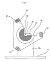
- the bending jig 28 is attached to a cut off area 32 of the dome portion 26.
- the bending jig 28 has a clearance opening 30 formed therein for passing the material 1.
- the three linear drive mechanisms 34, 36, 38 are arranged at an evenly spaced angle to be parallel to the axial direction of the material 1.
- the three linear drive mechanisms 34, 36, 38 are expandable and contractable. They can be, for example, drive mechanisms using hydraulic cylinders or servo motors.
- each linear drive mechanism 34, 36, 38 is coupled with the rotating member 24 via a ball joint 40, 42, 44, respectively, while the other end of the same is coupled with the device frame 12 via a universal joint 46, 48, 50, respectively.
- the linear drive mechanisms 34, 36, 38 are expanded and contracted to a direction approximately parallel to a moving direction of the material 1.
- a pair of rollers 4, 6 of the drive mechanism 2 are driven, and the material 1 is supplied from the drive mechanism 2 in the axial direction of the material 1.
- the material 1 passes through the clearance opening 8 of the positioning jig 10 then the clearance opening 30 of the bending jig 28.
- the linear drive mechanisms 34, 36, 38 are separately controlled for expansion or contraction, respectively, to rotate the rotating member 24.
- the bending jig 28 is freely moved along the spherical surfaces 16, 22 having the common center "a".
- the positioning jig 10 is fixed to the device frame 12, the bending jig 28 is moved along the spherical surfaces 16, 22, and the material 1 is supplied to be bent to the bending jig 28 with its supply direction changed.
- the bending jig 28 can be moved freely to any direction along the spherical surfaces 16, 22, it is possible to bend the material 1 into a required shape.
- the cut off area 32 of the dome portion 26 a cut off area of the spherical concave member 20 and the cut off area 18 of the spherical convex member 14 completely overlap with each other when looked from the axial direction of the material 1, as shown in Figs. 4 and 5, interference with the dome portion 26, spherical concave member 20 and spherical convex member 14 can be prevented when the bent material 1 is passed from the bending jig 28.
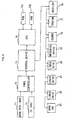
- Fig. 6 is a block diagram showing a functional constitution of the bending device of the present embodiment.
- types of the material 1 and the bending jig 28, etc. are selected to create a work data input 71 or a FD input 72.
- FD denotes, for example, an external memory such as a floppy disk.
- the work data input 71 or FD input 72 is inputted to a panel controller 73.
- An output from the panel controller 73 is inputted to a control device 74.
- a CPU 75 connected to the control device 74 necessary calculation is performed using, if required, an external memory 75a, ROM 75b and RAM 75c. A result of the calculation in the CPU 75 is again inputted to the control device 74.
- An output from the control device 74 is transmitted to an uncoiler 76 and the following operational portions as a command value. More particularly, the material 1 is reeled out from a bobbin by means of the uncoiler 76, and is straightened and stretched at a predetermined speed by means of a tension 77, to be supplied to the drive mechanism 2. The material 1 supplied from the drive mechanism 2 at a predetermined speed by means of a feeder 78 is measured by a measuring device 79 (encoder) and passed to the positioning jig 10. Then, three linear drive mechanisms, that is, linear drive mechanisms 80, 81 and 82, are expanded or contracted, to complete required bending. Lastly, the bent material 1 is cut up into respective product units in a work cut 83.
- Fig. 7 shows a control method of the bending device by means of a flowchart.
- a selection of a material is performed (S102) and then a selection of a bending jig is performed (S104).
- Results of the selections are inputted as a work data input (S106) to create work data (S108). If the work data input is incomplete, a process returns to the work data input (S106) till a correct work data input is made.
- a start switch is turned on (S110) and bending is performed (S112).
- the bent work piece is cut up into respective product units in the work cut (S114), and the process ends (S116). Steps from bending (S112) to the work cut (S114) are repeated until the number of bending inputted upon the work data input is completed.
- the bending device of the present invention has a simple mechanical structure which enables the bending jig to move along the spherical surface, and can freely bend the material at any direction.
- linear drive mechanisms For instance, three linear drive mechanisms are provided in the present embodiment. However, four or more linear drive mechanisms will enable bending by which further complicated shapes are attained.
- the linear drive mechanisms are arranged parallel to the axial direction of the material. However, they do not necessarily have to be so.
Landscapes
- Engineering & Computer Science (AREA)
- Mechanical Engineering (AREA)
- Bending Of Plates, Rods, And Pipes (AREA)
- Wire Processing (AREA)
Claims (7)
- Biegevorrichtung, umfassend:eine Positionierschablone (10) mit einer darin eingeformten Spielöffnung zum Durchlassen eines langgestreckten Werkstückes (1), wobei die Positionierschablone (10) an einem Vorrichtungsgehäuse fixiert ist;eine Biegeschablone (28) mit einer darin eingeformten Spielöffnung (30) zum Durchlassen des langgestreckten Werkstückes, wobei die Biegeschablone an einer Stelle angeordnet ist, zu der das Werkstück (1) von der Positionierschablone (10) zugeführt wird; undein Drehglied (24) zum Drehen der Biegeschablone (28) auf und entlang einer sphärischen Oberfläche (16, 22) mit einem Zentrum (a), das mit demjenigen des langgestreckten, die Positionierschablone passierenden Werkstückes (1) zusammenfällt, dadurch gekennzeichnet, daßein Abschnitt des Drehgliedes (24) als sphärische Schale (26) ausgebildet und gleitbar zwischen einem Paar sphärischer konvexer und konkaver Bauteile (14, 20) gehalten ist, die an dem Vorrichtungsgehäuse fixiert sind.
- Biegevorrichtung nach Anspruch 1, dadurch gekennzeichnet, daß die Positionierschablone (10) an dem konvexen sphärischen Bauteil (14) angebracht ist.
- Biegevorrichtung nach Anspruch 1 oder 2, dadurch gekennzeichnet, daß das Drehglied (24) mittels dreier Linear-Antriebe (34, 36, 38) gedreht wird.
- Biegevorrichtung nach Anspruch 3, dadurch gekennzeichnet, daß die Linear-Antriebe (34, 36, 38) hydraulische Zylinder oder Servomotoren verwenden.
- Biegevorrichtung nach einem der Ansprüche 1 bis 4, dadurch gekennzeichnet, daß ein Abschnitt des Drehgliedes abgeflacht ist.
- Biegevorrichtung nach einem der Ansprüche 1 bis 4, dadurch gekennzeichnet , daß jeweils ein Abschnitt der sphärischen konvexen und konkaven Bauteile (14, 20) abgeflacht ist.
- Verfahren zum Betreiben einer Biegevorrichtung nach einem der Ansprüche 1 bis 6, dadurch gekennzeichnet, daß ein Biegen dadurch bewerkstelligt wird, daß das langgestreckte Werkstück (1) mit sich ändernder Zuführrichtung aus der Positionierschablone (10) zur Biegeschablone (28) zugeführt wird, welche sich entlang der sphärischen Oberfläche (16, 22) bewegt.
Applications Claiming Priority (2)
| Application Number | Priority Date | Filing Date | Title |
|---|---|---|---|
| JP2001240615A JP4777553B2 (ja) | 2001-08-08 | 2001-08-08 | 曲げ加工装置 |
| JP2001240615 | 2001-08-08 |
Publications (3)
| Publication Number | Publication Date |
|---|---|
| EP1283080A2 EP1283080A2 (de) | 2003-02-12 |
| EP1283080A3 EP1283080A3 (de) | 2003-05-07 |
| EP1283080B1 true EP1283080B1 (de) | 2006-12-27 |
Family
ID=19071197
Family Applications (1)
| Application Number | Title | Priority Date | Filing Date |
|---|---|---|---|
| EP02017866A Expired - Lifetime EP1283080B1 (de) | 2001-08-08 | 2002-08-08 | Biegevorrichtung und ihr Kontrollverfahren |
Country Status (5)
| Country | Link |
|---|---|
| US (1) | US6725700B2 (de) |
| EP (1) | EP1283080B1 (de) |
| JP (1) | JP4777553B2 (de) |
| KR (1) | KR20030014585A (de) |
| DE (1) | DE60217025T2 (de) |
Cited By (2)
| Publication number | Priority date | Publication date | Assignee | Title |
|---|---|---|---|---|
| CN104550352A (zh) * | 2015-01-12 | 2015-04-29 | 常州市兴维邦精密机械制造有限公司 | 便捷式钢管折弯机 |
| CN111633078A (zh) * | 2020-06-17 | 2020-09-08 | 南京航空航天大学 | 一种超薄壁弯管旋弯成形方法及装置 |
Families Citing this family (5)
| Publication number | Priority date | Publication date | Assignee | Title |
|---|---|---|---|---|
| US8419111B2 (en) * | 2005-03-02 | 2013-04-16 | Nippon Steel & Sumitomo Metal Corporation | Vehicle body reinforcing member |
| JP4934283B2 (ja) * | 2005-03-02 | 2012-05-16 | 住友金属工業株式会社 | 車体補強用部材 |
| US8307685B2 (en) * | 2008-04-09 | 2012-11-13 | Shape Corp. | Multi-directionally swept beam, roll former, and method |
| US8333096B2 (en) * | 2009-09-21 | 2012-12-18 | Shape Corp. | Method of forming three-dimensional multi-plane beam |
| CN106311830B (zh) * | 2015-07-01 | 2020-04-10 | 山东交通职业学院 | 一种钢管变曲率半径弯曲方法及实现设备 |
Family Cites Families (13)
| Publication number | Priority date | Publication date | Assignee | Title |
|---|---|---|---|---|
| US3690278A (en) * | 1970-10-09 | 1972-09-12 | Printal Oy | Method and device for the manufacture of seamless metal bottles |
| DE2249994C2 (de) * | 1972-10-12 | 1974-03-07 | Th. Kieserling & Albrecht, 5650 Solingen | Zieh-Rieht-Vorrichtung für Stangen oder Rohre |
| US3952572A (en) | 1974-01-23 | 1976-04-27 | Case Western Reserve University | Beam bender |
| JPH01154824A (ja) | 1987-12-10 | 1989-06-16 | Chuo Electric Mfg Co Ltd | 曲げ装置 |
| JPH07110382B2 (ja) * | 1990-11-28 | 1995-11-29 | 日進精機株式会社 | 押し通し曲げ加工装置におけるダイス機構 |
| JP2951012B2 (ja) * | 1991-02-20 | 1999-09-20 | 昭和アルミニウム株式会社 | 曲げ加工装置 |
| JP2715397B2 (ja) | 1995-10-09 | 1998-02-18 | 日進精機株式会社 | 押し通し曲げ加工装置におけるダイス回動機構 |
| JPH09182918A (ja) * | 1995-12-28 | 1997-07-15 | Opton Co Ltd | ロール成形機 |
| JPH1024327A (ja) * | 1996-07-10 | 1998-01-27 | Opton Co Ltd | 曲げ加工装置 |
| JP3558487B2 (ja) * | 1997-05-15 | 2004-08-25 | 本田技研工業株式会社 | 長尺ワークの曲げ・捩り加工装置 |
| JP2000046140A (ja) * | 1998-07-31 | 2000-02-18 | Yaskawa Electric Corp | 電動シリンダおよびパラレルリンクロボット |
| DE19956796A1 (de) | 1999-11-25 | 2001-06-13 | Palima W Ludwig & Co | Biegevorrichtung für das 2- und 3-dimensionale Profilbiegen |
| JP4081593B2 (ja) * | 2001-05-18 | 2008-04-30 | 健 一柳 | 長尺材の曲げ加工装置 |
-
2001
- 2001-08-08 JP JP2001240615A patent/JP4777553B2/ja not_active Expired - Fee Related
-
2002
- 2002-08-01 KR KR1020020045538A patent/KR20030014585A/ko not_active Abandoned
- 2002-08-06 US US10/213,884 patent/US6725700B2/en not_active Expired - Fee Related
- 2002-08-08 DE DE60217025T patent/DE60217025T2/de not_active Expired - Fee Related
- 2002-08-08 EP EP02017866A patent/EP1283080B1/de not_active Expired - Lifetime
Cited By (3)
| Publication number | Priority date | Publication date | Assignee | Title |
|---|---|---|---|---|
| CN104550352A (zh) * | 2015-01-12 | 2015-04-29 | 常州市兴维邦精密机械制造有限公司 | 便捷式钢管折弯机 |
| CN111633078A (zh) * | 2020-06-17 | 2020-09-08 | 南京航空航天大学 | 一种超薄壁弯管旋弯成形方法及装置 |
| CN111633078B (zh) * | 2020-06-17 | 2021-05-25 | 南京航空航天大学 | 一种超薄壁弯管旋弯成形方法及装置 |
Also Published As
| Publication number | Publication date |
|---|---|
| EP1283080A2 (de) | 2003-02-12 |
| DE60217025D1 (de) | 2007-02-08 |
| JP2003053431A (ja) | 2003-02-26 |
| EP1283080A3 (de) | 2003-05-07 |
| US6725700B2 (en) | 2004-04-27 |
| US20030029213A1 (en) | 2003-02-13 |
| KR20030014585A (ko) | 2003-02-19 |
| JP4777553B2 (ja) | 2011-09-21 |
| DE60217025T2 (de) | 2007-07-19 |
Similar Documents
| Publication | Publication Date | Title |
|---|---|---|
| US8327679B2 (en) | Folding system for a cutting blade | |
| FI73616B (fi) | Anordning vid robotmanipulator. | |
| EP0025929A1 (de) | Verfahren zum Biegen eines Metallrohres | |
| US6301525B1 (en) | System and method for controlling a robot | |
| EP1283080B1 (de) | Biegevorrichtung und ihr Kontrollverfahren | |
| JPH089063B2 (ja) | パイプ自動ベンダーにおける曲げ加工ユニット装置 | |
| US5259226A (en) | Mechanism for forming spring pitch | |
| US4947670A (en) | Universal automatic spring-making machine | |
| US4090387A (en) | Bending-tool and a device fitted out with such a tool | |
| EP1042085B1 (de) | Verfahren und vorrichtung zur herstellung einer schnecke | |
| KR100574550B1 (ko) | 장척재의 굽힘 가공장치 | |
| KR101063267B1 (ko) | 굽힘 가공 장치 | |
| US5839312A (en) | Spring manufacturing apparatus | |
| US20050076694A1 (en) | Wire bending device | |
| US6260395B1 (en) | Vertically oriented apparatus for bending tubing, and method of using same | |
| US4312206A (en) | Making a seamless, spherical case | |
| KR920001596B1 (ko) | 세경 금속관의 굽힘 가공 장치 | |
| US20030010084A1 (en) | Wire bending device | |
| JP4972548B2 (ja) | アクチュエータ並びにこれを用いたパラレルリンク機構及び長尺材の曲げ加工装置 | |
| CA2081332A1 (en) | Device for delivering a collimated beam such as a laser beam | |
| US5660067A (en) | Versatile spring making machine | |
| US6688147B2 (en) | Panel curving machine | |
| US4961335A (en) | Small-diameter metallic conduit | |
| JP2534530B2 (ja) | スピニングマシンの絞り加工制御方法 | |
| JPH0140686B2 (de) |
Legal Events
| Date | Code | Title | Description |
|---|---|---|---|
| PUAI | Public reference made under article 153(3) epc to a published international application that has entered the european phase |
Free format text: ORIGINAL CODE: 0009012 |
|
| AK | Designated contracting states |
Designated state(s): AT BE BG CH CY CZ DE DK EE ES FI FR GB GR IE IT LI LU MC NL PT SE SK TR |
|
| AX | Request for extension of the european patent |
Extension state: AL LT LV MK RO SI |
|
| PUAL | Search report despatched |
Free format text: ORIGINAL CODE: 0009013 |
|
| AK | Designated contracting states |
Designated state(s): AT BE BG CH CY CZ DE DK EE ES FI FR GB GR IE IT LI LU MC NL PT SE SK TR |
|
| AX | Request for extension of the european patent |
Extension state: AL LT LV MK RO SI |
|
| 17P | Request for examination filed |
Effective date: 20031013 |
|
| AKX | Designation fees paid |
Designated state(s): DE FR GB IT |
|
| GRAP | Despatch of communication of intention to grant a patent |
Free format text: ORIGINAL CODE: EPIDOSNIGR1 |
|
| GRAS | Grant fee paid |
Free format text: ORIGINAL CODE: EPIDOSNIGR3 |
|
| GRAA | (expected) grant |
Free format text: ORIGINAL CODE: 0009210 |
|
| AK | Designated contracting states |
Kind code of ref document: B1 Designated state(s): DE FR GB IT |
|
| REG | Reference to a national code |
Ref country code: GB Ref legal event code: FG4D |
|
| REF | Corresponds to: |
Ref document number: 60217025 Country of ref document: DE Date of ref document: 20070208 Kind code of ref document: P |
|
| ET | Fr: translation filed | ||
| PLBE | No opposition filed within time limit |
Free format text: ORIGINAL CODE: 0009261 |
|
| STAA | Information on the status of an ep patent application or granted ep patent |
Free format text: STATUS: NO OPPOSITION FILED WITHIN TIME LIMIT |
|
| 26N | No opposition filed |
Effective date: 20070928 |
|
| PGFP | Annual fee paid to national office [announced via postgrant information from national office to epo] |
Ref country code: DE Payment date: 20080821 Year of fee payment: 7 |
|
| PGFP | Annual fee paid to national office [announced via postgrant information from national office to epo] |
Ref country code: FR Payment date: 20080818 Year of fee payment: 7 Ref country code: IT Payment date: 20080828 Year of fee payment: 7 |
|
| PGFP | Annual fee paid to national office [announced via postgrant information from national office to epo] |
Ref country code: GB Payment date: 20080820 Year of fee payment: 7 |
|
| GBPC | Gb: european patent ceased through non-payment of renewal fee |
Effective date: 20090808 |
|
| REG | Reference to a national code |
Ref country code: FR Ref legal event code: ST Effective date: 20100430 |
|
| PG25 | Lapsed in a contracting state [announced via postgrant information from national office to epo] |
Ref country code: DE Free format text: LAPSE BECAUSE OF NON-PAYMENT OF DUE FEES Effective date: 20100302 Ref country code: FR Free format text: LAPSE BECAUSE OF NON-PAYMENT OF DUE FEES Effective date: 20090831 |
|
| PG25 | Lapsed in a contracting state [announced via postgrant information from national office to epo] |
Ref country code: GB Free format text: LAPSE BECAUSE OF NON-PAYMENT OF DUE FEES Effective date: 20090808 |
|
| PG25 | Lapsed in a contracting state [announced via postgrant information from national office to epo] |
Ref country code: IT Free format text: LAPSE BECAUSE OF NON-PAYMENT OF DUE FEES Effective date: 20090808 |