EP1283116A2 - Gleitschutzvorrichtung für Kraftfahrzeugreifen - Google Patents
Gleitschutzvorrichtung für Kraftfahrzeugreifen Download PDFInfo
- Publication number
- EP1283116A2 EP1283116A2 EP02015404A EP02015404A EP1283116A2 EP 1283116 A2 EP1283116 A2 EP 1283116A2 EP 02015404 A EP02015404 A EP 02015404A EP 02015404 A EP02015404 A EP 02015404A EP 1283116 A2 EP1283116 A2 EP 1283116A2
- Authority
- EP
- European Patent Office
- Prior art keywords
- plate
- arms
- antiskid device
- bolt
- antiskid
- Prior art date
- Legal status (The legal status is an assumption and is not a legal conclusion. Google has not performed a legal analysis and makes no representation as to the accuracy of the status listed.)
- Granted
Links
- 125000006850 spacer group Chemical group 0.000 claims description 9
- 238000005520 cutting process Methods 0.000 claims description 2
- 230000002093 peripheral effect Effects 0.000 claims description 2
- 230000000903 blocking effect Effects 0.000 description 2
- 238000004519 manufacturing process Methods 0.000 description 2
- 238000010276 construction Methods 0.000 description 1
- 230000008878 coupling Effects 0.000 description 1
- 238000010168 coupling process Methods 0.000 description 1
- 238000005859 coupling reaction Methods 0.000 description 1
- 230000000694 effects Effects 0.000 description 1
- 239000002184 metal Substances 0.000 description 1
- 238000000034 method Methods 0.000 description 1
- 238000003860 storage Methods 0.000 description 1
- 238000005303 weighing Methods 0.000 description 1
Images



Classifications
-
- B—PERFORMING OPERATIONS; TRANSPORTING
- B60—VEHICLES IN GENERAL
- B60C—VEHICLE TYRES; TYRE INFLATION; TYRE CHANGING; CONNECTING VALVES TO INFLATABLE ELASTIC BODIES IN GENERAL; DEVICES OR ARRANGEMENTS RELATED TO TYRES
- B60C27/00—Non-skid devices temporarily attachable to resilient tyres or resiliently-tyred wheels
- B60C27/02—Non-skid devices temporarily attachable to resilient tyres or resiliently-tyred wheels extending over restricted arcuate part of tread
-
- B—PERFORMING OPERATIONS; TRANSPORTING
- B60—VEHICLES IN GENERAL
- B60C—VEHICLE TYRES; TYRE INFLATION; TYRE CHANGING; CONNECTING VALVES TO INFLATABLE ELASTIC BODIES IN GENERAL; DEVICES OR ARRANGEMENTS RELATED TO TYRES
- B60C27/00—Non-skid devices temporarily attachable to resilient tyres or resiliently-tyred wheels
- B60C27/02—Non-skid devices temporarily attachable to resilient tyres or resiliently-tyred wheels extending over restricted arcuate part of tread
- B60C27/023—Non-skid devices temporarily attachable to resilient tyres or resiliently-tyred wheels extending over restricted arcuate part of tread provided with radial arms for supporting the ground engaging parts on the wheel
-
- B—PERFORMING OPERATIONS; TRANSPORTING
- B60—VEHICLES IN GENERAL
- B60C—VEHICLE TYRES; TYRE INFLATION; TYRE CHANGING; CONNECTING VALVES TO INFLATABLE ELASTIC BODIES IN GENERAL; DEVICES OR ARRANGEMENTS RELATED TO TYRES
- B60C27/00—Non-skid devices temporarily attachable to resilient tyres or resiliently-tyred wheels
- B60C27/02—Non-skid devices temporarily attachable to resilient tyres or resiliently-tyred wheels extending over restricted arcuate part of tread
- B60C27/0261—Non-skid devices temporarily attachable to resilient tyres or resiliently-tyred wheels extending over restricted arcuate part of tread provided with fastening means
- B60C27/0269—Non-skid devices temporarily attachable to resilient tyres or resiliently-tyred wheels extending over restricted arcuate part of tread provided with fastening means acting on the wheel, e.g. on the rim or wheel bolts
-
- B—PERFORMING OPERATIONS; TRANSPORTING
- B60—VEHICLES IN GENERAL
- B60C—VEHICLE TYRES; TYRE INFLATION; TYRE CHANGING; CONNECTING VALVES TO INFLATABLE ELASTIC BODIES IN GENERAL; DEVICES OR ARRANGEMENTS RELATED TO TYRES
- B60C27/00—Non-skid devices temporarily attachable to resilient tyres or resiliently-tyred wheels
- B60C27/02—Non-skid devices temporarily attachable to resilient tyres or resiliently-tyred wheels extending over restricted arcuate part of tread
- B60C27/04—Non-skid devices temporarily attachable to resilient tyres or resiliently-tyred wheels extending over restricted arcuate part of tread the ground-engaging part being rigid
Definitions
- the object of the present invention is an antiskid device for vehicle wheels of the type suitable to be used particularly in presence of snow and/or ice for increasing the grip of the tire against the surface covered by the wheel during the vehicle ride.
- the currently known antiskid devices can be subdivided into antiskid devices without parts permanently connected to the vehicle wheel and antiskid devices with parts permanently connected to the vehicle wheel.
- the first group of antiskid devices generally comprises the snow chains that are integrally mounted when necessary, that is when conditions of roadbed covered in snow or ice occur on the vehicle wheel.
- the devices of this group are provided with means for the direct fixing to the vehicle wheel.
- the second group of antiskid devices comprises devices separated in two or more parts, at least one of which being fixed to the vehicle wheel in a permanent way, for instance when the winter season begins, in order to allow a more rapid assembly of the remaining parts.
- the present invention concerns said second type of antiskid devices.
- a device of this type is described for instance in the document EP 0 397 067.
- a disadvantage of the known devices is due to the impossibility of adjusting the radial opening of the arms so that it is consequently necessary to produce a high number of different sizes for the different types of wheels and tires on the market.
- a first object of the present invention is to provide an appropriate solution to the problem of how to avoid the construction of antiskid devices of the above mentioned type having different sizes, in order to adapt said devices to all the wheels and the tires under production.
- a disadvantage of the devices of the above mentioned type derives from the dimensions of the device.
- the dimensions of the devices of the second group can not be reduced and this causes an increase of the transport and storage costs.
- a second object of the present invention is that of getting round the known disadvantages by providing an antiskid device of the above mentioned second group that can be adapted to a vast range of sizes of vehicle wheels and tires.
- a further problem that can be met in the antiskid devices of the second type derives from the need of allowing a rapid assembly and disassembly of the device with respect to the part that remains permanently fixed to the vehicle wheel.
- the device is equipped with a coupling allowing the reciprocal engagement of teeth provided on the two parts.
- a snap rotating element allows to block the reciprocal movement between the two parts and, consequently, to avoid the disengagement between the teeth.
- a further object of the present invention is that of providing an antiskid device provided with economical and reliable means for allowing a rapid assembly and disassembly.
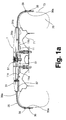
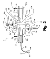
- an antiskid device 1 comprising a first plate 11, preferably realised in metal, for fixing the device 1 against the rim 71 of the vehicle wheel and a second plate 31, preferably realised in plastic, that can be coupled to said first plate 11 through rapid fixing means 51.
- the first plate 11 comprises a substantially smooth central portion 11a and a peripheral returned edge 11b for defining a supporting surface 11c for the second plate 31.
- the central portion 11a of the plate 11 comprises a series of holes 13 for the passage of bolts 15 engaging in threaded seats 17a internally provided to spacers 17, said spacers being screwed, in turn, on the threaded portion 19a of the hexagon nuts 19 that co-operate with the studs 21 for fixing the rim 71 into the wheel hub of the vehicle.
- the holes 13 are preferably realised under form of slots arranged along the spokes of the plate 11 and in such a number and distributed on the central portion 11a in such a way to allow the fixing of the plate 11 against whatever wheel rim in the market.
- the second plate 31 results to be subdivided into two shells 31a and 31b held together by bolts 33a passing through holes 41 provided through the shells 31a and 31b and corresponding nuts 33b.
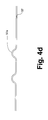
- the arms 35, sunburst-arranged and provided with an end 35a folded at approximately 90°, are housed between the shells 31a and 31b.
- some triangular projections 31c tapered towards the centre of the plate 31, are obtained on the second plate 31.
- the projections 31c separate the arms 35, allow the orientation of the arms for making the assembly easier and allow their adjustment under the weight of the vehicle during the use.
- the arms 35 are folded in order to overlap at least on a portion of the tread 73 of the vehicle tire 75 when the device 1 is mounted.
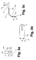
- spikes 39 are provided on the folded end 35a of the arms 35 for increasing the grip of the device with respect to the ground surface covered by the vehicle wheel during the ride.
- the spike heads 39 present a pair of perpendicular grooves 39a defining corresponding cutting edges for increasing the grip, in particular against the iced surfaces.
- portion 35a is subdivided into two halves by a slit 45 presenting a triangular, outwardly countersunk, more external portion 45a and an internal substantially rectangular portion 45b.
- This expedient aims to allow the expansion of the two halves of the portion 35a and to grant a better grip of the device against the ground.
- the straight part 35b of the arms 35 presents a slot 37 for the passage of the bolts 33a for allowing the radial adjustment of the arms 35 and the consequent amplitude adjustment of the device 1 for adapting said device 1 to different sizes of tires, although the possibility of angular orientation is kept limited by the projections 31c.
- the device according to the invention can be advantageously equipped for its commercialisation with some series of spacers 43 of different sizes that the user will mount on the device according to the wheel diameter of his/her own vehicle.
- the folded ends of the arms 35 are provided with teeth 35c on the side turned towards the tread for increasing the grip against the tire and reducing the relative movements between an arm and the tire during the vehicle ride.
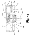
- the first shell 31a is centrally provided with a circular opening 47a preceded towards the exterior by a circular seat 47b where the rapid fixing means 51 are housed.
- the fixing means 51 comprise a knob or handwheel 53 provided with a central hexagon hole 53a through which the hexagon stem 55a of a bolt 55 passes so that the bolt 55 rotates together with the knob 53.
- the stem 55a of said bolt 55 presents a terminal threaded portion 55b engaging in a threaded bushing 23 centrally welded in the first plate 11 for fixing the second plate 31 against the first plate 11 when the device 1 must be used.
- a ring nut 57 is provided between the knob 53 and the shoulder 47c defined between the opening 47a and the seat 47b, said ring nut 57 being equipped with radial peripherally spaced bosses that interfere with corresponding projections 53b obtained on the lower part of the knob 53 .
- a helical spring 59 is provided in the knob 53 between the bolt head 55 and the seat 53c for the bolt, and an elastic ring 55c is provided inserted into a circumferential groove 55d of the bolt 55 for holding together the bolt 55, the spring 59, the knob 53 and the ring nut 57.
- the ring nut 57 presents a lower region that acts as a shoulder for the stem 55a of the bolt 55 when the latter is completely tightened.
- the ring nut 57 is provided with holes 57b in which pins 25 are inserted, said pins extending axially from the surface 11a of the first plate 11 and preventing the rotation of the ring nut 57 with respect to the first plate 11, thereby allowing the engagement between the projections 53b and the bosses 57a when the knob 53 is tightened.
- the wheel hub of the vehicle is first arranged for receiving the device 1 by mounting the nuts 19 into the studs 21.
- the nuts 19 can be directly screwed on the studs with which the hub is already equipped, or on the studs equipped with the device, said studs being screwed into the threaded holes provided in the hub.
- the first plate 11 can be fixed against the rim of the vehicle wheel by means of the bolts 15 and the spacers 17.
- the vehicle is arranged for receiving the second plate 31 of the antiskid device.
- Said second plate 31 is then fixed against the first plate 11 so that the pins 25 enter the holes 57b provided in the ring nut 57.
- the knob 53 is rotated for screwing the bolt 55 into the bushing 23 of the first plate until the second plate 31 is blocked against the first plate 11.
- the disassembly operation occurs by executing the operations previously described in the opposite order with the difference that the knob 53 must be slightly taken out for overcoming the resistance of the spring 59 in order to release the projections 53b from the bosses 57a before rotating said knob.
- the radial movement of the arms 35 in the device according to the invention seconds the load variations weighing upon the device during the vehicle ride, thereby avoiding the breaking of the arms.
- the device according to the invention can be packaged in a package having reduced dimensions, although the possibility of mounting the device onto wheels of whatever size is maintained.
Landscapes
- Engineering & Computer Science (AREA)
- Mechanical Engineering (AREA)
- Regulating Braking Force (AREA)
- Tires In General (AREA)
- Braking Arrangements (AREA)
Priority Applications (1)
| Application Number | Priority Date | Filing Date | Title |
|---|---|---|---|
| EP02028180A EP1302340A3 (de) | 2001-08-07 | 2002-07-11 | Gleitschutzvorrichtung für Kraftfahrzeugreifen |
Applications Claiming Priority (2)
| Application Number | Priority Date | Filing Date | Title |
|---|---|---|---|
| ITTO20010796 | 2001-08-07 | ||
| IT2001TO000796A ITTO20010796A1 (it) | 2001-08-07 | 2001-08-07 | Dispositivo antislittamento per ruote di veicoli. |
Related Child Applications (1)
| Application Number | Title | Priority Date | Filing Date |
|---|---|---|---|
| EP02028180A Division EP1302340A3 (de) | 2001-08-07 | 2002-07-11 | Gleitschutzvorrichtung für Kraftfahrzeugreifen |
Publications (3)
| Publication Number | Publication Date |
|---|---|
| EP1283116A2 true EP1283116A2 (de) | 2003-02-12 |
| EP1283116A3 EP1283116A3 (de) | 2003-10-01 |
| EP1283116B1 EP1283116B1 (de) | 2004-05-26 |
Family
ID=11459135
Family Applications (2)
| Application Number | Title | Priority Date | Filing Date |
|---|---|---|---|
| EP02028180A Withdrawn EP1302340A3 (de) | 2001-08-07 | 2002-07-11 | Gleitschutzvorrichtung für Kraftfahrzeugreifen |
| EP02015404A Expired - Lifetime EP1283116B1 (de) | 2001-08-07 | 2002-07-11 | Gleitschutzvorrichtung für Kraftfahrzeugreifen |
Family Applications Before (1)
| Application Number | Title | Priority Date | Filing Date |
|---|---|---|---|
| EP02028180A Withdrawn EP1302340A3 (de) | 2001-08-07 | 2002-07-11 | Gleitschutzvorrichtung für Kraftfahrzeugreifen |
Country Status (4)
| Country | Link |
|---|---|
| EP (2) | EP1302340A3 (de) |
| AT (1) | ATE267717T1 (de) |
| DE (1) | DE60200534T2 (de) |
| IT (1) | ITTO20010796A1 (de) |
Cited By (3)
| Publication number | Priority date | Publication date | Assignee | Title |
|---|---|---|---|---|
| CH706195A1 (de) * | 2012-03-06 | 2013-09-13 | Confon Ag | Vorrichtung zum Befestigen einer Gleitschutzkette. |
| CN104507713A (zh) * | 2013-07-25 | 2015-04-08 | 奥特沃斯韩国有限公司 | 轮胎防滑装置 |
| CN107323186A (zh) * | 2017-07-17 | 2017-11-07 | 安徽理工大学 | 一种汽车轮胎防陷脱陷装置与方法 |
Families Citing this family (2)
| Publication number | Priority date | Publication date | Assignee | Title |
|---|---|---|---|---|
| DE20315855U1 (de) * | 2003-10-15 | 2005-02-24 | Confon Ag | Gleitschutzvorrichtung, insbesondere für luftbereifte Fahrzeugräder, auf Eis- und Schneeflächen |
| KR101537172B1 (ko) * | 2013-12-03 | 2015-07-15 | 김수경 | 스노우 체인용 고정 장치 및 이를 포함하는 스노우 체인 |
Citations (3)
| Publication number | Priority date | Publication date | Assignee | Title |
|---|---|---|---|---|
| EP0397067A1 (de) | 1989-05-11 | 1990-11-14 | Bridgestone Corporation | Gleitschutzvorrichtung |
| EP0464319A1 (de) | 1990-06-23 | 1992-01-08 | Confon AG | Vorrichtung zum Befestigen einer Gleitschutzvorrichtung an einer Kraftfahrzeugfelge |
| EP0987127A2 (de) | 1998-09-15 | 2000-03-22 | Confon AG | Gleitschutzvorrichtung, insbesondere für luftbereifte Fahrzeugräder auf Eis- und Schneeflächen |
Family Cites Families (1)
| Publication number | Priority date | Publication date | Assignee | Title |
|---|---|---|---|---|
| FR2626219A1 (fr) * | 1988-01-22 | 1989-07-28 | Rivaton Jean | Dispositif anti-derapant adaptable aux roues d'un vehicule automobile notamment |
-
2001
- 2001-08-07 IT IT2001TO000796A patent/ITTO20010796A1/it unknown
-
2002
- 2002-07-11 DE DE60200534T patent/DE60200534T2/de not_active Expired - Fee Related
- 2002-07-11 EP EP02028180A patent/EP1302340A3/de not_active Withdrawn
- 2002-07-11 AT AT02015404T patent/ATE267717T1/de not_active IP Right Cessation
- 2002-07-11 EP EP02015404A patent/EP1283116B1/de not_active Expired - Lifetime
Patent Citations (3)
| Publication number | Priority date | Publication date | Assignee | Title |
|---|---|---|---|---|
| EP0397067A1 (de) | 1989-05-11 | 1990-11-14 | Bridgestone Corporation | Gleitschutzvorrichtung |
| EP0464319A1 (de) | 1990-06-23 | 1992-01-08 | Confon AG | Vorrichtung zum Befestigen einer Gleitschutzvorrichtung an einer Kraftfahrzeugfelge |
| EP0987127A2 (de) | 1998-09-15 | 2000-03-22 | Confon AG | Gleitschutzvorrichtung, insbesondere für luftbereifte Fahrzeugräder auf Eis- und Schneeflächen |
Cited By (3)
| Publication number | Priority date | Publication date | Assignee | Title |
|---|---|---|---|---|
| CH706195A1 (de) * | 2012-03-06 | 2013-09-13 | Confon Ag | Vorrichtung zum Befestigen einer Gleitschutzkette. |
| CN104507713A (zh) * | 2013-07-25 | 2015-04-08 | 奥特沃斯韩国有限公司 | 轮胎防滑装置 |
| CN107323186A (zh) * | 2017-07-17 | 2017-11-07 | 安徽理工大学 | 一种汽车轮胎防陷脱陷装置与方法 |
Also Published As
| Publication number | Publication date |
|---|---|
| EP1302340A2 (de) | 2003-04-16 |
| ATE267717T1 (de) | 2004-06-15 |
| EP1283116B1 (de) | 2004-05-26 |
| ITTO20010796A0 (it) | 2001-08-07 |
| DE60200534T2 (de) | 2005-06-30 |
| ITTO20010796A1 (it) | 2003-02-07 |
| DE60200534D1 (de) | 2004-07-01 |
| EP1283116A3 (de) | 2003-10-01 |
| EP1302340A3 (de) | 2003-10-22 |
Similar Documents
| Publication | Publication Date | Title |
|---|---|---|
| US12522032B2 (en) | Anti-skid device | |
| EP1923231A1 (de) | Fahrradrad, Speichen und Hub für ein solches Rad und Verfahren zum Zusammenbau des Rades | |
| EP1283116B1 (de) | Gleitschutzvorrichtung für Kraftfahrzeugreifen | |
| US4729604A (en) | Bicycle wheel shroud | |
| JPH0647326B2 (ja) | 自動車車輪用滑り止め装置 | |
| GB2408783A (en) | Vehicle wheel locking assembly | |
| JPH04310412A (ja) | 車輪用滑り止め装置 | |
| WO2002101249A1 (en) | Locking device for a nut or bolt and an installation device | |
| US20160229240A1 (en) | Anti-skid device for tire | |
| US5070923A (en) | Antiskid apparatus having doglegged linkages pivotally connected | |
| EP3976398B1 (de) | Gleitschutzeinrichtung zur befestigung an der radnabe , speziell bei leichtmetallrädern | |
| EP1186442B1 (de) | Rad für Spurbreitenveränderung mit Zentriervorrichtung mittels Dübeln | |
| CA2835922A1 (en) | Golf club cleaning device | |
| US4324278A (en) | Easy-on tire chains | |
| JP5358127B2 (ja) | スノーチェーン用のホイールリムのアンチスクラッチ装置 | |
| EP3212435A1 (de) | Befestigungssystem | |
| US4376457A (en) | Easy-on tire chains | |
| US20090314405A1 (en) | Tire traction device | |
| US1764785A (en) | Tire chain | |
| EP0626281B1 (de) | Schutzvorrichtung für Aufblasventile für Nutzfahrzeugreifen | |
| KR200344416Y1 (ko) | 오토바이 타이어의 미끄럼 방지장치 | |
| KR101874423B1 (ko) | 자동차용 스노우 스파이크 | |
| CA1170155A (en) | Easy-on tire chains | |
| KR200233207Y1 (ko) | 자동차 타이어용 스노우 체인 기능을 갖는 체결구 | |
| EP1918133A1 (de) | Gleitschutzeinrichtung mit Traktionselementen die an den Felgenrändern eingehakt sind |
Legal Events
| Date | Code | Title | Description |
|---|---|---|---|
| PUAI | Public reference made under article 153(3) epc to a published international application that has entered the european phase |
Free format text: ORIGINAL CODE: 0009012 |
|
| AK | Designated contracting states |
Designated state(s): AT BE BG CH CY CZ DE DK EE ES FI FR GB GR IE IT LI LU MC NL PT SE SK TR |
|
| AX | Request for extension of the european patent |
Extension state: AL LT LV MK RO SI |
|
| PUAL | Search report despatched |
Free format text: ORIGINAL CODE: 0009013 |
|
| AK | Designated contracting states |
Kind code of ref document: A3 Designated state(s): AT BE BG CH CY CZ DE DK EE ES FI FR GB GR IE IT LI LU MC NL PT SE SK TR |
|
| AX | Request for extension of the european patent |
Extension state: AL LT LV MK RO SI |
|
| 17P | Request for examination filed |
Effective date: 20030909 |
|
| GRAP | Despatch of communication of intention to grant a patent |
Free format text: ORIGINAL CODE: EPIDOSNIGR1 |
|
| GRAS | Grant fee paid |
Free format text: ORIGINAL CODE: EPIDOSNIGR3 |
|
| GRAA | (expected) grant |
Free format text: ORIGINAL CODE: 0009210 |
|
| AK | Designated contracting states |
Kind code of ref document: B1 Designated state(s): AT BE BG CH CY CZ DE DK EE ES FI FR GB GR IE IT LI LU MC NL PT SE SK TR |
|
| AX | Request for extension of the european patent |
Extension state: SI |
|
| PG25 | Lapsed in a contracting state [announced via postgrant information from national office to epo] |
Ref country code: TR Free format text: LAPSE BECAUSE OF FAILURE TO SUBMIT A TRANSLATION OF THE DESCRIPTION OR TO PAY THE FEE WITHIN THE PRESCRIBED TIME-LIMIT Effective date: 20040526 Ref country code: CY Free format text: LAPSE BECAUSE OF FAILURE TO SUBMIT A TRANSLATION OF THE DESCRIPTION OR TO PAY THE FEE WITHIN THE PRESCRIBED TIME-LIMIT Effective date: 20040526 Ref country code: FI Free format text: LAPSE BECAUSE OF FAILURE TO SUBMIT A TRANSLATION OF THE DESCRIPTION OR TO PAY THE FEE WITHIN THE PRESCRIBED TIME-LIMIT Effective date: 20040526 Ref country code: SK Free format text: LAPSE BECAUSE OF FAILURE TO SUBMIT A TRANSLATION OF THE DESCRIPTION OR TO PAY THE FEE WITHIN THE PRESCRIBED TIME-LIMIT Effective date: 20040526 Ref country code: CZ Free format text: LAPSE BECAUSE OF FAILURE TO SUBMIT A TRANSLATION OF THE DESCRIPTION OR TO PAY THE FEE WITHIN THE PRESCRIBED TIME-LIMIT Effective date: 20040526 Ref country code: BG Free format text: LAPSE BECAUSE OF FAILURE TO SUBMIT A TRANSLATION OF THE DESCRIPTION OR TO PAY THE FEE WITHIN THE PRESCRIBED TIME-LIMIT Effective date: 20040526 Ref country code: EE Free format text: LAPSE BECAUSE OF FAILURE TO SUBMIT A TRANSLATION OF THE DESCRIPTION OR TO PAY THE FEE WITHIN THE PRESCRIBED TIME-LIMIT Effective date: 20040526 Ref country code: NL Free format text: LAPSE BECAUSE OF FAILURE TO SUBMIT A TRANSLATION OF THE DESCRIPTION OR TO PAY THE FEE WITHIN THE PRESCRIBED TIME-LIMIT Effective date: 20040526 Ref country code: BE Free format text: LAPSE BECAUSE OF FAILURE TO SUBMIT A TRANSLATION OF THE DESCRIPTION OR TO PAY THE FEE WITHIN THE PRESCRIBED TIME-LIMIT Effective date: 20040526 |
|
| REG | Reference to a national code |
Ref country code: GB Ref legal event code: FG4D |
|
| REG | Reference to a national code |
Ref country code: CH Ref legal event code: EP |
|
| AKX | Designation fees paid |
Designated state(s): AT BE BG CH CY CZ DE DK EE ES FI FR GB GR IE IT LI LU MC NL PT SE SK TR |
|
| AXX | Extension fees paid |
Extension state: SI Payment date: 20031120 |
|
| REG | Reference to a national code |
Ref country code: IE Ref legal event code: FG4D |
|
| REF | Corresponds to: |
Ref document number: 60200534 Country of ref document: DE Date of ref document: 20040701 Kind code of ref document: P |
|
| PG25 | Lapsed in a contracting state [announced via postgrant information from national office to epo] |
Ref country code: LU Free format text: LAPSE BECAUSE OF NON-PAYMENT OF DUE FEES Effective date: 20040711 |
|
| PG25 | Lapsed in a contracting state [announced via postgrant information from national office to epo] |
Ref country code: IE Free format text: LAPSE BECAUSE OF NON-PAYMENT OF DUE FEES Effective date: 20040712 |
|
| PG25 | Lapsed in a contracting state [announced via postgrant information from national office to epo] |
Ref country code: MC Free format text: LAPSE BECAUSE OF NON-PAYMENT OF DUE FEES Effective date: 20040731 |
|
| REG | Reference to a national code |
Ref country code: CH Ref legal event code: NV Representative=s name: KEMIA S.A. |
|
| PG25 | Lapsed in a contracting state [announced via postgrant information from national office to epo] |
Ref country code: DK Free format text: LAPSE BECAUSE OF FAILURE TO SUBMIT A TRANSLATION OF THE DESCRIPTION OR TO PAY THE FEE WITHIN THE PRESCRIBED TIME-LIMIT Effective date: 20040826 Ref country code: SE Free format text: LAPSE BECAUSE OF FAILURE TO SUBMIT A TRANSLATION OF THE DESCRIPTION OR TO PAY THE FEE WITHIN THE PRESCRIBED TIME-LIMIT Effective date: 20040826 Ref country code: GR Free format text: LAPSE BECAUSE OF FAILURE TO SUBMIT A TRANSLATION OF THE DESCRIPTION OR TO PAY THE FEE WITHIN THE PRESCRIBED TIME-LIMIT Effective date: 20040826 |
|
| PG25 | Lapsed in a contracting state [announced via postgrant information from national office to epo] |
Ref country code: ES Free format text: LAPSE BECAUSE OF FAILURE TO SUBMIT A TRANSLATION OF THE DESCRIPTION OR TO PAY THE FEE WITHIN THE PRESCRIBED TIME-LIMIT Effective date: 20040906 |
|
| NLV1 | Nl: lapsed or annulled due to failure to fulfill the requirements of art. 29p and 29m of the patents act | ||
| ET | Fr: translation filed | ||
| PLAQ | Examination of admissibility of opposition: information related to despatch of communication + time limit deleted |
Free format text: ORIGINAL CODE: EPIDOSDOPE2 |
|
| PLBQ | Unpublished change to opponent data |
Free format text: ORIGINAL CODE: EPIDOS OPPO |
|
| PLBI | Opposition filed |
Free format text: ORIGINAL CODE: 0009260 |
|
| PLAQ | Examination of admissibility of opposition: information related to despatch of communication + time limit deleted |
Free format text: ORIGINAL CODE: EPIDOSDOPE2 |
|
| PLAR | Examination of admissibility of opposition: information related to receipt of reply deleted |
Free format text: ORIGINAL CODE: EPIDOSDOPE4 |
|
| PLBQ | Unpublished change to opponent data |
Free format text: ORIGINAL CODE: EPIDOS OPPO |
|
| PLAB | Opposition data, opponent's data or that of the opponent's representative modified |
Free format text: ORIGINAL CODE: 0009299OPPO |
|
| PLAX | Notice of opposition and request to file observation + time limit sent |
Free format text: ORIGINAL CODE: EPIDOSNOBS2 |
|
| REG | Reference to a national code |
Ref country code: IE Ref legal event code: MM4A |
|
| 26 | Opposition filed |
Opponent name: CONFON AG Effective date: 20050228 |
|
| R26 | Opposition filed (corrected) |
Opponent name: CONFON AG Effective date: 20050228 |
|
| PLBB | Reply of patent proprietor to notice(s) of opposition received |
Free format text: ORIGINAL CODE: EPIDOSNOBS3 |
|
| PLBP | Opposition withdrawn |
Free format text: ORIGINAL CODE: 0009264 |
|
| PLBD | Termination of opposition procedure: decision despatched |
Free format text: ORIGINAL CODE: EPIDOSNOPC1 |
|
| PGFP | Annual fee paid to national office [announced via postgrant information from national office to epo] |
Ref country code: FR Payment date: 20060626 Year of fee payment: 5 |
|
| PGFP | Annual fee paid to national office [announced via postgrant information from national office to epo] |
Ref country code: CH Payment date: 20060719 Year of fee payment: 5 |
|
| PGFP | Annual fee paid to national office [announced via postgrant information from national office to epo] |
Ref country code: DE Payment date: 20060726 Year of fee payment: 5 |
|
| PGFP | Annual fee paid to national office [announced via postgrant information from national office to epo] |
Ref country code: GB Payment date: 20060727 Year of fee payment: 5 |
|
| PGFP | Annual fee paid to national office [announced via postgrant information from national office to epo] |
Ref country code: AT Payment date: 20060731 Year of fee payment: 5 |
|
| PLBM | Termination of opposition procedure: date of legal effect published |
Free format text: ORIGINAL CODE: 0009276 |
|
| STAA | Information on the status of an ep patent application or granted ep patent |
Free format text: STATUS: OPPOSITION PROCEDURE CLOSED |
|
| 27C | Opposition proceedings terminated |
Effective date: 20060619 |
|
| REG | Reference to a national code |
Ref country code: CH Ref legal event code: PFA Owner name: GROPPO, ANDREA Free format text: GROPPO, ANDREA#STRADA PROVINCIALE PER CARMAGNOLA NO. 79/B#12040 CERESOLE D'ALBA (CN) (IT) $ GROPPO, LAZZARO#PIAZZA VITTORIO EMANUELE II, NO. 7#12040 RACCONIGI, (CUNEO) (IT) -TRANSFER TO- GROPPO, ANDREA#STRADA PROVINCIALE PER CARMAGNOLA NO. 79/B#12040 CERESOLE D'ALBA (CN) (IT) $ GROPPO, LAZZARO#PIAZZA VITTORIO EMANUELE II, NO. 7#12040 RACCONIGI, (CUNEO) (IT) |
|
| PG25 | Lapsed in a contracting state [announced via postgrant information from national office to epo] |
Ref country code: PT Free format text: LAPSE BECAUSE OF NON-PAYMENT OF DUE FEES Effective date: 20041026 |
|
| PGFP | Annual fee paid to national office [announced via postgrant information from national office to epo] |
Ref country code: IT Payment date: 20070725 Year of fee payment: 6 |
|
| REG | Reference to a national code |
Ref country code: CH Ref legal event code: PL |
|
| GBPC | Gb: european patent ceased through non-payment of renewal fee |
Effective date: 20070711 |
|
| PG25 | Lapsed in a contracting state [announced via postgrant information from national office to epo] |
Ref country code: CH Free format text: LAPSE BECAUSE OF NON-PAYMENT OF DUE FEES Effective date: 20070731 Ref country code: LI Free format text: LAPSE BECAUSE OF NON-PAYMENT OF DUE FEES Effective date: 20070731 Ref country code: DE Free format text: LAPSE BECAUSE OF NON-PAYMENT OF DUE FEES Effective date: 20080201 |
|
| PG25 | Lapsed in a contracting state [announced via postgrant information from national office to epo] |
Ref country code: GB Free format text: LAPSE BECAUSE OF NON-PAYMENT OF DUE FEES Effective date: 20070711 |
|
| REG | Reference to a national code |
Ref country code: FR Ref legal event code: ST Effective date: 20080331 |
|
| PG25 | Lapsed in a contracting state [announced via postgrant information from national office to epo] |
Ref country code: AT Free format text: LAPSE BECAUSE OF NON-PAYMENT OF DUE FEES Effective date: 20070711 |
|
| PG25 | Lapsed in a contracting state [announced via postgrant information from national office to epo] |
Ref country code: FR Free format text: LAPSE BECAUSE OF NON-PAYMENT OF DUE FEES Effective date: 20070731 |
|
| PG25 | Lapsed in a contracting state [announced via postgrant information from national office to epo] |
Ref country code: IT Free format text: LAPSE BECAUSE OF NON-PAYMENT OF DUE FEES Effective date: 20080711 |