EP1283169A2 - Procédé et appareil pour densifier du matériau pulvérulent - Google Patents
Procédé et appareil pour densifier du matériau pulvérulent Download PDFInfo
- Publication number
- EP1283169A2 EP1283169A2 EP02024550A EP02024550A EP1283169A2 EP 1283169 A2 EP1283169 A2 EP 1283169A2 EP 02024550 A EP02024550 A EP 02024550A EP 02024550 A EP02024550 A EP 02024550A EP 1283169 A2 EP1283169 A2 EP 1283169A2
- Authority
- EP
- European Patent Office
- Prior art keywords
- housing
- channels
- bores
- ducts
- feeding
- Prior art date
- Legal status (The legal status is an assumption and is not a legal conclusion. Google has not performed a legal analysis and makes no representation as to the accuracy of the status listed.)
- Withdrawn
Links
Images


Classifications
-
- B—PERFORMING OPERATIONS; TRANSPORTING
- B65—CONVEYING; PACKING; STORING; HANDLING THIN OR FILAMENTARY MATERIAL
- B65B—MACHINES, APPARATUS OR DEVICES FOR, OR METHODS OF, PACKAGING ARTICLES OR MATERIALS; UNPACKING
- B65B63/00—Auxiliary devices, not otherwise provided for, for operating on articles or materials to be packaged
- B65B63/02—Auxiliary devices, not otherwise provided for, for operating on articles or materials to be packaged for compressing or compacting articles or materials prior to wrapping or insertion in containers or receptacles
- B65B63/028—Auxiliary devices, not otherwise provided for, for operating on articles or materials to be packaged for compressing or compacting articles or materials prior to wrapping or insertion in containers or receptacles by pneumatic means
-
- B—PERFORMING OPERATIONS; TRANSPORTING
- B65—CONVEYING; PACKING; STORING; HANDLING THIN OR FILAMENTARY MATERIAL
- B65B—MACHINES, APPARATUS OR DEVICES FOR, OR METHODS OF, PACKAGING ARTICLES OR MATERIALS; UNPACKING
- B65B37/00—Supplying or feeding fluent-solid, plastic, or liquid material, or loose masses of small articles, to be packaged
- B65B37/08—Supplying or feeding fluent-solid, plastic, or liquid material, or loose masses of small articles, to be packaged by rotary feeders
- B65B37/10—Supplying or feeding fluent-solid, plastic, or liquid material, or loose masses of small articles, to be packaged by rotary feeders of screw type
Definitions
- the invention relates to a method according to the preamble of claim 1 and a device according to claim 3 for densifying and compacting pulverized or powdered material.
- US-3,664,385 A describes a method and an apparatus for feeding and compacting finally divided particulate material by means of a rotating screw feeder disposed in a tubular sleeve with a plurality of perforations.
- the sleeve is surrounded by a housing in such a way that at least one closed hollow chamber is provided extending about the sleeve.
- a mesh screen having smaller mesh openings than the size of the particles in the transported material is disposed to the exterior surface of the sleeve.
- a suction pressure is applied along the exterior of the foraminous sleeve to withdraw air from between the particles of the material, and intermittently a gas pressure is applied along the foraminous sleeve to back-flush material from the perforations to prevent clogging thereof.
- EP 0 125 585 A discloses an equipment for the removal of air out of pulveruent materials comprising a packaging vessel having at a distance from the exterior wall a porous lining material substantially over the entire length of the packaging vessel through which lining material it is possible to remove air out of the packaging vessel or to feed pressurised air into the packaging vessel through the space between the exterior wall and the porous lining material.
- the space between the exterior wall and of the lining material is divided air-tightly in the direction of progress of the pulveruent material by means of partition wall, wherein a suction or pressure can be applied to each of the compartments independently from each other.
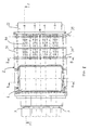
- Fig. 1 to 6 show an embodiment, wherein channels 23 are provided along the longitudinal extension of a feeding screw 3 so that perforations can be provided throughout the length of a feeding screw.
- Fig. 1 to 5 shows a device comprising four feeding screws 3 which are arranged in parallel to each other in a housing 2 of rectangular shape.
- a rectangular inlet opening 6 is provided on the upper side of the housing for connecting the housing 2 with a not shown filling hopper.
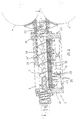
- FIG. 2 The longitudinal sectional view of Fig. 2 shows in more detail a mouth piece 22 between housing 2 and pressing rollers 4, 4'.
- channels 23 are provided in the housing 2, which channels 23 extend essentially along the length of the housing 2.
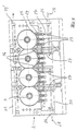
- Fig. 3 and 9 show three channels 23 which are arranged in parallel to each other in the area of a single feeding screw 3.
- Each channel 23 is connected with a plurality of small diameter bores 24 which extend between the channels 23 and the inner surface 25 of the housing 2.
- two rows of bores 24 are provided along a single channel 23 as can be seen in Fig. 4.
- ducts 26 are provided extending below of the channels 23 essentially perpendicular to these channels 23 in the lower part of the housing 2 as shown in Fig. 4. Vacuum and pressure air is supplied alternatingly to these ducts as indicated by arrows 28.
- Each duct 26 is connected with two channels 23 via vertical extending connecting bores 27.
- the ducts 26 have different length wherein the longest duct 26 extends up to the sixth channel 23 adjacent to the longitudinal center axis of the housing 2.
- a further duct 26 extends up to the fifth channel 23 from both sides of the housing 2 whereas the shortest duct 26 extends from the outside of the housing 2 up to the fourth channel 23 as shown in Fig. 4 and 5.
- each channel 23 is connected via two connecting bore 27 with two ducts 26. In this way vacuum and pressure air is supplied to all of the bores 24 of a channel 23 in an effective way.
- the housing 2 is composed of at least four parts, a lower part 30 provided with channels 23 and ducts 26, an upper part 31 provided with the inlet opening 6 as well front and end parts 32, 33 as shown in Fig. 7.
- the inner surface 25 of the lower part 30 (Fig. 3) is provided with perforations in the form of the bores 24.
- a filter cloth 11 extends over these perforations or bores 24, respectively.
- Said filter cloth 11 is held under tension by means of fastening elements in the form of bars 34 extending along grooves in the lower housing part 30 between the channels 23 and on both sides of the lower housing part 30.
- Said bars 34 are fastened by means of screws 35 on housing part 30 and the filter cloth 11 is clamped between bars 34 and housing part 30.
- a bar 36 of essentially triangular cross-section is provided between the feeding screws 3 to fill the triangular space between adjacent feeding screws as shown in Fig. 5 and 6. The filter cloth 11 is also clamped between this bar 36 and the housing part 30.
- the plate-like lower housing part 30 is provided with cooling passages 37 for circulating of a cooling medium within the housing part 30.
- one passage 37 extends across the channels 23 for supplying cooling medium and a further passage 37' is provided for return flow. Between these passages 37 and 37' connecting passages 38 are provided which extend vertically and along the longitudinal axis of the lower housing part 30 as can be seen in Fig. 6.
- ducts 26 can also be provided in the front and end parts 32 and 33 of the housing for supplying vacuum and compressed air to the channels 23.
- vacuum is applied over a longer period than compressed air. Further it is possible to apply vacuum as well as compressed air in the form of short pulses following each other.
- the described method of alternating application of vacuum and compressed air via a filter can be applied in various apparatuses for densifying and compacting pulverized material, for example, also in packaging assemblies, in which a high filling weight of the packing and a decrease of the pulver volume is important.
- the method and the device according to the invention can be applied in side feeders of extruders for light and aerated pulvers and so on.
Landscapes
- Engineering & Computer Science (AREA)
- Mechanical Engineering (AREA)
- Basic Packing Technique (AREA)
- Filling Or Emptying Of Bunkers, Hoppers, And Tanks (AREA)
- Air Transport Of Granular Materials (AREA)
- Screw Conveyors (AREA)
- Filtering Of Dispersed Particles In Gases (AREA)
- Disintegrating Or Milling (AREA)
- Press Drives And Press Lines (AREA)
- Auxiliary Devices For And Details Of Packaging Control (AREA)
- Feeding, Discharge, Calcimining, Fusing, And Gas-Generation Devices (AREA)
Priority Applications (1)
| Application Number | Priority Date | Filing Date | Title |
|---|---|---|---|
| EP02024550A EP1283169A3 (fr) | 1999-08-23 | 2000-08-23 | Procédé et appareil pour densifier du matériau pulvérulent |
Applications Claiming Priority (4)
| Application Number | Priority Date | Filing Date | Title |
|---|---|---|---|
| EP99116170 | 1999-08-23 | ||
| EP99116170 | 1999-08-23 | ||
| EP00954647A EP1206391B1 (fr) | 1999-08-23 | 2000-08-23 | Procede et dispositif permettant de densifier un materiau pulverise |
| EP02024550A EP1283169A3 (fr) | 1999-08-23 | 2000-08-23 | Procédé et appareil pour densifier du matériau pulvérulent |
Related Parent Applications (1)
| Application Number | Title | Priority Date | Filing Date |
|---|---|---|---|
| EP00954647A Division EP1206391B1 (fr) | 1999-08-23 | 2000-08-23 | Procede et dispositif permettant de densifier un materiau pulverise |
Publications (2)
| Publication Number | Publication Date |
|---|---|
| EP1283169A2 true EP1283169A2 (fr) | 2003-02-12 |
| EP1283169A3 EP1283169A3 (fr) | 2003-03-05 |
Family
ID=8238798
Family Applications (2)
| Application Number | Title | Priority Date | Filing Date |
|---|---|---|---|
| EP02024550A Withdrawn EP1283169A3 (fr) | 1999-08-23 | 2000-08-23 | Procédé et appareil pour densifier du matériau pulvérulent |
| EP00954647A Expired - Lifetime EP1206391B1 (fr) | 1999-08-23 | 2000-08-23 | Procede et dispositif permettant de densifier un materiau pulverise |
Family Applications After (1)
| Application Number | Title | Priority Date | Filing Date |
|---|---|---|---|
| EP00954647A Expired - Lifetime EP1206391B1 (fr) | 1999-08-23 | 2000-08-23 | Procede et dispositif permettant de densifier un materiau pulverise |
Country Status (12)
| Country | Link |
|---|---|
| US (1) | US6688345B1 (fr) |
| EP (2) | EP1283169A3 (fr) |
| JP (1) | JP2003507272A (fr) |
| KR (1) | KR20020029381A (fr) |
| CN (1) | CN1370123A (fr) |
| AT (1) | ATE252022T1 (fr) |
| AU (1) | AU6703000A (fr) |
| CA (1) | CA2382077A1 (fr) |
| DE (1) | DE60005972T2 (fr) |
| ES (1) | ES2207543T3 (fr) |
| TW (1) | TW495472B (fr) |
| WO (1) | WO2001014210A1 (fr) |
Cited By (1)
| Publication number | Priority date | Publication date | Assignee | Title |
|---|---|---|---|---|
| CN110834743A (zh) * | 2019-11-25 | 2020-02-25 | 无为和泰农业科技有限公司 | 一种大米加工包装机 |
Families Citing this family (6)
| Publication number | Priority date | Publication date | Assignee | Title |
|---|---|---|---|---|
| RU2502661C1 (ru) * | 2012-08-27 | 2013-12-27 | Закрытое Акционерное Общество "Твин Трейдинг Компани" | Способ вакуумно-пневматического транспортирования сыпучих материалов с высокой массовой концентрацией |
| RU2535821C1 (ru) * | 2013-10-31 | 2014-12-20 | Закрытое Акционерное Общество "Твин Трейдинг Компани" | Вакуумно-пневматическое устройство для транспортирования сыпучих материалов с высокой массовой концентрацией |
| CN105599927A (zh) * | 2016-01-20 | 2016-05-25 | 湖州浙宝冶金辅料有限公司 | 一种高钙粉全封闭封装系统 |
| DE102016207549A1 (de) * | 2016-05-02 | 2017-11-02 | Rovema Gmbh | Verfahren zur kontinuierlichen oder intermittierenden Herstellung von Schlauchbeutelverpackungen und Schlauchbeutelmaschinen |
| IT201600091025A1 (it) * | 2016-09-08 | 2018-03-08 | Ica Spa | Sistema e metodo per il confezionamento di polveri |
| KR102830938B1 (ko) | 2019-09-04 | 2025-07-08 | 삼성전자주식회사 | 의류건조기 |
Citations (2)
| Publication number | Priority date | Publication date | Assignee | Title |
|---|---|---|---|---|
| US3664385A (en) | 1971-02-12 | 1972-05-23 | Carter Eng Co | Method and apparatus for feeding and compacting finely divided particulate material |
| EP0125585A1 (fr) | 1983-05-11 | 1984-11-21 | Erkomat Oy | Equipement pour enlever l'air des matières pulvérulentes |
Family Cites Families (8)
| Publication number | Priority date | Publication date | Assignee | Title |
|---|---|---|---|---|
| GB668394A (en) * | 1948-05-01 | 1952-03-19 | Monsanto Chemicals | Improvements in or relating to method of and apparatus for densifying dry powdered solids |
| CH533537A (de) | 1970-12-21 | 1973-02-15 | Gericke & Co | Vorrichtung zum Abfüllen eines Behältnisses mit verdichtetem, pulvrigem Gut |
| IT938559B (it) * | 1971-12-13 | 1973-01-25 | Acma Spa | Perfezionamento all erogatore di dosi di prodotti polverulenti non scorrevoli in macchine confeziona trici multiple |
| FR2377937A1 (fr) * | 1977-01-20 | 1978-08-18 | Alfa Laval Ag | Procede et dispositif pour la desaeration des poudres, telles que poudres de lait |
| GB2034591B (en) * | 1978-11-07 | 1983-03-30 | Pimi Spa | Compacting device for particulate material |
| US5538053A (en) * | 1989-09-15 | 1996-07-23 | Better Agricultural Goals Corporation | Vacuum densifier with auger |
| US5894871A (en) * | 1997-08-26 | 1999-04-20 | Greer; David L. | Sand hopper for filling bags |
| US6102088A (en) * | 1997-09-03 | 2000-08-15 | Xerox Corporation | Vacuum valve shutoff for particulate filling system |
-
2000
- 2000-08-23 CA CA002382077A patent/CA2382077A1/fr not_active Abandoned
- 2000-08-23 AU AU67030/00A patent/AU6703000A/en not_active Abandoned
- 2000-08-23 CN CN00811924A patent/CN1370123A/zh active Pending
- 2000-08-23 EP EP02024550A patent/EP1283169A3/fr not_active Withdrawn
- 2000-08-23 AT AT00954647T patent/ATE252022T1/de not_active IP Right Cessation
- 2000-08-23 EP EP00954647A patent/EP1206391B1/fr not_active Expired - Lifetime
- 2000-08-23 DE DE60005972T patent/DE60005972T2/de not_active Expired - Fee Related
- 2000-08-23 WO PCT/EP2000/008237 patent/WO2001014210A1/fr not_active Ceased
- 2000-08-23 JP JP2001518318A patent/JP2003507272A/ja active Pending
- 2000-08-23 ES ES00954647T patent/ES2207543T3/es not_active Expired - Lifetime
- 2000-08-23 KR KR1020027002052A patent/KR20020029381A/ko not_active Withdrawn
- 2000-09-02 TW TW089117969A patent/TW495472B/zh not_active IP Right Cessation
-
2002
- 2002-08-06 US US10/069,903 patent/US6688345B1/en not_active Expired - Fee Related
Patent Citations (2)
| Publication number | Priority date | Publication date | Assignee | Title |
|---|---|---|---|---|
| US3664385A (en) | 1971-02-12 | 1972-05-23 | Carter Eng Co | Method and apparatus for feeding and compacting finely divided particulate material |
| EP0125585A1 (fr) | 1983-05-11 | 1984-11-21 | Erkomat Oy | Equipement pour enlever l'air des matières pulvérulentes |
Cited By (1)
| Publication number | Priority date | Publication date | Assignee | Title |
|---|---|---|---|---|
| CN110834743A (zh) * | 2019-11-25 | 2020-02-25 | 无为和泰农业科技有限公司 | 一种大米加工包装机 |
Also Published As
| Publication number | Publication date |
|---|---|
| CA2382077A1 (fr) | 2001-03-01 |
| DE60005972T2 (de) | 2004-09-09 |
| JP2003507272A (ja) | 2003-02-25 |
| ATE252022T1 (de) | 2003-11-15 |
| KR20020029381A (ko) | 2002-04-18 |
| TW495472B (en) | 2002-07-21 |
| DE60005972D1 (de) | 2003-11-20 |
| EP1206391B1 (fr) | 2003-10-15 |
| CN1370123A (zh) | 2002-09-18 |
| WO2001014210A1 (fr) | 2001-03-01 |
| ES2207543T3 (es) | 2004-06-01 |
| EP1206391A1 (fr) | 2002-05-22 |
| EP1283169A3 (fr) | 2003-03-05 |
| AU6703000A (en) | 2001-03-19 |
| US6688345B1 (en) | 2004-02-10 |
Similar Documents
| Publication | Publication Date | Title |
|---|---|---|
| EP1283169A2 (fr) | Procédé et appareil pour densifier du matériau pulvérulent | |
| EP0089114A2 (fr) | Collecteur de poussière | |
| KR100952181B1 (ko) | 복합담배필터의 고속충전방법 및 장치 | |
| WO2011117981A1 (fr) | Dispositif d'alimentation de fagots de cigarettes | |
| CA2180436C (fr) | Dispositif de filtration a tissus filtrants | |
| FI92476B (fi) | Virtauksen jakava V-seula | |
| US20250099892A1 (en) | Modular filter system with shake and pulse cleaning for dusty enclosures | |
| CZ273996A3 (en) | Apparatus for separating heavy particles of material from lighter particles | |
| WO1986007290A1 (fr) | Appareil de criblage avec dispositif integre de distribution et de separation | |
| CN217164846U (zh) | 一种低含矸率物料梯流分选机 | |
| GB2048723A (en) | Screen for a screening machine | |
| AU762635B2 (en) | Dust filter | |
| SU906627A1 (ru) | Барабанный грохот | |
| PL202408B1 (pl) | Urządzenie do obróbki materiałów w postaci arkuszy za pomocą strumieni wody pod ciśnieniem | |
| US5251763A (en) | Conveying apparatus and separation apparatus | |
| SE452216B (sv) | Sett och aggregat for laddning av en filtreringstank med adsorberande, partikelformigt filtermaterial | |
| CA1173084A (fr) | Dispositif d'apport-etalement de houille granulee | |
| CA2010897A1 (fr) | Crible | |
| JPH03500848A (ja) | タバコなどの微粒子材料の空気力搬送のための装置 | |
| PL155757B1 (en) | Dust collection filter for use in mines | |
| CZ257994A3 (en) | Tangential separation chamber | |
| ATE269166T1 (de) | Gerät zum reinigen einer suspension, insbesondere einer suspension aus einer fasermasse | |
| CN216463500U (zh) | 一种用于生产雷电接收带的板材打磨装置 | |
| CN102553367A (zh) | 过滤装置 | |
| PL98510B1 (pl) | Sposob oddzielania zanieczyszczen z materialow polidyspersyjnych oraz urzadzenie do oddzielania zanieczyszczen z materialow polidyspersyjnych |
Legal Events
| Date | Code | Title | Description |
|---|---|---|---|
| PUAI | Public reference made under article 153(3) epc to a published international application that has entered the european phase |
Free format text: ORIGINAL CODE: 0009012 |
|
| PUAL | Search report despatched |
Free format text: ORIGINAL CODE: 0009013 |
|
| AC | Divisional application: reference to earlier application |
Ref document number: 1206391 Country of ref document: EP Kind code of ref document: P |
|
| AK | Designated contracting states |
Designated state(s): AT BE CH CY DE DK ES FI FR GB GR IE IT LI LU MC NL PT SE |
|
| AK | Designated contracting states |
Designated state(s): AT BE CH CY DE DK ES FI FR GB GR IE IT LI LU MC NL PT SE Kind code of ref document: A3 Designated state(s): AT BE CH CY DE DK ES FI FR GB GR IE IT LI LU MC NL PT SE |
|
| RIC1 | Information provided on ipc code assigned before grant |
Ipc: 7B 65G 33/18 B Ipc: 7B 65B 37/10 B Ipc: 7B 65B 63/02 B Ipc: 7B 65B 1/12 A |
|
| 17P | Request for examination filed |
Effective date: 20021104 |
|
| 17Q | First examination report despatched |
Effective date: 20030909 |
|
| AKX | Designation fees paid |
Designated state(s): AT BE CH CY DE DK ES FI FR GB GR IE IT LI LU MC NL PT SE |
|
| GRAP | Despatch of communication of intention to grant a patent |
Free format text: ORIGINAL CODE: EPIDOSNIGR1 |
|
| STAA | Information on the status of an ep patent application or granted ep patent |
Free format text: STATUS: THE APPLICATION IS DEEMED TO BE WITHDRAWN |
|
| 18D | Application deemed to be withdrawn |
Effective date: 20040918 |