EP1283319B1 - Paroi de séparation - Google Patents
Paroi de séparation Download PDFInfo
- Publication number
- EP1283319B1 EP1283319B1 EP02017297.9A EP02017297A EP1283319B1 EP 1283319 B1 EP1283319 B1 EP 1283319B1 EP 02017297 A EP02017297 A EP 02017297A EP 1283319 B1 EP1283319 B1 EP 1283319B1
- Authority
- EP
- European Patent Office
- Prior art keywords
- hinge
- wall
- door
- door element
- wall element
- Prior art date
- Legal status (The legal status is an assumption and is not a legal conclusion. Google has not performed a legal analysis and makes no representation as to the accuracy of the status listed.)
- Expired - Lifetime
Links
Images

Classifications
-
- E—FIXED CONSTRUCTIONS
- E05—LOCKS; KEYS; WINDOW OR DOOR FITTINGS; SAFES
- E05D—HINGES OR SUSPENSION DEVICES FOR DOORS, WINDOWS OR WINGS
- E05D3/00—Hinges with pins
- E05D3/06—Hinges with pins with two or more pins
- E05D3/12—Hinges with pins with two or more pins with two parallel pins and one arm
- E05D3/122—Gear hinges
-
- A—HUMAN NECESSITIES
- A47—FURNITURE; DOMESTIC ARTICLES OR APPLIANCES; COFFEE MILLS; SPICE MILLS; SUCTION CLEANERS IN GENERAL
- A47K—SANITARY EQUIPMENT; ACCESSORIES THEREFOR, e.g. TOILET ACCESSORIES
- A47K3/00—Baths; Showers; Appurtenances therefor
- A47K3/28—Showers or bathing douches
- A47K3/30—Screens or collapsible cabinets for showers or baths
- A47K3/36—Articulated screens
-
- E—FIXED CONSTRUCTIONS
- E04—BUILDING
- E04B—GENERAL BUILDING CONSTRUCTIONS; WALLS, e.g. PARTITIONS; ROOFS; FLOORS; CEILINGS; INSULATION OR OTHER PROTECTION OF BUILDINGS
- E04B2/00—Walls, e.g. partitions, for buildings; Wall construction with regard to insulation; Connections specially adapted to walls
- E04B2/74—Removable non-load-bearing partitions; Partitions with a free upper edge
- E04B2/7407—Removable non-load-bearing partitions; Partitions with a free upper edge assembled using frames with infill panels or coverings only; made-up of panels and a support structure incorporating posts
- E04B2/7416—Removable non-load-bearing partitions; Partitions with a free upper edge assembled using frames with infill panels or coverings only; made-up of panels and a support structure incorporating posts with free upper edge, e.g. for use as office space dividers
- E04B2/7422—Removable non-load-bearing partitions; Partitions with a free upper edge assembled using frames with infill panels or coverings only; made-up of panels and a support structure incorporating posts with free upper edge, e.g. for use as office space dividers with separate framed panels without intermediary support posts
- E04B2/7424—Glazing details
-
- E—FIXED CONSTRUCTIONS
- E04—BUILDING
- E04B—GENERAL BUILDING CONSTRUCTIONS; WALLS, e.g. PARTITIONS; ROOFS; FLOORS; CEILINGS; INSULATION OR OTHER PROTECTION OF BUILDINGS
- E04B2/00—Walls, e.g. partitions, for buildings; Wall construction with regard to insulation; Connections specially adapted to walls
- E04B2/74—Removable non-load-bearing partitions; Partitions with a free upper edge
- E04B2/7407—Removable non-load-bearing partitions; Partitions with a free upper edge assembled using frames with infill panels or coverings only; made-up of panels and a support structure incorporating posts
- E04B2/7416—Removable non-load-bearing partitions; Partitions with a free upper edge assembled using frames with infill panels or coverings only; made-up of panels and a support structure incorporating posts with free upper edge, e.g. for use as office space dividers
- E04B2/7422—Removable non-load-bearing partitions; Partitions with a free upper edge assembled using frames with infill panels or coverings only; made-up of panels and a support structure incorporating posts with free upper edge, e.g. for use as office space dividers with separate framed panels without intermediary support posts
- E04B2/7427—Removable non-load-bearing partitions; Partitions with a free upper edge assembled using frames with infill panels or coverings only; made-up of panels and a support structure incorporating posts with free upper edge, e.g. for use as office space dividers with separate framed panels without intermediary support posts with adjustable angular connection of panels
- E04B2/7431—Removable non-load-bearing partitions; Partitions with a free upper edge assembled using frames with infill panels or coverings only; made-up of panels and a support structure incorporating posts with free upper edge, e.g. for use as office space dividers with separate framed panels without intermediary support posts with adjustable angular connection of panels using hinges having two parallel rotation axes
-
- E—FIXED CONSTRUCTIONS
- E05—LOCKS; KEYS; WINDOW OR DOOR FITTINGS; SAFES
- E05D—HINGES OR SUSPENSION DEVICES FOR DOORS, WINDOWS OR WINGS
- E05D5/00—Construction of single parts, e.g. the parts for attachment
- E05D5/02—Parts for attachment, e.g. flaps
- E05D5/0246—Parts for attachment, e.g. flaps for attachment to glass panels
-
- E—FIXED CONSTRUCTIONS
- E05—LOCKS; KEYS; WINDOW OR DOOR FITTINGS; SAFES
- E05D—HINGES OR SUSPENSION DEVICES FOR DOORS, WINDOWS OR WINGS
- E05D3/00—Hinges with pins
- E05D3/06—Hinges with pins with two or more pins
- E05D3/08—Hinges with pins with two or more pins for swing-doors, i.e. openable by pushing from either side
-
- E—FIXED CONSTRUCTIONS
- E05—LOCKS; KEYS; WINDOW OR DOOR FITTINGS; SAFES
- E05Y—INDEXING SCHEME ASSOCIATED WITH SUBCLASSES E05D AND E05F, RELATING TO CONSTRUCTION ELEMENTS, ELECTRIC CONTROL, POWER SUPPLY, POWER SIGNAL OR TRANSMISSION, USER INTERFACES, MOUNTING OR COUPLING, DETAILS, ACCESSORIES, AUXILIARY OPERATIONS NOT OTHERWISE PROVIDED FOR, APPLICATION THEREOF
- E05Y2800/00—Details, accessories and auxiliary operations not otherwise provided for
-
- E—FIXED CONSTRUCTIONS
- E05—LOCKS; KEYS; WINDOW OR DOOR FITTINGS; SAFES
- E05Y—INDEXING SCHEME ASSOCIATED WITH SUBCLASSES E05D AND E05F, RELATING TO CONSTRUCTION ELEMENTS, ELECTRIC CONTROL, POWER SUPPLY, POWER SIGNAL OR TRANSMISSION, USER INTERFACES, MOUNTING OR COUPLING, DETAILS, ACCESSORIES, AUXILIARY OPERATIONS NOT OTHERWISE PROVIDED FOR, APPLICATION THEREOF
- E05Y2800/00—Details, accessories and auxiliary operations not otherwise provided for
- E05Y2800/67—Materials; Strength alteration thereof
- E05Y2800/672—Glass
-
- E—FIXED CONSTRUCTIONS
- E05—LOCKS; KEYS; WINDOW OR DOOR FITTINGS; SAFES
- E05Y—INDEXING SCHEME ASSOCIATED WITH SUBCLASSES E05D AND E05F, RELATING TO CONSTRUCTION ELEMENTS, ELECTRIC CONTROL, POWER SUPPLY, POWER SIGNAL OR TRANSMISSION, USER INTERFACES, MOUNTING OR COUPLING, DETAILS, ACCESSORIES, AUXILIARY OPERATIONS NOT OTHERWISE PROVIDED FOR, APPLICATION THEREOF
- E05Y2900/00—Application of doors, windows, wings or fittings thereof
- E05Y2900/10—Application of doors, windows, wings or fittings thereof for buildings or parts thereof
- E05Y2900/114—Application of doors, windows, wings or fittings thereof for buildings or parts thereof for showers
-
- E—FIXED CONSTRUCTIONS
- E05—LOCKS; KEYS; WINDOW OR DOOR FITTINGS; SAFES
- E05Y—INDEXING SCHEME ASSOCIATED WITH SUBCLASSES E05D AND E05F, RELATING TO CONSTRUCTION ELEMENTS, ELECTRIC CONTROL, POWER SUPPLY, POWER SIGNAL OR TRANSMISSION, USER INTERFACES, MOUNTING OR COUPLING, DETAILS, ACCESSORIES, AUXILIARY OPERATIONS NOT OTHERWISE PROVIDED FOR, APPLICATION THEREOF
- E05Y2999/00—Subject-matter not otherwise provided for in this subclass
Definitions
- the invention relates to a partition, in particular shower partition, according to the features indicated in the preamble of claim 1.
- Such a partition is made of EP 0 206 859 A1 Known, with hinge elements whose legs surround the edge of the wall element or door element.
- the hinges are arranged at the vertically aligned longitudinal edges of the wall element and the door element in the vertical direction spaced.
- the hinge elements contain in recesses of the wall element or the door element engaging bearing body with the hinge pin, wherein a connecting body is provided, which is at least partially disposed in a recess of the bearing body and is pivotally coupled to the respective hinge pin.
- Hinges known whose hinge elements have hinge plates and cover plates.
- the hinge plate and the cover plate of the respective hinge element abut against opposite surfaces of the associated wall element or door element and are interconnected by means of connecting elements, wherein the wall element and the door element between the hinge element and the cover plate are clamped.
- Coupling body for a defined path of movement of the axially spaced hinge elements are not present.
- the hinges comprise a connecting body, the two hinge elements with a return device in the form of an established on the respective hinge plate and elastically deformable ring.
- a fitting for fixing a door leaf which has a bore spaced in the horizontal direction from a recess. In this hole engages a pin of a plate of the fitting, wherein the outer diameter of the pin corresponds to the inner diameter of said bore of the door leaf. Said plate bears against the one surface of the door leaf, and opposite another plate is provided, which is connected to a screw screwed into the pin. Furthermore, a rack and pinion drive is provided to adjust a hinge half, which contains a hinge eye, with respect to the door leaf and the two aforementioned plates. Coupling body for a defined trajectory of the door leaf with two such fittings are not present.
- a hinge with one-piece hinge elements are known, which are connected to a single connector body.
- the hinge elements contain at opposite end faces as coupling body formed interlocking external teeth.
- hinge elements which in turn are integrally formed.
- the hinge elements include a coupling body, which is arranged with respect to the pivot axes between two connecting bodies.
- connecting body and coupling body are not arranged in a recess of the hinge elements, but in the region of opposite end faces of the integrally formed hinge elements whose legs surround the outer surface of a frame of the wall element or of the door element.
- the wall element and the door element are designed as frameless plates, in particular made of glass.
- the hinges are arranged in the region of the outside of the shower partition wall on the wall element and the door element and the hinge axes about which the door element is pivotable relative to the wall element, are also in the region of the outside.
- the door element can be pivoted with respect to the wall element only by a pivoting range of the order of 900.
- the present invention seeks to develop the partition with little design effort to the effect that the door element in a simple and defined manner both when opening and when closing over large Angular ranges can be pivoted.
- the partition and in particular their hinges should have a low volume and require, with a simple production and handling should be possible. Furthermore, the hinge should be produced with a low production cost and require little installation effort to make the connection with the two elements.
- the partition according to the invention is characterized by a simple and functional design, according to which the hinge is partially disposed in recesses in the region of the mutually facing longitudinal edges of the wall element and the door element.
- the recesses are open to the respective longitudinal edges of the plates of the wall element or of the door element.
- the bearing bodies are at least partially disposed in the respective recess and the connection of said bearing body by means of two, preferably plate-shaped connecting bodies, the ends of which are pivotally coupled by means of hinge pins of the respective bearing body.
- the two connecting bodies are also partially arranged in said recesses of the plates, so that overall a compact space-saving design is guaranteed.
- the said hinge pins are suitably in the same vertical plane as the plates of the wall or door element.
- the bearing bodies are connected to hinge plates and with these integral components of the hinge element, wherein the hinge plates is arranged and fixed to the in the mounted state of the partition wall substantially vertical surface of the plate.
- the hinge plate and also the correspondingly formed cover plate contain, in principle, U-shaped recesses open in the direction of the longitudinal edge, wherein in the region of these recesses the in particular plate-shaped connecting body of the hinge elements is arranged.
- the cover plate and also by means of the hinge plate which is located in the plate of the wall or door element recess Covered so that the result is a compact design, an attractive design is nevertheless guaranteed stable and functional design.
- the wall element can be designed as, for example, on the edge of a shower tray wall element as well as as also hinged by means of other hinges wall element, in forming the shower partition as a folding wall.
- the wall element and the door element are frameless and in the manner according to the invention, the hinges are directly connected to the plates, wherein expediently spaced in the connecting region of the wall element and the door element two of the inventively designed and arranged hinges in the vertical direction , Expedient in the upper and lower corner of said wall and door elements are arranged.
- the door element both to the inside and in the outer space of the partition over a very large angular range of at least is approximately 180 ° pivotable.
- the hinges contain coupling bodies, which ensure positive guidance during pivoting of the door element with respect to the wall element or vice versa.
- the coupling bodies are preferably integrated in the bearing body, and rotatably connected to the associated hinge element and are engaged with each other.
- the coupling bodies on their mutually facing outer surfaces toothings or a flexible band. Since the coupling body are integrated into the bearing body or are directly connected to this, a functionally correct pivoting, for example, the door member with respect to the wall element, ensured practically without additional manufacturing effort or space requirement.
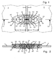
- Fig. 1 2 partially show the partition formed as a shower partition in a view or in a section in a horizontal sectional plane according to section line II, in the region of a hinge.
- the shower partition contains a wall element 2 and a door element 4, which are substantially vertically arranged plates, in particular made of silicate glass or acrylic glass, and in the region of their vertical longitudinal edges 6, 8 by means of two hinges, one of which is shown here, pivotally connected to each other are.
- the wall element 2 and the door element 4 are formed as so-called frameless elements, wherein the door element 4 is formed as a pivoting wing.
- the wall element 2 may for example be fixedly mounted on the edge of a shower or bath tub, or also be pivotally mounted with respect to another wall element or a wall profile or the like, wherein such a shower partition is also referred to as a folding wall.
- the two hinges are arranged spaced apart in the vertical direction, and expediently in the region of the upper or lower end of the wall and the Door element, and are formed consistently.
- the wall element 2 includes an open to the longitudinal edge 6, in principle U-shaped and expediently extending through the entire thickness of the wall member extending recess 12.
- the door element 4 for the respective hinge an open to its longitudinal edge 8, advantageously in principle U-shaped and expedient over the entire thickness of the door member 4 extending recess 14.
- the hinge elements 24, 26 are formed in a preferred manner coincident, so that the following explanations apply mutatis mutandis to the other hinge element of the hinge.
- the hinge member includes a voltage applied to the surface of the wall or door member 4 hinge plate 28 and a bearing body 30 which is disposed substantially within the recess 12 and 14 and engages in this.
- the bearing body 30 has a longitudinal edge 6 and 8 substantially parallel bore 32, 33, in each of which a hinge pin 34, 35 is arranged.
- the said holes and their hinge pins 34, 35 lie in the same vertical plane as the wall element 2 and door element 4, within the respective recess 12, 14.
- cover plates 36, 37 are arranged, which cover the said recesses and holes analogous to the hinge plates 28, 29, wherein further designed as screws 38, 39 connecting elements are provided.
- the hinge plates 28, 29 contain in the respective bore 32, 33 engaging projections 40, 41, in particular with threaded holes into which the screws 38, 39 are screwed.
- the lugs 40, 41 have a smaller outer diameter by a predetermined amount than the inner diameter of the bores 20, 22, so that the hinge elements 24, 26 with respect to the wall element 2 and door element 4 are aligned.
- the bearing body 30, 31 in particular contains a threaded bore for the screw 39.
- the bearing body 30, 31 has with respect to the recess 12, 14 smaller by a predetermined amount Outside dimensions such that the hinge element 24, 26 with respect to the wall element 2, 4 in the manner mentioned can be aligned.
- the wall element 2 or door element is like from Fig. 2 unmitelbar apparent, between the hinge plate 28, 29 and the associated cover plate 36, 37 clamped aligned, wherein by means of the screws 38, 39 a functionally reliable determination is ensured.
- connecting bodies 42, 43 are arranged in the region of the two recesses 12, 14, pass through the end portions of the hinge pins 34, 35. It should be noted here that in principle a single connecting body for connecting the wall element 2 with the door element 4 may be provided.
- the connecting bodies 42, 43 are preferably plate-shaped and are arranged substantially in the mutually opposite recesses 12 and 14 and in mutually opposite recesses 44, 46 of the hinge elements 24, 26 and the bearing body 30, 31.
- the cover plates 36, 37 similarly contain recesses 48, 50, through which the connecting bodies 42, 43 or their ends pass.
- coupling bodies 52, 54 are also provided. As shown, the coupling bodies 52, 54 include interlocking external gears 56, 58 and are penetrated by the hinge pins 34, 35.
- the coupling bodies 52, 54 are arranged rotationally fixed with respect to the hinge plate 28 and 29, respectively, according to Fig. 2 the coupling bodies 52, 54 bear against the hinge pins 34, 35 parallel contact surfaces on an opposite contact surface of the respective bearing body 30, 31.
- Fig. 3 shows a view of the hinge accordingly Fig. 1 , where well the attractive design of the overall quite small hinge plates 28, 29 can be seen.
- the above-explained recesses of the wall element 2 and the door element 4 and the holes for the connecting elements are covered by the hinge plates 28, 29 and by means of the underlying behind the plane cover plates and remain hidden from viewers.
- Fig. 3 shows the view from the outside of the shower partition in the closed state of the door member 4 in the direction of the separated by means of the shower partition from the outside space above a shower tray or the like.
- sealing elements in particular in the form of elastically yielding sealing strips or the like provided to prevent passage of spray water from the shower interior to the outside.
- Fig. 4 shows a top view of the shower partition in the region of the hinge, wherein by means of arrows 60, 62, the pivoting of the door element 4 with respect to the wall element 2 is indicated by 180 °.
- the shower partition has two vertically spaced hinges of the type according to the invention. By means of the coupling bodies 52, 54 of the two hinges arranged vertically one above the other, it is ensured that, when the door element 4 is pivoted in accordance with the arrows 60, 62, a synchronous movement takes place and the door element 4 remains vertically aligned and thus tilting out of the vertical position is prevented. Is in accordance with Fig.
- the door element 4 in the same vertical plane as the wall element 2, the shower interior 66 is separated from the shower outer space 64.
- the door element 4 can be pivoted both into the outer space 64 and into the inner space 66, up to a maximum of the indicated by dashed lines positions according to the means of the arrows 60 ,. 62 indicated pivoting angle of 180 °.
- the handling and use of the shower partition is significantly improved, especially since the door element 4 can be completely swung out of the passage area and a user thus unhindered get into the shower interior or can leave it again.
- the large pivoting angle range of the door element 4 is of considerable importance.
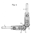
- Fig. 5 shows a plan view of the shower partition, wherein the door member 4 is pivoted with respect to the wall element 2 by an angle of 90 ° from the closed position.
- the plate-shaped connecting body 42 is shown with a continuous outer contour.
- the connecting body 42 applies to the other connecting bodies, is pivoted from the closed position or rest position, with respect to the hinge pin 34 of the wall element 2 by 45 °.
- the pivotal movements of all connecting bodies of the upper and lower hinge run synchronously and as a result, the door element 4, the vertical Retains alignment regardless of the respective pivot position.
- the outer contour of the parts or end portions of the connecting body 42 are rounded or circular in such a way that the interlocking external teeth 56, 58 of the coupling body 52, 54 are at least approximately covered. An entrapment of foreign bodies, a bath towel or the like is thus prevented in an advantageous manner.
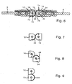
- Fig. 6 shows a particular embodiment of the partition wall according to the invention or its hinge, wherein in contrast to the above-described embodiment, the coupling body 52, 54 do not include external teeth for the positive coupling, but a flexible band 68 is provided.
- the flexible band 68 is made of such a flexible material that bends transversely to its longitudinal extent are feasible, but the length between its ends 70, 72 is maintained unchanged according to the invention.
- the flexible band 68 is particularly made of plastic, but it may be readily made of a flexible fabric, wires, a steel band or the like. Thickened according to the drawing executed ends 70, 71 are arranged in longitudinal grooves 72, 74, which preferably extend substantially parallel to the hinge pins 34, 35.
- the coupling bodies 52, 54 have coaxial to the hinge pins 34, 35 at least partially cylindrical outer surfaces 76, 78, to which the flexible band 68 corresponding to the respective pivot position of the door member 4 with respect to the wall element 2 abuts, the mutually facing cylindrical outer surfaces of the coupling body 52, 54th each extend over angles of substantially 180 °.
- the distance of the axes of the hinge pins 34, 35 at least approximately twice the radius of the coupling body 52, 54 and the thickness of the flexible band.
- Fig. 7 shows the coupling bodies 52, 54 and the flexible band 68 in the same position as Fig. 6 according to which the door element 4 is in the same vertical plane as the wall element 2.
- the door element 4 is pivoted by an angle of 90 ° and according to Fig. 9 at an angle of 180 °. It needs no special emphasis that starting from the basis of 6 and 7 explained position the door element and thus the coupling body 54 in the opposite direction 8 and 9 can also be pivoted by 90 or 180 °.
Landscapes
- Engineering & Computer Science (AREA)
- Architecture (AREA)
- Civil Engineering (AREA)
- Public Health (AREA)
- Physics & Mathematics (AREA)
- Health & Medical Sciences (AREA)
- Electromagnetism (AREA)
- Mechanical Engineering (AREA)
- Structural Engineering (AREA)
- Epidemiology (AREA)
- General Health & Medical Sciences (AREA)
- Hinges (AREA)
- Extensible Doors And Revolving Doors (AREA)
Claims (4)
- Paroi de séparation, en particulier une paroi de séparation de douche, comportant un élément de paroi (2) et un élément de porte (4) pivotant par rapport à celui-ci au moyen de deux charnières espacées dans la direction verticale, dans laquelle les charnières comportent deux éléments de charnière (24, 26) reliés d'une part à l'élément de paroi (2) et d'autre part à l'élément de porte (4), dans laquelle l'élément de paroi (2) et l'élément de porte (4) sont de préférence conçus comme des plaques sans cadre et comportent des arêtes longitudinales (6, 8) orientées essentiellement verticalement et tournées l'une vers l'autre dans la région des charnières, dans laquelle l'élément de paroi (2) et l'élément de porte (4) comportent des évidements (12, 14) respectivement ouverts vers leur arête longitudinale (6, 8), dans laquelle les éléments de charnière (24, 26) comportent des corps de support (28, 29) au moins partiellement engagés dans l'évidements correspondant (12, 14) de l'élément de porte (12) et de l'élément de paroi (14), avec un boulon de charnière (34, 35), et dans laquelle il est prévu au moins un corps de liaison (42, 43) agencé au moins partiellement dans un évidement (44, 46) du corps de support (30, 31) et accouplé de façon pivotante aux boulons de charnière (34, 35) respectifs de l'élément de charnière (28, 29) correspondant à l'élément de paroi (2) ou à l'élément de porte (4), dans laquelle les deux éléments de charnière (24, 26) comprennent une plaque de charnière (28, 29) appliquée contre la surface extérieure de l'élément de paroi (2) ou de l'élément de porte (4) et recouvrant l'évidement (12, 14) respectif de l'élément de porte (12) et de l'élément de paroi (14), et comportent une plaque de recouvrement (36, 37) agencée sur les côtés opposés de l'élément de paroi (2) ou de l'élément de porte (4), et dans laquelle les éléments de charnière (24, 26) comprenant les plaques de charnière (28, 29) et les corps de support (30, 31) comportent des évidements en forme de U (44, 46) ouverts vers l'arête longitudinale (6, 8), et les plaques de recouvrement (36, 37) comportent des évidements en forme de U (48, 50) ouverts vers l'arête longitudinale (6, 8), dans laquelle la plaque de charnière (28, 29) et la plaque de recouvrement (36, 37) sont reliées au moyen d'éléments de liaison (38, 39) et dans laquelle l'élément de paroi (2) et l'élément de porte (4) sont serrés entre ledit élément de charnière (24, 26) et la plaque de recouvrement (36, 37), et dans laquelle l'élément de paroi (2) et l'élément de porte (4) comportent des alésages (20, 22) dans lesquels s'engagent des appendices (40, 41) des plaques de charnière (28, 29), dont le diamètre extérieur est inférieur au diamètre intérieur des alésages (20, 22) selon une valeur prédéfinie, dans laquelle les éléments de liaison conçus comme des vis (38, 39) sont vissés dans les appendices (40, 41) et dans laquelle le corps de liaison (42, 43) est agencé essentiellement à l'intérieur de l'évidement (44, 46) des éléments de charnière (24, 26) et de l'évidement (48, 50) de la plaque de recouvrement (36, 37),
caractérisée en ce que les éléments de charnière (24, 26) comportent des corps d'accouplement (52, 54) en prise active l'un avec l'autre, de manière à définir une voie de déplacement des deux charnières montées de façon espacée verticalement l'une de l'autre, et en ce que les corps d'accouplement (52, 54) comportent des dentures (56, 58) engrenant l'une avec l'autre ou sont accouplés au moyen d'une bande souple (68), de manière à définir un déplacement synchronisé des deux charnières montées de façon espacée verticalement l'une de l'autre, l'élément de porte (4) demeurant orienté verticalement,
en ce que les corps d'accouplement (52, 54) sont agencés entre deux corps de liaison (42, 43) dans la direction du boulon de charnière (34, 35) respectivement correspondant, dans laquelle le boulon de charnière (34, 35) traverse les corps de liaison (42, 43) ainsi que les corps d'accouplement (52, 54), tout en étant fixé dans le corps de support (30, 31) par ses deux extrémités,
en ce que les corps d'accouplement (52, 54) s'appliquent avec une surface d'appui parallèle aux boulons de charnière (34, 35) contre une surface d'appui opposée du corps de support (30, 31) respectif, tout en étant agencés fixes en rotation par rapport à la plaque de charnière (28 ou 29),
en ce que les corps d'accouplement (52, 54) sont agencés essentiellement à l'intérieur de l'évidement (44, 46) des éléments de charnière (24, 26) et de l'évidement (48, 50) de la plaque de recouvrement (36, 37),
et en ce que les alésages (20, 22) sont agencés selon un espacement prédéfini (16, 18) par rapport aux arêtes longitudinales (6, 8), dans la direction horizontale par rapport aux évidements (12, 14) de l'élément de porte (2) et de l'élément de paroi (4) - Paroi de séparation selon la revendication 1, caractérisée en ce que le corps de support (30, 31) est relié fixement à la plaque de recouvrement (36, 37) au moyen d'éléments de liaison (38, 39), en particulier conçus comme des vis.
- Paroi de séparation selon la revendication 1 ou 2, caractérisée en ce que l'évidement (12, 14) dans l'élément de paroi (2) ou l'élément de porte (4) présente un contour ouvert vers l'arête longitudinale (6 ou 8) et de préférence essentiellement en forme de U, et/ou en ce que l'évidement (44, 46) dans l'élément de charnière (24, 26) est conçu ouvert vers l'élément de charnière (26, 24) respectivement opposé et présente un contour de préférence essentiellement en forme de U.
- Paroi de séparation selon l'une des revendications 1 à 3, caractérisée en ce que le boulon de charnière (34, 35) est agencé au moins approximativement essentiellement dans le même plan vertical que l'élément de paroi (2) ou l'élément de porte (4).
Applications Claiming Priority (2)
| Application Number | Priority Date | Filing Date | Title |
|---|---|---|---|
| DE20112966 | 2001-08-10 | ||
| DE20112966U | 2001-08-10 |
Publications (4)
| Publication Number | Publication Date |
|---|---|
| EP1283319A2 EP1283319A2 (fr) | 2003-02-12 |
| EP1283319A8 EP1283319A8 (fr) | 2003-05-28 |
| EP1283319A3 EP1283319A3 (fr) | 2010-03-03 |
| EP1283319B1 true EP1283319B1 (fr) | 2014-07-23 |
Family
ID=7960189
Family Applications (1)
| Application Number | Title | Priority Date | Filing Date |
|---|---|---|---|
| EP02017297.9A Expired - Lifetime EP1283319B1 (fr) | 2001-08-10 | 2002-08-01 | Paroi de séparation |
Country Status (4)
| Country | Link |
|---|---|
| EP (1) | EP1283319B1 (fr) |
| DE (1) | DE20211901U1 (fr) |
| DK (1) | DK1283319T3 (fr) |
| ES (1) | ES2496492T3 (fr) |
Cited By (2)
| Publication number | Priority date | Publication date | Assignee | Title |
|---|---|---|---|---|
| DE202018005400U1 (de) | 2017-12-04 | 2018-12-13 | Schulte Duschkabinenbau Gmbh & Co. Kg | Scharnier und Duschabtrennung |
| DE202018005401U1 (de) | 2017-12-04 | 2018-12-13 | Schulte Duschkabinenbau Gmbh & Co. Kg | Scharnier und Duschabtrennung |
Families Citing this family (2)
| Publication number | Priority date | Publication date | Assignee | Title |
|---|---|---|---|---|
| DE20304389U1 (de) | 2003-03-18 | 2003-06-05 | Altura Leiden Holding B.V., Vianen | Trennwand |
| CN108979391A (zh) * | 2018-06-12 | 2018-12-11 | 余兆生 | 一种淋浴房用的开门和关门止位的合页 |
Family Cites Families (7)
| Publication number | Priority date | Publication date | Assignee | Title |
|---|---|---|---|---|
| FR2582342B1 (fr) * | 1985-05-24 | 1987-07-17 | Guidotti Dante | Charniere pour la liaison de panneaux articules ou similaires |
| DE3938116A1 (de) * | 1989-11-16 | 1991-05-29 | Duewag Ag | Halterung einer drehtuer, insbesondere fuer den innenraum eines schienenfahrzeuges |
| FR2748515B1 (fr) * | 1996-05-09 | 1999-08-20 | Adler Sa | Charniere a systeme de rappel par anneau elastique |
| DE19649352B4 (de) * | 1996-11-28 | 2004-11-25 | Hüppe GmbH & Co. KG | Beschlag zum Befestigen eines Türflügels, insbesondere eines Türflügels einer Duschabtrennung aus Glas, Kunststoff oder dergleichen |
| WO1999002807A1 (fr) * | 1997-07-11 | 1999-01-21 | Sfs Ind Holding Ag | Assemblage articule servant par ex. de ferrure pour meuble ou pour porte |
| US5966777A (en) * | 1998-04-17 | 1999-10-19 | Versare Solutions, Inc. | Hinge |
| DE29910496U1 (de) | 1999-06-16 | 1999-08-12 | Altura Leiden Holding B.V., Vianen | Duschtrennwand |
-
2002
- 2002-08-01 DE DE20211901U patent/DE20211901U1/de not_active Expired - Lifetime
- 2002-08-01 DK DK02017297.9T patent/DK1283319T3/da active
- 2002-08-01 EP EP02017297.9A patent/EP1283319B1/fr not_active Expired - Lifetime
- 2002-08-01 ES ES02017297.9T patent/ES2496492T3/es not_active Expired - Lifetime
Cited By (2)
| Publication number | Priority date | Publication date | Assignee | Title |
|---|---|---|---|---|
| DE202018005400U1 (de) | 2017-12-04 | 2018-12-13 | Schulte Duschkabinenbau Gmbh & Co. Kg | Scharnier und Duschabtrennung |
| DE202018005401U1 (de) | 2017-12-04 | 2018-12-13 | Schulte Duschkabinenbau Gmbh & Co. Kg | Scharnier und Duschabtrennung |
Also Published As
| Publication number | Publication date |
|---|---|
| EP1283319A8 (fr) | 2003-05-28 |
| ES2496492T3 (es) | 2014-09-19 |
| DE20211901U1 (de) | 2002-10-02 |
| EP1283319A2 (fr) | 2003-02-12 |
| DK1283319T3 (da) | 2014-09-22 |
| EP1283319A3 (fr) | 2010-03-03 |
Similar Documents
| Publication | Publication Date | Title |
|---|---|---|
| DE60003494T3 (de) | Verstecktes Scharnier, insbesondere für Türen und/oder Flügel von Möbelelementen | |
| EP1946686B1 (fr) | Cloison de séparation, en particulier cloison de douche | |
| EP1460220A2 (fr) | Cloison | |
| EP0228527A2 (fr) | Ferrure pour portes et fenêtres | |
| EP1283319B1 (fr) | Paroi de séparation | |
| DE4322567C1 (de) | Trennwand für Dusche mit Schwenktüre und Scharnieren | |
| EP2098148B1 (fr) | Paroi de séparation dotée d'une bande articulée | |
| EP0652345A1 (fr) | Charnière réglable pour portes ou fenêtres | |
| EP3737816B1 (fr) | Charnière de meuble, panneau de meuble et corps de meuble | |
| EP2369111B1 (fr) | Palier d'angle caché | |
| EP1331335B1 (fr) | Séparation de douche | |
| DE29623000U1 (de) | Band | |
| EP1243212B1 (fr) | Cloison de douche | |
| DE9403956U1 (de) | Torblatt | |
| EP1563152B1 (fr) | Charniere | |
| EP2722472B1 (fr) | Ferrure pour battant et séparation de douche | |
| EP3871575A1 (fr) | Charnière | |
| EP1813751A1 (fr) | Charnière cachée | |
| EP0882864A2 (fr) | Charnière pour douche entièrement vitrée | |
| DE1270988B (de) | Scharnier, insbesondere fuer Glastueren | |
| EP1617025A2 (fr) | Charnière pour portes à fermeture bout à bout | |
| DE19918283B4 (de) | Tür- oder Fensterdrehband | |
| EP1898033B1 (fr) | Ferrure | |
| DE29804967U1 (de) | Tür- oder Fensterband | |
| EP1243215A2 (fr) | Cloison de douche |
Legal Events
| Date | Code | Title | Description |
|---|---|---|---|
| PUAI | Public reference made under article 153(3) epc to a published international application that has entered the european phase |
Free format text: ORIGINAL CODE: 0009012 |
|
| AK | Designated contracting states |
Designated state(s): AT BE BG CH CY CZ DE DK EE ES FI FR GB GR IE IT LI LU MC NL PT SE SK TR |
|
| AX | Request for extension of the european patent |
Extension state: AL LT LV MK RO SI |
|
| RIN1 | Information on inventor provided before grant (corrected) |
Inventor name: DER ERFINDER HAT AUF SEINE NENNUNG VERZICHTET. |
|
| PUAL | Search report despatched |
Free format text: ORIGINAL CODE: 0009013 |
|
| AK | Designated contracting states |
Kind code of ref document: A3 Designated state(s): AT BE BG CH CY CZ DE DK EE ES FI FR GB GR IE IT LI LU MC NL PT SE SK TR |
|
| AX | Request for extension of the european patent |
Extension state: AL LT LV MK RO SI |
|
| RIC1 | Information provided on ipc code assigned before grant |
Ipc: E05D 3/06 20060101AFI20021115BHEP Ipc: E05D 5/02 20060101ALI20100125BHEP |
|
| 17P | Request for examination filed |
Effective date: 20100730 |
|
| AKX | Designation fees paid |
Designated state(s): AT BE BG CH CY CZ DE DK EE ES FI FR GB GR IE IT LI LU MC NL PT SE SK TR |
|
| 17Q | First examination report despatched |
Effective date: 20110614 |
|
| GRAP | Despatch of communication of intention to grant a patent |
Free format text: ORIGINAL CODE: EPIDOSNIGR1 |
|
| RIC1 | Information provided on ipc code assigned before grant |
Ipc: E05D 3/06 20060101AFI20140325BHEP Ipc: E04B 2/74 20060101ALI20140325BHEP Ipc: E05D 3/12 20060101ALI20140325BHEP Ipc: A47K 3/36 20060101ALI20140325BHEP Ipc: E05D 5/02 20060101ALI20140325BHEP |
|
| INTG | Intention to grant announced |
Effective date: 20140416 |
|
| GRAS | Grant fee paid |
Free format text: ORIGINAL CODE: EPIDOSNIGR3 |
|
| GRAA | (expected) grant |
Free format text: ORIGINAL CODE: 0009210 |
|
| AK | Designated contracting states |
Kind code of ref document: B1 Designated state(s): AT BE BG CH CY CZ DE DK EE ES FI FR GB GR IE IT LI LU MC NL PT SE SK TR |
|
| REG | Reference to a national code |
Ref country code: GB Ref legal event code: FG4D Free format text: NOT ENGLISH |
|
| REG | Reference to a national code |
Ref country code: CH Ref legal event code: EP |
|
| REG | Reference to a national code |
Ref country code: IE Ref legal event code: FG4D Free format text: LANGUAGE OF EP DOCUMENT: GERMAN |
|
| REG | Reference to a national code |
Ref country code: AT Ref legal event code: REF Ref document number: 678992 Country of ref document: AT Kind code of ref document: T Effective date: 20140815 |
|
| REG | Reference to a national code |
Ref country code: DE Ref legal event code: R096 Ref document number: 50215953 Country of ref document: DE Effective date: 20140828 |
|
| REG | Reference to a national code |
Ref country code: ES Ref legal event code: FG2A Ref document number: 2496492 Country of ref document: ES Kind code of ref document: T3 Effective date: 20140919 |
|
| REG | Reference to a national code |
Ref country code: DK Ref legal event code: T3 Effective date: 20140919 |
|
| REG | Reference to a national code |
Ref country code: SE Ref legal event code: TRGR |
|
| REG | Reference to a national code |
Ref country code: NL Ref legal event code: T3 |
|
| PG25 | Lapsed in a contracting state [announced via postgrant information from national office to epo] |
Ref country code: BG Free format text: LAPSE BECAUSE OF FAILURE TO SUBMIT A TRANSLATION OF THE DESCRIPTION OR TO PAY THE FEE WITHIN THE PRESCRIBED TIME-LIMIT Effective date: 20141023 Ref country code: PT Free format text: LAPSE BECAUSE OF FAILURE TO SUBMIT A TRANSLATION OF THE DESCRIPTION OR TO PAY THE FEE WITHIN THE PRESCRIBED TIME-LIMIT Effective date: 20141124 Ref country code: FI Free format text: LAPSE BECAUSE OF FAILURE TO SUBMIT A TRANSLATION OF THE DESCRIPTION OR TO PAY THE FEE WITHIN THE PRESCRIBED TIME-LIMIT Effective date: 20140723 |
|
| PG25 | Lapsed in a contracting state [announced via postgrant information from national office to epo] |
Ref country code: CY Free format text: LAPSE BECAUSE OF FAILURE TO SUBMIT A TRANSLATION OF THE DESCRIPTION OR TO PAY THE FEE WITHIN THE PRESCRIBED TIME-LIMIT Effective date: 20140723 |
|
| REG | Reference to a national code |
Ref country code: DE Ref legal event code: R097 Ref document number: 50215953 Country of ref document: DE |
|
| PG25 | Lapsed in a contracting state [announced via postgrant information from national office to epo] |
Ref country code: EE Free format text: LAPSE BECAUSE OF FAILURE TO SUBMIT A TRANSLATION OF THE DESCRIPTION OR TO PAY THE FEE WITHIN THE PRESCRIBED TIME-LIMIT Effective date: 20140723 Ref country code: CZ Free format text: LAPSE BECAUSE OF FAILURE TO SUBMIT A TRANSLATION OF THE DESCRIPTION OR TO PAY THE FEE WITHIN THE PRESCRIBED TIME-LIMIT Effective date: 20140723 Ref country code: MC Free format text: LAPSE BECAUSE OF FAILURE TO SUBMIT A TRANSLATION OF THE DESCRIPTION OR TO PAY THE FEE WITHIN THE PRESCRIBED TIME-LIMIT Effective date: 20140723 Ref country code: SK Free format text: LAPSE BECAUSE OF FAILURE TO SUBMIT A TRANSLATION OF THE DESCRIPTION OR TO PAY THE FEE WITHIN THE PRESCRIBED TIME-LIMIT Effective date: 20140723 |
|
| REG | Reference to a national code |
Ref country code: IE Ref legal event code: MM4A |
|
| PLBE | No opposition filed within time limit |
Free format text: ORIGINAL CODE: 0009261 |
|
| STAA | Information on the status of an ep patent application or granted ep patent |
Free format text: STATUS: NO OPPOSITION FILED WITHIN TIME LIMIT |
|
| 26N | No opposition filed |
Effective date: 20150424 |
|
| REG | Reference to a national code |
Ref country code: FR Ref legal event code: PLFP Year of fee payment: 14 |
|
| PG25 | Lapsed in a contracting state [announced via postgrant information from national office to epo] |
Ref country code: IE Free format text: LAPSE BECAUSE OF NON-PAYMENT OF DUE FEES Effective date: 20140801 |
|
| PG25 | Lapsed in a contracting state [announced via postgrant information from national office to epo] |
Ref country code: GR Free format text: LAPSE BECAUSE OF FAILURE TO SUBMIT A TRANSLATION OF THE DESCRIPTION OR TO PAY THE FEE WITHIN THE PRESCRIBED TIME-LIMIT Effective date: 20140723 |
|
| PG25 | Lapsed in a contracting state [announced via postgrant information from national office to epo] |
Ref country code: LU Free format text: LAPSE BECAUSE OF NON-PAYMENT OF DUE FEES Effective date: 20140801 Ref country code: TR Free format text: LAPSE BECAUSE OF FAILURE TO SUBMIT A TRANSLATION OF THE DESCRIPTION OR TO PAY THE FEE WITHIN THE PRESCRIBED TIME-LIMIT Effective date: 20140723 |
|
| REG | Reference to a national code |
Ref country code: FR Ref legal event code: PLFP Year of fee payment: 15 |
|
| REG | Reference to a national code |
Ref country code: DE Ref legal event code: R082 Ref document number: 50215953 Country of ref document: DE Representative=s name: REBLE KLOSE SCHMITT PARTNERSCHAFTSGESELLSCHAFT, DE |
|
| REG | Reference to a national code |
Ref country code: FR Ref legal event code: PLFP Year of fee payment: 16 |
|
| PGFP | Annual fee paid to national office [announced via postgrant information from national office to epo] |
Ref country code: DK Payment date: 20170824 Year of fee payment: 16 |
|
| REG | Reference to a national code |
Ref country code: FR Ref legal event code: PLFP Year of fee payment: 17 |
|
| PGFP | Annual fee paid to national office [announced via postgrant information from national office to epo] |
Ref country code: FR Payment date: 20180824 Year of fee payment: 17 Ref country code: NL Payment date: 20180822 Year of fee payment: 17 Ref country code: ES Payment date: 20180921 Year of fee payment: 17 |
|
| PGFP | Annual fee paid to national office [announced via postgrant information from national office to epo] |
Ref country code: SE Payment date: 20180719 Year of fee payment: 9 |
|
| REG | Reference to a national code |
Ref country code: DK Ref legal event code: EBP Effective date: 20180831 |
|
| GBPC | Gb: european patent ceased through non-payment of renewal fee |
Effective date: 20180801 |
|
| PG25 | Lapsed in a contracting state [announced via postgrant information from national office to epo] |
Ref country code: DK Free format text: LAPSE BECAUSE OF NON-PAYMENT OF DUE FEES Effective date: 20180831 |
|
| PG25 | Lapsed in a contracting state [announced via postgrant information from national office to epo] |
Ref country code: GB Free format text: LAPSE BECAUSE OF NON-PAYMENT OF DUE FEES Effective date: 20180801 |
|
| REG | Reference to a national code |
Ref country code: NL Ref legal event code: MM Effective date: 20190901 |
|
| REG | Reference to a national code |
Ref country code: SE Ref legal event code: EUG |
|
| PG25 | Lapsed in a contracting state [announced via postgrant information from national office to epo] |
Ref country code: SE Free format text: LAPSE BECAUSE OF NON-PAYMENT OF DUE FEES Effective date: 20190802 |
|
| PG25 | Lapsed in a contracting state [announced via postgrant information from national office to epo] |
Ref country code: NL Free format text: LAPSE BECAUSE OF NON-PAYMENT OF DUE FEES Effective date: 20190901 Ref country code: FR Free format text: LAPSE BECAUSE OF NON-PAYMENT OF DUE FEES Effective date: 20190831 |
|
| PG25 | Lapsed in a contracting state [announced via postgrant information from national office to epo] |
Ref country code: IT Free format text: LAPSE BECAUSE OF NON-PAYMENT OF DUE FEES Effective date: 20190801 |
|
| REG | Reference to a national code |
Ref country code: ES Ref legal event code: FD2A Effective date: 20210105 |
|
| PG25 | Lapsed in a contracting state [announced via postgrant information from national office to epo] |
Ref country code: ES Free format text: LAPSE BECAUSE OF NON-PAYMENT OF DUE FEES Effective date: 20190802 |
|
| PGFP | Annual fee paid to national office [announced via postgrant information from national office to epo] |
Ref country code: AT Payment date: 20210818 Year of fee payment: 20 |
|
| PGFP | Annual fee paid to national office [announced via postgrant information from national office to epo] |
Ref country code: CH Payment date: 20210824 Year of fee payment: 20 Ref country code: DE Payment date: 20210819 Year of fee payment: 20 Ref country code: BE Payment date: 20210823 Year of fee payment: 20 |
|
| REG | Reference to a national code |
Ref country code: DE Ref legal event code: R081 Ref document number: 50215953 Country of ref document: DE Owner name: ALTURA LEIDEN HOLDING B.V., NL Free format text: FORMER OWNER: ALTURA LEIDEN HOLDING B.V., VIANEN, NL |
|
| REG | Reference to a national code |
Ref country code: DE Ref legal event code: R071 Ref document number: 50215953 Country of ref document: DE |
|
| REG | Reference to a national code |
Ref country code: CH Ref legal event code: PL |
|
| REG | Reference to a national code |
Ref country code: AT Ref legal event code: MK07 Ref document number: 678992 Country of ref document: AT Kind code of ref document: T Effective date: 20220801 |