EP1283326A1 - Refroidissement d'une aube de turbine - Google Patents
Refroidissement d'une aube de turbine Download PDFInfo
- Publication number
- EP1283326A1 EP1283326A1 EP01119263A EP01119263A EP1283326A1 EP 1283326 A1 EP1283326 A1 EP 1283326A1 EP 01119263 A EP01119263 A EP 01119263A EP 01119263 A EP01119263 A EP 01119263A EP 1283326 A1 EP1283326 A1 EP 1283326A1
- Authority
- EP
- European Patent Office
- Prior art keywords
- airfoil
- cooling medium
- cooling
- inflow
- turbine blade
- Prior art date
- Legal status (The legal status is an assumption and is not a legal conclusion. Google has not performed a legal analysis and makes no representation as to the accuracy of the status listed.)
- Granted
Links
- 238000001816 cooling Methods 0.000 title claims abstract description 70
- 239000002826 coolant Substances 0.000 claims abstract description 113
- 230000007423 decrease Effects 0.000 claims description 8
- 238000002485 combustion reaction Methods 0.000 description 5
- 230000000694 effects Effects 0.000 description 5
- 239000000446 fuel Substances 0.000 description 4
- 238000010276 construction Methods 0.000 description 3
- 238000013461 design Methods 0.000 description 3
- 239000002184 metal Substances 0.000 description 3
- 238000012546 transfer Methods 0.000 description 3
- 238000011161 development Methods 0.000 description 2
- 230000002349 favourable effect Effects 0.000 description 1
- 239000012530 fluid Substances 0.000 description 1
- 238000004519 manufacturing process Methods 0.000 description 1
- 238000012805 post-processing Methods 0.000 description 1
- 230000003014 reinforcing effect Effects 0.000 description 1
- 230000008646 thermal stress Effects 0.000 description 1
- 238000012549 training Methods 0.000 description 1
- 230000007704 transition Effects 0.000 description 1
Images


Classifications
-
- F—MECHANICAL ENGINEERING; LIGHTING; HEATING; WEAPONS; BLASTING
- F01—MACHINES OR ENGINES IN GENERAL; ENGINE PLANTS IN GENERAL; STEAM ENGINES
- F01D—NON-POSITIVE DISPLACEMENT MACHINES OR ENGINES, e.g. STEAM TURBINES
- F01D5/00—Blades; Blade-carrying members; Heating, heat-insulating, cooling or antivibration means on the blades or the members
- F01D5/12—Blades
- F01D5/14—Form or construction
- F01D5/18—Hollow blades, i.e. blades with cooling or heating channels or cavities; Heating, heat-insulating or cooling means on blades
- F01D5/187—Convection cooling
- F01D5/188—Convection cooling with an insert in the blade cavity to guide the cooling fluid, e.g. forming a separation wall
- F01D5/189—Convection cooling with an insert in the blade cavity to guide the cooling fluid, e.g. forming a separation wall the insert having a tubular cross-section, e.g. airfoil shape
-
- F—MECHANICAL ENGINEERING; LIGHTING; HEATING; WEAPONS; BLASTING
- F05—INDEXING SCHEMES RELATING TO ENGINES OR PUMPS IN VARIOUS SUBCLASSES OF CLASSES F01-F04
- F05D—INDEXING SCHEME FOR ASPECTS RELATING TO NON-POSITIVE-DISPLACEMENT MACHINES OR ENGINES, GAS-TURBINES OR JET-PROPULSION PLANTS
- F05D2260/00—Function
- F05D2260/20—Heat transfer, e.g. cooling
- F05D2260/201—Heat transfer, e.g. cooling by impingement of a fluid
-
- F—MECHANICAL ENGINEERING; LIGHTING; HEATING; WEAPONS; BLASTING
- F05—INDEXING SCHEMES RELATING TO ENGINES OR PUMPS IN VARIOUS SUBCLASSES OF CLASSES F01-F04
- F05D—INDEXING SCHEME FOR ASPECTS RELATING TO NON-POSITIVE-DISPLACEMENT MACHINES OR ENGINES, GAS-TURBINES OR JET-PROPULSION PLANTS
- F05D2260/00—Function
- F05D2260/20—Heat transfer, e.g. cooling
- F05D2260/205—Cooling fluid recirculation, i.e. after cooling one or more components is the cooling fluid recovered and used elsewhere for other purposes
Definitions
- the invention relates to a turbine blade with a extending along a blade axis, mainly in its longitudinal direction through which a cooling medium can flow Airfoil.
- Gas turbines are used to drive generators in many areas or used by work machines.
- the Energy content of a fuel to generate a rotational movement a turbine shaft used.
- the fuel will To do this, burned in a combustion chamber, using an air compressor compressed air is supplied. That in the combustion chamber generated by the combustion of the fuel, under high Pressure and high temperature working medium is via a turbine unit downstream of the combustion chamber managed where it relaxes while working.
- the turbine shaft To generate the rotational movement of the turbine shaft are a number of them usually in groups of blades or rows of blades grouped together arranged via a pulse transfer from the flow medium drive the turbine shaft.
- For guiding the flow medium are also common in the turbine unit between adjacent rows of blades with the turbine housing connected rows of vanes arranged.
- the turbine blades, in particular, the guide vanes usually have for appropriate guidance of the working medium along of an airfoil extending blade on the end for fastening the turbine blade to the respective Carrier body extending transversely to the blade axis Platform can be molded.
- the respective turbine blade usually has one integrated into the airfoil or the airfoil Cooling medium channel from which a cooling medium in particular targeted the thermally stressed zones of the turbine blade is feedable.
- Cooling air is usually used as the cooling medium. This is usually the case for the respective turbine blade in the manner of open cooling via an integrated one Coolant channel supplied. After exiting the turbine blade the cooling air is combined with that in the turbine unit led working medium mixed.
- the design performance a gas turbine cooled in this way is however limited, especially since in terms of limited mechanical Resilience of individual components of the gas turbine further increase in performance usually only by one increased fuel supply is achievable. This in turn requires a comparatively increased need for cooling medium to cool the turbine blades, which in turn losses in the available compressor mass flow means. These losses can only be accepted to a limited extent. It can also be required in gas turbines also with regard to Security may need to be mixed coolant flowing out of the turbine blade and the turbine unit to prevent working medium flowing through.
- the invention is therefore based on the object of a turbine blade of the type mentioned above for which with comparatively simple means a reliable and effective closed cooling, especially using of cooling air as a cooling medium.
- the invention is based on the consideration that a effective cooling for a turbine blade in particular with a flat application of the wall to be cooled of the airfoil can be achieved with cooling medium. It was recognized that such a flat application of a targeted Supply of the cooling medium to the wall and one Guidance of the cooling medium along this needs. This is achievable by a separate inflow and outflow channel is provided for cooling medium. Starting from this The cooling medium channel is divided into two the wall of the airfoil to be cooled in such a way that the cooling medium in the course of its transfer from the inflow led in the outflow channel in a transverse direction becomes.
- the cooling medium is guided mainly in the longitudinal direction of the airfoil enables compliance in particular short and thus loss-reduced flow paths for the Coolant flow.
- This main flow direction is changed only in a transverse direction in the area where a such change serves the targeted and effective cooling. Inevitable flow losses are at a low level held. Also an action on the airfoil with a comparatively large amount of cooling medium not hindered by restrictions in the flow path.
- a large cooling capacity in one comparatively small section of the flow path of the Cooling medium namely in the course of it in the transverse direction path section arranged to the airfoil, at the crossing from the inflow into the outflow channel.
- the inflow channel can be selected, particularly thermal assigned to highly stressed areas of the turbine blade Provide outlet openings for coolant to pass into have the outflow channel. It is particularly advantageous but when the inflow channel is roughly even over its Length distributes the inner wall of the airfoil to be cooled has facing outlet openings for the cooling medium. In this way, a flat is particularly simple Cooling of the airfoil achievable.
- the cooling can by means of a so-called impingement cooling, one the wall of the inflow channel having outlet openings as Baffle cooling wall serves with the cooling medium impinging on it comes into intensive contact and then through the outlet openings derived for crossing into the outflow channel can be.
- the free cross-section takes advantage of as specifically as possible of the inflow channel in the airfoil in its longitudinal direction preferably from. This takes account of the fact that an increasing part of the Cooling medium has already left the inflow channel and into the Outflow channel is exceeded.
- the turbine blade is particularly advantageous if the free cross section of the inflow channel in the airfoil in its The linear direction decreases linearly.
- the inflow channel for example very simply from flat sheet metal plates be educated.
- a very simple construction of the inflow and / or outflow channel for example from flat plates arises when the inflow channel and / or the outflow channel parallel to the longitudinal direction of the airfoil and perpendicular to the one to be cooled Inner wall of the airfoil according to an advantageous Training has a triangular cross section.
- the airfoil Turbine blade Since usually not all walls of the airfoil Turbine blade exposed to the same thermal loads , it may be sufficient to use only one inflow channel Cooling a thermally particularly stressed wall to be provided in the turbine blade. But especially if both the pressure and the suction side of the turbine blade must be cooled, it is advantageous to have a second inflow channel for cooling medium for cooling another inner wall to provide the airfoil, based on the Blade axis arranged symmetrically to the first inflow channel is. Because the inner walls to be cooled are opposite are arranged, the first and the second inflow channel open preferably in a common outflow channel for Cooling medium.
- the outflow channel can, for example, be inexpensive in run a central area of the airfoil.
- the cooling medium is guided along the inner wall to be cooled of the airfoil in its transverse direction even more targeted and reinforcing the cooling effect when according to another advantageous development, the or with several inner walls to be cooled - each to be cooled Inner wall of the airfoil with the cooling medium conductive ribs arranged transversely to the blade axis is. These fins also have an additional cooling fin effect result and thus further improve the cooling.
- the inflow channel is preferably at its one entry surface for the end facing away from the cooling medium and / or the outflow channel on its an outlet surface facing away from the cooling medium Locked at the beginning, making it easy to set up and a trouble-free supply and discharge of the cooling medium to the and made possible by the turbine blade.
- a turbine blade in which the Airfoil on its coolant outflow side a cross to the blade axis extending platform is formed if the platform is connected to the inflow channel Has cooling medium acted upon cooling chamber.
- the cooling medium of the one to be cooled becomes wise Inner wall of the airfoil feeds the design of the Turbine blade considerably simplifying at the same time as a feed channel of cooling medium used to the cooling chamber of the platform.
- a turbine blade is just as advantageous, on the airfoil on its cooling medium inflow side a platform is formed which extends transversely to the blade axis is the one connected to the outflow channel with Has cooling medium acted upon cooling chamber. It can the cooling medium used to cool the platform immediately can be discharged from the airfoil without expensive Return flow channels would have to be provided or that the There could be a risk of mixing with the cooling medium provided for cooling the inner wall of the airfoil is. The effective cooling of the airfoil is thus not endangered.
- the turbine blade is advantageously the or each cooling chamber poured into the respective platform and to the outside completed with a cover plate.
- the cooling chamber are produced directly when the turbine blade is cast, so that post-processing of the cast body is not necessary is.
- For the reliable closure of the respective cooling chamber to the outside is only the attachment of the respective Cover plate required.
- a particularly reliable cooling of the respective structural parts with cooling medium can be reached by means of impingement cooling.
- the or each cooling chamber is advantageous in one Floor area with a spaced from the chamber floor Provide baffle plate.
- the baffle plate is in the essentially formed as a perforated sheet, with the Impingement cooling plate impinging cooling medium with this in particular intensive contact occurs and then over the perforation can be derived.
- For reliable coolant drainage is in a further advantageous embodiment one limited by the chamber floor and the baffle cooling plate Outflow chamber of the cooling chamber connected to the outflow channel.
- Corresponding is for a reliable supply of cooling medium to the cooling chamber according to another advantageous development one through the cover plate and the baffle cooling plate limited flow chamber of the cooling chamber connected to the flow channel.
- the turbine blade is preferably used as a guide blade for a gas turbine, especially for a stationary gas turbine, educated.
- the advantages achieved with the invention are in particular in that by providing an inflow and an outflow channel the coolant in the turbine blade when it passes from the inflow into the outflow channel in a transverse direction is guided along the inside of the airfoil, whereby a flat application of the airfoil enables is and there is a particularly effective cooling.
- the Turbine blade is comparatively easy producible, it being particularly important that Inflow and outflow channel as simple inserts in the airfoil are mountable, can be designed.
- In addition is incorporating concepts in a comparatively simple way closed cooling with air as the cooling medium allows.
- the turbine blade 1 according to FIG. 1 has an airfoil 2, which extends along a blade axis 4.
- the Blade 2 is suitable for influencing a working fluid flowing in an associated turbine unit arched and / or curved.
- the turbine blade 1 is as a guide blade for one here Gas turbine not shown and in the manner of a closed Cooling as coolable with cooling air as cooling medium Turbine blade designed.
- an inflow channel 6 in the cooling medium K of the Coolant inflow side AS can come forth, and an outflow channel 8 out for cooling medium K. Via the outflow channel 8, the cooling medium can the airfoil 2 on the cooling medium outflow side Leave BS again.
- the inflow channel 6 is on the one hand by a flat, closed wall 10 which is diagonal runs in the airfoil 2, and on the other hand through a flat, outlet openings 12 for cooling medium K Wall 14 limited; the closed wall 10 and the outlet openings 12 wall 14 can be made of sheet metal be formed.
- wall 14 is parallel to one to be cooled Inner wall 16 of the airfoil 2 arranged, see above that between this inner wall 16 and the aforementioned wall 14th of the inflow channel 6, an overflow channel 18 is formed.
- the outflow channel 8 is limited on the one hand from the flat, closed wall 10 which diagonally in the airfoil 2 and the inflow channel 6 of the Outflow channel 8 separates, and on the other hand from an inner wall 22 of the airfoil 2, that of the inner wall to be cooled 16 is opposite.
- the arrangement is chosen such that the free cross section 40 of the inflow channel 6 in the airfoil 2 in its longitudinal direction L decreases linearly. At the same time increases with the measure this decrease, the free cross section 52 of the outflow channel 8 in the airfoil 2 in its longitudinal direction L. Moreover both the inflow channel 6 and the outflow channel 8 are parallel to the longitudinal direction L of the airfoil 2 and perpendicular a triangular cross-section to the inner wall 16 to be cooled on.
- the overflow of the cooling medium K from the inflow channel 6 in the outflow channel 8 illustrates Figure 2, the a cross section along line II - II through the turbine blade 1 according to FIG. 1.
- the inflow channel 6 has a closed wall 10 two more connecting the latter walls 10, 14 Walls 24, 26 so that the inflow channel 6 with the exception of one Entry surface and the outlet openings 12 closed is.
- the other walls 24, 26 can each of a sheet metal plate are formed.
- cooling medium K leaves this channel on the Outlet openings 12 and then hits the inner wall 16 of the airfoil 2.
- This results in an impact cooling effect which is further reinforced by the fact that the cooling medium K - additionally guided by ribs 20 - on the inner wall 16 of the airfoil 2 in its transverse direction Q is guided along and through overflow channels 18, 28, 30 reaches the outflow channel 8; the cooling medium flows K around at least part of the inflow channel 6 and arrives then in the discharge channel 8, through which it in turn Longitudinal direction of the airfoil 2 flows off. Because of the the inner wall 16 of the airfoil 2 arranged ribs 20 results in a cooling fin effect which increases the cooling effect.
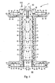
- FIG. 1 Another turbine blade 1 with an airfoil 2 3 shows a partially cut, perspective view.
- the airfoil 2 has a first and a second here Inflow channel 6, 32 for cooling medium K, the inflow channels 6, 32 based on the blade axis 4 symmetrical to each other are arranged and the airfoil 2 in its Pull lengthwise L over a length of 1.
- Cooling medium K occurs on the coolant inflow side AS of the airfoil 2 into the inflow channels 6, 32, flows through the airfoil 2 in its longitudinal direction L in both inflow channels 6, 32 and leaves it via outlet openings 12, which are shown in FIG for the sake of clarity, only in the first inflow channel 6 are shown.
- the cooling medium K then flows in one perpendicular to the longitudinal direction L of the airfoil 2 Transverse direction Q each on an inner wall to be cooled 16, 36 of the airfoil 2 along.
- These inner walls 16, 36 are the outlet openings 12 of the inflow channels 6, 32 arranged opposite and with - in Figure 3 the For the sake of clarity, only on the first inner wall to be cooled 16 shown - ribs 20 for guiding the cooling medium K provided.
- the flow along the inner walls to be cooled 16, 36 takes place during a transfer of the cooling medium K from the inflow channels 6, 32 into a common outflow channel 8 for cooling medium K, the middle between the inflow channels 6, 32 is arranged. Via the discharge channel 8 becomes the cooling medium K in the longitudinal direction L of the airfoil 2 fed to the cooling medium outflow side BS.
- the inflow channels 6, 32 each have an entry surface 34, 38 forming free cross-section of the same size.
- This free cross section of the inflow channels 6, 32 takes in the airfoil 2 linearly in its longitudinal direction L, so that at half length 1/2 the free cross section 40, 42 each also is halved when the inflow channels 6, 32 at their Entry surface 34, 38 for end 44 facing away from cooling medium K, 46 do not have a free cross section. That means at the same time that the inflow channels at this end 44, 46 are closed.
- the outflow channel 8 is at one of one free cross section formed outlet surface 48 for cooling medium K sealed at the beginning 50 and has no there free cross section.
- the free cross section of the outflow channel 8 in the airfoil 2 takes in its longitudinal direction L corresponding to the decrease in the free cross section of the Inflow channels 6, 32 too. Therefore, the free cross section 52 of the outflow channel 8 at half the length 1/2 of the airfoil 2 an area corresponding to the sum of the free cross sections 40, 42 of the inflow channels 6, 32 corresponds at this point. In order to free flow of the cooling medium K is guaranteed.
- the airfoil 2 In addition to a recess 54 running in the longitudinal direction L, in which arranged the inflow channels 6, 32 and the outflow channel 8 are, the airfoil 2 further in the longitudinal direction L extending recesses 56, 58, 60.
- the latter Recesses 56, 58, 60, shown as cavities in Figure 3 are also available with appropriate inflow and outflow channels be provided for cooling medium and for cooling the turbine blade 1 can be used.
- FIG. 1 Another turbine blade 1, in particular a guide blade can be for a gas turbine, with a two respect a blade axis 4 symmetrically arranged inflow channels 6, 32 for airfoil 2 having cooling medium K.
- Figure 4 in a longitudinal section.
- To the airfoil 2 is on a cooling medium inflow side AS a cross to the Shaped first platform 62 extending blade axis 4, which forms a head plate.
- On a coolant outflow side BS is a transverse to the blade axis 4, a second platform 64 forming a base plate is formed.
- cooling medium K occurs in the first on the coolant inflow side AS Platform 62 and in a shielded by a cover plate 66 central, connected to the inflow channels 6, 32 Area of the airfoil 2.
- a cooling chamber 68 of the first Platform 62 is connected to the outflow channel 8, so that already used for cooling the first platform 62 Cooling medium K through the outflow channel 8 directly can be led out of the airfoil 2.
- the cooling medium K supplied to the inflow channels 6, 32 leaves these inflow channels 6, 32 either through outlet openings 12, 70 in inner walls 16, 36 of the airfoil to be cooled 2 facing walls 14, 72 or by on the respective Entry surface for cooling medium K facing away from the Inflow channels 6, 32 provided transitions 74, 76 to one Cooling chamber 78 of the second platform 64.
- the cooling medium K, the through the outlet openings 12, 70 is in a transverse direction Q on the ribs 20, 80 to be cooled Inner walls 16, 36 of the airfoil 2 along out, then enters and leaves the outflow channel 8 via this the airfoil 2 on its cooling medium outflow side BS.
- the cooling chambers 68, 78 of the platforms 62, 64 are in these cast in and outwards through a cover plate 82, 84 completed.
- the cooling chambers 68, 78 each in its bottom area with a spacing from the chamber bottom 86, 88 arranged baffle cooling plate 90, 92 provided.
- An outflow space is in the cooling chamber 68 of the first platform 62 94 available through the chamber floor 86 and Baffle cooling plate 90 is limited and connected to the outflow channel 8 is.
- the cooling chamber 78 faces the second Platform 64 has an inflow space 96 through the cover plate 84 and the baffle plate 92 is limited and to the Inflow channels 6, 32 is connected. That way the inflow space 96 is fed by the inflow channels 6, 32, which are separated from the outflow channel 8 by walls 10, 98 are.
Landscapes
- Engineering & Computer Science (AREA)
- Mechanical Engineering (AREA)
- General Engineering & Computer Science (AREA)
- Turbine Rotor Nozzle Sealing (AREA)
Priority Applications (6)
| Application Number | Priority Date | Filing Date | Title |
|---|---|---|---|
| EP01119263A EP1283326B1 (fr) | 2001-08-09 | 2001-08-09 | Refroidissement d'une aube de turbine |
| ES01119263T ES2254296T3 (es) | 2001-08-09 | 2001-08-09 | Enfriamiento de un alabe de turbina. |
| DE50108466T DE50108466D1 (de) | 2001-08-09 | 2001-08-09 | Kühlung einer Turbinenschaufel |
| JP2002226904A JP4249959B2 (ja) | 2001-08-09 | 2002-08-05 | タービン翼 |
| CNB02128539XA CN1318733C (zh) | 2001-08-09 | 2002-08-09 | 燃气轮机叶片/导向叶片 |
| US10/214,760 US6905301B2 (en) | 2001-08-09 | 2002-08-09 | Turbine blade/vane |
Applications Claiming Priority (1)
| Application Number | Priority Date | Filing Date | Title |
|---|---|---|---|
| EP01119263A EP1283326B1 (fr) | 2001-08-09 | 2001-08-09 | Refroidissement d'une aube de turbine |
Publications (2)
| Publication Number | Publication Date |
|---|---|
| EP1283326A1 true EP1283326A1 (fr) | 2003-02-12 |
| EP1283326B1 EP1283326B1 (fr) | 2005-12-21 |
Family
ID=8178287
Family Applications (1)
| Application Number | Title | Priority Date | Filing Date |
|---|---|---|---|
| EP01119263A Expired - Lifetime EP1283326B1 (fr) | 2001-08-09 | 2001-08-09 | Refroidissement d'une aube de turbine |
Country Status (6)
| Country | Link |
|---|---|
| US (1) | US6905301B2 (fr) |
| EP (1) | EP1283326B1 (fr) |
| JP (1) | JP4249959B2 (fr) |
| CN (1) | CN1318733C (fr) |
| DE (1) | DE50108466D1 (fr) |
| ES (1) | ES2254296T3 (fr) |
Families Citing this family (24)
| Publication number | Priority date | Publication date | Assignee | Title |
|---|---|---|---|---|
| US7121796B2 (en) * | 2004-04-30 | 2006-10-17 | General Electric Company | Nozzle-cooling insert assembly with cast-in rib sections |
| ATE410586T1 (de) * | 2004-07-26 | 2008-10-15 | Siemens Ag | Gekühltes bauteil einer strömungsmaschine und verfahren zum giessen dieses gekühlten bauteils |
| FR2893080B1 (fr) * | 2005-11-07 | 2012-12-28 | Snecma | Agencement de refroidissement d'une aube d'une turbine, aube de turbine le comportant, turbine et moteur d'aeronef en etant equipes |
| CN1318735C (zh) * | 2005-12-26 | 2007-05-30 | 北京航空航天大学 | 一种适用于燃气涡轮发动机的脉动冲击冷却叶片 |
| GB0719786D0 (en) * | 2007-10-11 | 2007-11-21 | Rolls Royce Plc | A vane and a vane assembly for a gas turbine engine |
| US20120000072A9 (en) * | 2008-09-26 | 2012-01-05 | Morrison Jay A | Method of Making a Combustion Turbine Component Having a Plurality of Surface Cooling Features and Associated Components |
| US8845289B2 (en) | 2011-11-04 | 2014-09-30 | General Electric Company | Bucket assembly for turbine system |
| US8870525B2 (en) | 2011-11-04 | 2014-10-28 | General Electric Company | Bucket assembly for turbine system |
| RU2634986C2 (ru) | 2012-03-22 | 2017-11-08 | Ансалдо Энерджиа Свитзерлэнд Аг | Охлаждаемая стенка |
| US9200534B2 (en) * | 2012-11-13 | 2015-12-01 | General Electric Company | Turbine nozzle having non-linear cooling conduit |
| JP6245740B2 (ja) * | 2013-11-20 | 2017-12-13 | 三菱日立パワーシステムズ株式会社 | ガスタービン翼 |
| EP2921650B1 (fr) * | 2014-03-20 | 2017-10-04 | Ansaldo Energia Switzerland AG | Aube de turbine avec congé de raccordement refroidi |
| US10422235B2 (en) | 2014-05-29 | 2019-09-24 | General Electric Company | Angled impingement inserts with cooling features |
| US9957816B2 (en) | 2014-05-29 | 2018-05-01 | General Electric Company | Angled impingement insert |
| US10690055B2 (en) | 2014-05-29 | 2020-06-23 | General Electric Company | Engine components with impingement cooling features |
| US10494929B2 (en) * | 2014-07-24 | 2019-12-03 | United Technologies Corporation | Cooled airfoil structure |
| US10119404B2 (en) | 2014-10-15 | 2018-11-06 | Honeywell International Inc. | Gas turbine engines with improved leading edge airfoil cooling |
| US10253636B2 (en) * | 2016-01-18 | 2019-04-09 | United Technologies Corporation | Flow exchange baffle insert for a gas turbine engine component |
| US10260356B2 (en) * | 2016-06-02 | 2019-04-16 | General Electric Company | Nozzle cooling system for a gas turbine engine |
| US10392944B2 (en) * | 2016-07-12 | 2019-08-27 | General Electric Company | Turbomachine component having impingement heat transfer feature, related turbomachine and storage medium |
| US10830056B2 (en) * | 2017-02-03 | 2020-11-10 | General Electric Company | Fluid cooling systems for a gas turbine engine |
| US10724380B2 (en) * | 2017-08-07 | 2020-07-28 | General Electric Company | CMC blade with internal support |
| US10822973B2 (en) * | 2017-11-28 | 2020-11-03 | General Electric Company | Shroud for a gas turbine engine |
| CN111764967B (zh) * | 2020-07-06 | 2022-10-14 | 中国航发湖南动力机械研究所 | 涡轮叶片尾缘冷却结构 |
Citations (7)
| Publication number | Priority date | Publication date | Assignee | Title |
|---|---|---|---|---|
| DE1916588A1 (de) * | 1966-12-01 | 1970-11-05 | Gen Electric | Gekuehlte Turbinenduese fuer Hochtemperaturturbine |
| DE1601553A1 (de) * | 1966-03-17 | 1970-12-17 | Gen Electric | Tragflaechenfoermige Schaufel fuer ein Gasturbinentriebwerk |
| GB1467483A (en) * | 1974-02-19 | 1977-03-16 | Rolls Royce | Cooled vane for a gas turbine engine |
| JPS5896103A (ja) * | 1981-12-01 | 1983-06-08 | Agency Of Ind Science & Technol | タ−ビン冷却翼 |
| JPS60192803A (ja) * | 1984-03-13 | 1985-10-01 | Toshiba Corp | ガスタ−ビン翼 |
| US5772398A (en) * | 1996-01-04 | 1998-06-30 | Societe Nationale D'etude Et De Construction De Moteurs D'aviation "Snecma" | Cooled turbine guide vane |
| EP0911486A2 (fr) * | 1997-10-28 | 1999-04-28 | Mitsubishi Heavy Industries, Ltd. | Refroidissement d'une aube de guidage pour une turbine à gaz |
Family Cites Families (7)
| Publication number | Priority date | Publication date | Assignee | Title |
|---|---|---|---|---|
| DE3211139C1 (de) * | 1982-03-26 | 1983-08-11 | MTU Motoren- und Turbinen-Union München GmbH, 8000 München | Axialturbinenschaufel,insbesondere Axialturbinenlaufschaufel fuer Gasturbinentriebwerke |
| JPS58191827A (ja) | 1982-05-06 | 1983-11-09 | 天田 竹子 | 洋式水洗便所の自動臭気排出機構 |
| JPS6047545A (ja) | 1983-08-26 | 1985-03-14 | Hitachi Ltd | 宅内電話機による銀行口座の振替サ−ビス |
| JP3142850B2 (ja) * | 1989-03-13 | 2001-03-07 | 株式会社東芝 | タービンの冷却翼および複合発電プラント |
| GB2262322B (en) | 1991-12-14 | 1995-04-12 | W E Rawson Limited | Flexible tubular structures |
| JPH08135402A (ja) * | 1994-11-11 | 1996-05-28 | Mitsubishi Heavy Ind Ltd | ガスタービン静翼構造 |
| EP1207269B1 (fr) * | 2000-11-16 | 2005-05-11 | Siemens Aktiengesellschaft | Aube de turbine à gaz |
-
2001
- 2001-08-09 EP EP01119263A patent/EP1283326B1/fr not_active Expired - Lifetime
- 2001-08-09 ES ES01119263T patent/ES2254296T3/es not_active Expired - Lifetime
- 2001-08-09 DE DE50108466T patent/DE50108466D1/de not_active Expired - Lifetime
-
2002
- 2002-08-05 JP JP2002226904A patent/JP4249959B2/ja not_active Expired - Fee Related
- 2002-08-09 CN CNB02128539XA patent/CN1318733C/zh not_active Expired - Fee Related
- 2002-08-09 US US10/214,760 patent/US6905301B2/en not_active Expired - Lifetime
Patent Citations (7)
| Publication number | Priority date | Publication date | Assignee | Title |
|---|---|---|---|---|
| DE1601553A1 (de) * | 1966-03-17 | 1970-12-17 | Gen Electric | Tragflaechenfoermige Schaufel fuer ein Gasturbinentriebwerk |
| DE1916588A1 (de) * | 1966-12-01 | 1970-11-05 | Gen Electric | Gekuehlte Turbinenduese fuer Hochtemperaturturbine |
| GB1467483A (en) * | 1974-02-19 | 1977-03-16 | Rolls Royce | Cooled vane for a gas turbine engine |
| JPS5896103A (ja) * | 1981-12-01 | 1983-06-08 | Agency Of Ind Science & Technol | タ−ビン冷却翼 |
| JPS60192803A (ja) * | 1984-03-13 | 1985-10-01 | Toshiba Corp | ガスタ−ビン翼 |
| US5772398A (en) * | 1996-01-04 | 1998-06-30 | Societe Nationale D'etude Et De Construction De Moteurs D'aviation "Snecma" | Cooled turbine guide vane |
| EP0911486A2 (fr) * | 1997-10-28 | 1999-04-28 | Mitsubishi Heavy Industries, Ltd. | Refroidissement d'une aube de guidage pour une turbine à gaz |
Non-Patent Citations (2)
| Title |
|---|
| PATENT ABSTRACTS OF JAPAN vol. 007, no. 197 (M - 239) 27 August 1983 (1983-08-27) * |
| PATENT ABSTRACTS OF JAPAN vol. 010, no. 040 (M - 454) 18 February 1986 (1986-02-18) * |
Also Published As
| Publication number | Publication date |
|---|---|
| DE50108466D1 (de) | 2006-01-26 |
| JP4249959B2 (ja) | 2009-04-08 |
| CN1318733C (zh) | 2007-05-30 |
| CN1405431A (zh) | 2003-03-26 |
| US6905301B2 (en) | 2005-06-14 |
| EP1283326B1 (fr) | 2005-12-21 |
| JP2003056305A (ja) | 2003-02-26 |
| ES2254296T3 (es) | 2006-06-16 |
| US20030035726A1 (en) | 2003-02-20 |
Similar Documents
| Publication | Publication Date | Title |
|---|---|---|
| EP1283326A1 (fr) | Refroidissement d'une aube de turbine | |
| DE10001109B4 (de) | Gekühlte Schaufel für eine Gasturbine | |
| DE69908603T2 (de) | Dampfgekühlte statorschaufel einer gasturbine | |
| DE60037924T2 (de) | Strömungsmaschinenschaufel mit innerer Kühlung | |
| DE69302614T2 (de) | Gekühlte Schaufel für eine Turbomaschine | |
| DE69923746T2 (de) | Gasturbinenschaufel mit serpentinenförmigen Kühlkanälen | |
| EP1789654B1 (fr) | Pale de turbomachine a couronne a refroidissement fluidique | |
| DE60017437T2 (de) | Rippen zur erhöhung der wärmeübertragung einer mittels kühlluft innengekühlten turbinenschaufel | |
| DE102009003327B4 (de) | Turbinenlaufschaufel-Spitzendeckband | |
| DE60122050T2 (de) | Turbinenleitschaufel mit Einsatz mit Bereichen zur Prallkühlung und Konvektionskühlung | |
| DE60018817T2 (de) | Gekühlte Gasturbinenschaufel | |
| DE19813173C2 (de) | Gekühlte Gasturbinen-Laufschaufel | |
| DE69936243T2 (de) | Gasturbinenschaufel | |
| DE60126051T2 (de) | Vorrichtung und Verfahren zur örtlichen Kühlung der Wände von Gasturbinenleitapparaten | |
| EP1505254B1 (fr) | Turbine à gaz et méthode pour la refroidir | |
| DE2031917A1 (de) | Stromungsmittelgekuhlter Flügel | |
| DE102012100266A1 (de) | Gekrümmte Kühlkanäle für eine Turbinenkomponente | |
| CH703876B1 (de) | Turbinenrotorschaufel mit Plattformkühlanordnung und Verfahren zu deren Herstellung. | |
| EP1247602B1 (fr) | Procédé pour la fabrication d'une aube de turbine | |
| WO2013139926A1 (fr) | Aube de turbine | |
| CH698338B1 (de) | Turbinenschaufel mit einem gekühlten Spitzendeckband. | |
| EP1201879A2 (fr) | Composant refroidi, noyau de coulage et procédé pour la fabrication dudit composant | |
| DE3518314A1 (de) | Turbinenschaufel | |
| CH705185A1 (de) | Schaufel für eine Gasturbine sowie Verfahren zum Herstellen einer solchen Schaufel. | |
| EP1249578B1 (fr) | Refroidissement d'une turbine à gaz |
Legal Events
| Date | Code | Title | Description |
|---|---|---|---|
| PUAI | Public reference made under article 153(3) epc to a published international application that has entered the european phase |
Free format text: ORIGINAL CODE: 0009012 |
|
| AK | Designated contracting states |
Designated state(s): AT BE CH CY DE DK ES FI FR GB GR IE IT LI LU MC NL PT SE TR |
|
| AX | Request for extension of the european patent |
Extension state: AL LT LV MK RO SI |
|
| 17P | Request for examination filed |
Effective date: 20030804 |
|
| AKX | Designation fees paid |
Designated state(s): DE ES FR GB IT |
|
| 17Q | First examination report despatched |
Effective date: 20041025 |
|
| GRAP | Despatch of communication of intention to grant a patent |
Free format text: ORIGINAL CODE: EPIDOSNIGR1 |
|
| GRAS | Grant fee paid |
Free format text: ORIGINAL CODE: EPIDOSNIGR3 |
|
| GRAA | (expected) grant |
Free format text: ORIGINAL CODE: 0009210 |
|
| AK | Designated contracting states |
Kind code of ref document: B1 Designated state(s): DE ES FR GB IT |
|
| REG | Reference to a national code |
Ref country code: GB Ref legal event code: FG4D Free format text: NOT ENGLISH |
|
| GBT | Gb: translation of ep patent filed (gb section 77(6)(a)/1977) |
Effective date: 20051221 |
|
| REF | Corresponds to: |
Ref document number: 50108466 Country of ref document: DE Date of ref document: 20060126 Kind code of ref document: P |
|
| REG | Reference to a national code |
Ref country code: ES Ref legal event code: FG2A Ref document number: 2254296 Country of ref document: ES Kind code of ref document: T3 |
|
| ET | Fr: translation filed | ||
| PLBE | No opposition filed within time limit |
Free format text: ORIGINAL CODE: 0009261 |
|
| STAA | Information on the status of an ep patent application or granted ep patent |
Free format text: STATUS: NO OPPOSITION FILED WITHIN TIME LIMIT |
|
| 26N | No opposition filed |
Effective date: 20060922 |
|
| REG | Reference to a national code |
Ref country code: FR Ref legal event code: PLFP Year of fee payment: 16 |
|
| REG | Reference to a national code |
Ref country code: FR Ref legal event code: PLFP Year of fee payment: 17 |
|
| REG | Reference to a national code |
Ref country code: FR Ref legal event code: PLFP Year of fee payment: 18 |
|
| PGFP | Annual fee paid to national office [announced via postgrant information from national office to epo] |
Ref country code: IT Payment date: 20180829 Year of fee payment: 18 Ref country code: FR Payment date: 20180822 Year of fee payment: 18 |
|
| PGFP | Annual fee paid to national office [announced via postgrant information from national office to epo] |
Ref country code: GB Payment date: 20180809 Year of fee payment: 18 |
|
| PGFP | Annual fee paid to national office [announced via postgrant information from national office to epo] |
Ref country code: DE Payment date: 20181019 Year of fee payment: 18 |
|
| PGFP | Annual fee paid to national office [announced via postgrant information from national office to epo] |
Ref country code: ES Payment date: 20181123 Year of fee payment: 18 |
|
| REG | Reference to a national code |
Ref country code: DE Ref legal event code: R119 Ref document number: 50108466 Country of ref document: DE |
|
| GBPC | Gb: european patent ceased through non-payment of renewal fee |
Effective date: 20190809 |
|
| PG25 | Lapsed in a contracting state [announced via postgrant information from national office to epo] |
Ref country code: DE Free format text: LAPSE BECAUSE OF NON-PAYMENT OF DUE FEES Effective date: 20200303 Ref country code: FR Free format text: LAPSE BECAUSE OF NON-PAYMENT OF DUE FEES Effective date: 20190831 |
|
| PG25 | Lapsed in a contracting state [announced via postgrant information from national office to epo] |
Ref country code: GB Free format text: LAPSE BECAUSE OF NON-PAYMENT OF DUE FEES Effective date: 20190809 Ref country code: IT Free format text: LAPSE BECAUSE OF NON-PAYMENT OF DUE FEES Effective date: 20190809 |
|
| REG | Reference to a national code |
Ref country code: ES Ref legal event code: FD2A Effective date: 20210105 |
|
| PG25 | Lapsed in a contracting state [announced via postgrant information from national office to epo] |
Ref country code: ES Free format text: LAPSE BECAUSE OF NON-PAYMENT OF DUE FEES Effective date: 20190810 |