EP1283343A2 - Verfahren, Computerprogramm und Steuer- und/oder Regelgerät zum Betreiben einer Brennkraftmaschine - Google Patents
Verfahren, Computerprogramm und Steuer- und/oder Regelgerät zum Betreiben einer Brennkraftmaschine Download PDFInfo
- Publication number
- EP1283343A2 EP1283343A2 EP02016003A EP02016003A EP1283343A2 EP 1283343 A2 EP1283343 A2 EP 1283343A2 EP 02016003 A EP02016003 A EP 02016003A EP 02016003 A EP02016003 A EP 02016003A EP 1283343 A2 EP1283343 A2 EP 1283343A2
- Authority
- EP
- European Patent Office
- Prior art keywords
- injection
- determined
- processing grid
- fuel
- internal combustion
- Prior art date
- Legal status (The legal status is an assumption and is not a legal conclusion. Google has not performed a legal analysis and makes no representation as to the accuracy of the status listed.)
- Granted
Links
- 238000002485 combustion reaction Methods 0.000 title claims abstract description 61
- 238000000034 method Methods 0.000 title claims description 27
- 238000002347 injection Methods 0.000 claims abstract description 77
- 239000007924 injection Substances 0.000 claims abstract description 77
- 239000000446 fuel Substances 0.000 claims abstract description 64
- 230000001360 synchronised effect Effects 0.000 claims abstract description 9
- 238000004590 computer program Methods 0.000 claims abstract description 7
- 230000001105 regulatory effect Effects 0.000 claims abstract description 5
- 238000012545 processing Methods 0.000 claims description 59
- 238000004364 calculation method Methods 0.000 claims description 15
- 238000011017 operating method Methods 0.000 abstract 1
- 230000001939 inductive effect Effects 0.000 description 5
- 239000000203 mixture Substances 0.000 description 4
- 230000006835 compression Effects 0.000 description 3
- 238000007906 compression Methods 0.000 description 3
- 238000011161 development Methods 0.000 description 3
- 230000018109 developmental process Effects 0.000 description 3
- 238000010586 diagram Methods 0.000 description 3
- 238000012549 training Methods 0.000 description 3
- 238000001514 detection method Methods 0.000 description 2
- 238000005259 measurement Methods 0.000 description 2
- 230000001629 suppression Effects 0.000 description 2
- 230000001133 acceleration Effects 0.000 description 1
- 230000001680 brushing effect Effects 0.000 description 1
- 239000003054 catalyst Substances 0.000 description 1
- 230000003197 catalytic effect Effects 0.000 description 1
- 239000000567 combustion gas Substances 0.000 description 1
- 238000010276 construction Methods 0.000 description 1
- 230000001276 controlling effect Effects 0.000 description 1
- 230000007812 deficiency Effects 0.000 description 1
- 238000013461 design Methods 0.000 description 1
- 239000002828 fuel tank Substances 0.000 description 1
- 230000006870 function Effects 0.000 description 1
- 238000010438 heat treatment Methods 0.000 description 1
- 239000008240 homogeneous mixture Substances 0.000 description 1
- 239000000523 sample Substances 0.000 description 1
- 238000013517 stratification Methods 0.000 description 1
- 230000002123 temporal effect Effects 0.000 description 1
- 230000001960 triggered effect Effects 0.000 description 1
Images

Classifications
-
- F—MECHANICAL ENGINEERING; LIGHTING; HEATING; WEAPONS; BLASTING
- F02—COMBUSTION ENGINES; HOT-GAS OR COMBUSTION-PRODUCT ENGINE PLANTS
- F02D—CONTROLLING COMBUSTION ENGINES
- F02D41/00—Electrical control of supply of combustible mixture or its constituents
- F02D41/30—Controlling fuel injection
- F02D41/3011—Controlling fuel injection according to or using specific or several modes of combustion
-
- F—MECHANICAL ENGINEERING; LIGHTING; HEATING; WEAPONS; BLASTING
- F02—COMBUSTION ENGINES; HOT-GAS OR COMBUSTION-PRODUCT ENGINE PLANTS
- F02D—CONTROLLING COMBUSTION ENGINES
- F02D41/00—Electrical control of supply of combustible mixture or its constituents
- F02D41/30—Controlling fuel injection
- F02D41/3011—Controlling fuel injection according to or using specific or several modes of combustion
- F02D41/3017—Controlling fuel injection according to or using specific or several modes of combustion characterised by the mode(s) being used
- F02D41/3023—Controlling fuel injection according to or using specific or several modes of combustion characterised by the mode(s) being used a mode being the stratified charge spark-ignited mode
- F02D41/3029—Controlling fuel injection according to or using specific or several modes of combustion characterised by the mode(s) being used a mode being the stratified charge spark-ignited mode further comprising a homogeneous charge spark-ignited mode
-
- F—MECHANICAL ENGINEERING; LIGHTING; HEATING; WEAPONS; BLASTING
- F02—COMBUSTION ENGINES; HOT-GAS OR COMBUSTION-PRODUCT ENGINE PLANTS
- F02D—CONTROLLING COMBUSTION ENGINES
- F02D41/00—Electrical control of supply of combustible mixture or its constituents
- F02D41/30—Controlling fuel injection
- F02D41/38—Controlling fuel injection of the high pressure type
- F02D41/40—Controlling fuel injection of the high pressure type with means for controlling injection timing or duration
- F02D41/401—Controlling injection timing
-
- F—MECHANICAL ENGINEERING; LIGHTING; HEATING; WEAPONS; BLASTING
- F02—COMBUSTION ENGINES; HOT-GAS OR COMBUSTION-PRODUCT ENGINE PLANTS
- F02B—INTERNAL-COMBUSTION PISTON ENGINES; COMBUSTION ENGINES IN GENERAL
- F02B75/00—Other engines
- F02B75/12—Other methods of operation
- F02B2075/125—Direct injection in the combustion chamber for spark ignition engines, i.e. not in pre-combustion chamber
-
- F—MECHANICAL ENGINEERING; LIGHTING; HEATING; WEAPONS; BLASTING
- F02—COMBUSTION ENGINES; HOT-GAS OR COMBUSTION-PRODUCT ENGINE PLANTS
- F02D—CONTROLLING COMBUSTION ENGINES
- F02D41/00—Electrical control of supply of combustible mixture or its constituents
- F02D41/30—Controlling fuel injection
- F02D41/38—Controlling fuel injection of the high pressure type
- F02D2041/389—Controlling fuel injection of the high pressure type for injecting directly into the cylinder
-
- F—MECHANICAL ENGINEERING; LIGHTING; HEATING; WEAPONS; BLASTING
- F02—COMBUSTION ENGINES; HOT-GAS OR COMBUSTION-PRODUCT ENGINE PLANTS
- F02D—CONTROLLING COMBUSTION ENGINES
- F02D2250/00—Engine control related to specific problems or objectives
- F02D2250/12—Timing of calculation, i.e. specific timing aspects when calculation or updating of engine parameter is performed
-
- F—MECHANICAL ENGINEERING; LIGHTING; HEATING; WEAPONS; BLASTING
- F02—COMBUSTION ENGINES; HOT-GAS OR COMBUSTION-PRODUCT ENGINE PLANTS
- F02D—CONTROLLING COMBUSTION ENGINES
- F02D37/00—Non-electrical conjoint control of two or more functions of engines, not otherwise provided for
- F02D37/02—Non-electrical conjoint control of two or more functions of engines, not otherwise provided for one of the functions being ignition
-
- F—MECHANICAL ENGINEERING; LIGHTING; HEATING; WEAPONS; BLASTING
- F02—COMBUSTION ENGINES; HOT-GAS OR COMBUSTION-PRODUCT ENGINE PLANTS
- F02D—CONTROLLING COMBUSTION ENGINES
- F02D41/00—Electrical control of supply of combustible mixture or its constituents
- F02D41/02—Circuit arrangements for generating control signals
- F02D41/14—Introducing closed-loop corrections
- F02D41/16—Introducing closed-loop corrections for idling
-
- F—MECHANICAL ENGINEERING; LIGHTING; HEATING; WEAPONS; BLASTING
- F02—COMBUSTION ENGINES; HOT-GAS OR COMBUSTION-PRODUCT ENGINE PLANTS
- F02D—CONTROLLING COMBUSTION ENGINES
- F02D41/00—Electrical control of supply of combustible mixture or its constituents
- F02D41/30—Controlling fuel injection
- F02D41/38—Controlling fuel injection of the high pressure type
- F02D41/40—Controlling fuel injection of the high pressure type with means for controlling injection timing or duration
- F02D41/402—Multiple injections
-
- Y—GENERAL TAGGING OF NEW TECHNOLOGICAL DEVELOPMENTS; GENERAL TAGGING OF CROSS-SECTIONAL TECHNOLOGIES SPANNING OVER SEVERAL SECTIONS OF THE IPC; TECHNICAL SUBJECTS COVERED BY FORMER USPC CROSS-REFERENCE ART COLLECTIONS [XRACs] AND DIGESTS
- Y02—TECHNOLOGIES OR APPLICATIONS FOR MITIGATION OR ADAPTATION AGAINST CLIMATE CHANGE
- Y02T—CLIMATE CHANGE MITIGATION TECHNOLOGIES RELATED TO TRANSPORTATION
- Y02T10/00—Road transport of goods or passengers
- Y02T10/10—Internal combustion engine [ICE] based vehicles
- Y02T10/12—Improving ICE efficiencies
-
- Y—GENERAL TAGGING OF NEW TECHNOLOGICAL DEVELOPMENTS; GENERAL TAGGING OF CROSS-SECTIONAL TECHNOLOGIES SPANNING OVER SEVERAL SECTIONS OF THE IPC; TECHNICAL SUBJECTS COVERED BY FORMER USPC CROSS-REFERENCE ART COLLECTIONS [XRACs] AND DIGESTS
- Y02—TECHNOLOGIES OR APPLICATIONS FOR MITIGATION OR ADAPTATION AGAINST CLIMATE CHANGE
- Y02T—CLIMATE CHANGE MITIGATION TECHNOLOGIES RELATED TO TRANSPORTATION
- Y02T10/00—Road transport of goods or passengers
- Y02T10/10—Internal combustion engine [ICE] based vehicles
- Y02T10/40—Engine management systems
Definitions
- the invention initially relates to a method for operating an internal combustion engine in which at least part of the Fuel in at least one of the combustion chambers Internal combustion engine that can be injected there stratified is present ("stratified injection"), and in the required for the operation of the internal combustion engine Operations in one to the angle of rotation of a crankshaft synchronous processing grid can be determined.
- Such a method is known from DE 198 51 974 A1.
- the Internal combustion engine of the vehicle can different operating modes are operated: Firstly is an operating mode with charge stratification at partial load and at idle and an operating mode with a homogeneous mixture possible at full load.
- the in a control unit for the Operations required operations, such as. the calculation of company sizes, run in one Processing grid. This can be a Act time grid or a to the speed of the Crankshaft coupled processing grid.
- the Processing grid is repeated periodically, and the corresponding operations are carried out at certain points performed within the processing grid.
- the present invention has the object of a method of type mentioned in the beginning so that this goal is achieved.
- This task is initiated in a procedure mentioned type solved in that the amount of fuel Layer injection at the beginning of your own, second, to Angle of rotation of the crankshaft synchronous processing grid is determined.
- the method according to the invention proposes that at least a first processing grid in the area of a Angle of rotation of the crankshaft from 67 ° to 77 ° VZOT, preferably starts at approximately 72 ° BTDC, and that that second processing grid in which the fuel quantity of the Layer injection is determined in the area of a Angle of rotation of the crankshaft from 127 ° to 137 ° VOT, preferably starts at approximately 132 ° BTDC.
- the beginning of the first processing grid is usually by a on the crankshaft Internal gear attached gear set. This Gear has a tooth gap, whose brushing on a sensor the start of the first processing grid Are defined. It should be noted that at multi-cylinder internal combustion engines each cylinder has its own processing grid. At a four-cylinder internal combustion engine are these Processing grid then 180 ° apart.
- the position of the tooth gap in the gear is as possible as possible chosen that the speed of the gear then when the tooth gap brushes past the sensor is as large as possible. This is in the range specified according to the invention Case.
- the location of the second processing grid opposite the top dead center ignition (ZOT) is selected so that in In any case, it is ensured that the calculation of the Fuel quantity of the stratified injection before actual layer injection takes place.
- the inventive method can take into account the fact that are worn within one turn of the Crankshaft rotational irregularities due to the discontinuous combustion occur in the cylinders can.
- One immediately before the start of the second Processing grid determined current and The "microscopic" speed value can therefore differ from that for the Fuel injection in itself relevant "macroscopic” Speed value deviate. This deviation is in the above described inventive method eliminated.
- the amount of fuel to be injected can thus be more precise be determined.
- the amount of air that is used in the Determination of the fuel quantity of the stratified injection is taken into account in the second processing grid, preferably immediately before calculating the Fuel quantity of the stratified injection is determined. This will also change the period between calculations the amount of fuel in the stratified injection and the amount for it required air volume is reduced, which increases the precision the calculation of the fuel quantity increased.
- At least part of the Fuel in a combustion chamber of the internal combustion engine is injected so that it is essentially homogeneous there is present ("homogeneous injection"), and the amount of fuel homogeneous injection at the beginning of the first Processing grid is determined.
- homogeneous injection essentially homogeneous there is present
- This advantage is also in that training of achieved method according to the invention, in which the Time of ignition in the first processing grid is determined.
- the invention also relates to a computer program which is suitable for performing the above method if it is running on a computer. It becomes special preferred if the computer program is on a memory, is stored in particular on a flash memory.
- the invention relates to a control and / or Control device for operating an internal combustion engine.
- the Idling quality of the internal combustion engine can thereby be improved be that the control and / or regulating device a memory comprises a computer program of the above type is saved.
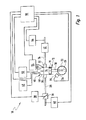
- an internal combustion engine carries this overall Reference numeral 10. It comprises an engine block with several Cylinders, only one of which is shown in FIG. 1, which bears the reference number 12.
- a combustion chamber 14 is present, which is partially from a Piston 16 is limited. This is with a connecting rod 18 a crankshaft 20 connected.
- a gearwheel 22 is in turn on the crankshaft 20 attached. It has a total of 58 Teeth (without reference numerals). Over a circumference, which corresponds to two teeth, there are no teeth. This gap on the circumference of the gear 22 bears in FIG. 1 reference numeral 24.
- An inductive sensor 26 is for Gear 22 arranged adjacent and designed so that he sweeps past when the gear 22 rotates the gap 24 can capture.
- the combustion chamber 14 is combustion air through a Inlet pipe 28 and an inlet valve 30 supplied.
- the Combustion gases are discharged from the combustion chamber 14 Exhaust valve 32 and an exhaust pipe 34 discharged.
- a Throttle valve 36 allows the amount of air to be adjusted, which through the inlet pipe 28 into the combustion chamber 14 arrives.
- the movement of the throttle valve 36 takes place through a servomotor 38.
- the one entering the combustion chamber 14 Air volume is measured by a hot film sensor (“HFM sensor") measured, which bears the reference numeral 40.
- HFM sensor hot film sensor
- a catalyst 42 is arranged, and the Mixture composition is generated by a lambda probe 44 detected.
- Fuel is the combustion chamber 14 from one in Fig. 1 only Fuel system 46 shown symbolically. On such fuel system 46 can be a fuel tank, an electric feed pump and a mechanical one Include main feed pump. This also includes Fuel system 46 a fuel rail called a "rail", in which the fuel is under high pressure is saved. An injection valve 48 is connected to this connected, which the fuel directly into the Injects combustion chamber 14 of internal combustion engine 10. The Ignition of the air-fuel mixture present in the combustion chamber 14 is done by a spark plug 50 by a Ignition system 52 is supplied with the required energy.
- Knock sensor 54 detects a possibly in combustion chamber 14 knocking combustion taking place.
- Control and regulating device 56 controlled or regulated. This is on the output side with the ignition system 52, the Injector 48, and the actuator 38 of the throttle valve 36 connected, and on the input side is the control and Control device 56 with knock sensor 54, lambda sensor 44, the inductive sensor 26 and the HFM sensor 40.
- the fuel in the Combustion chamber 14 is injected directly from injection valve 48.
- the internal combustion engine 10 can be in different Operating modes, depending on e.g. speed and torque, operate. For example, it is possible to run fuel during to inject the suction stroke into the combustion chamber 14, that is during a period in which the intake valve 30 is open. In this case the fuel builds up with the air in the combustion chamber 14 in Essentially homogeneous air / fuel mixture. Such Injection is referred to as “homogeneous injection” corresponding operating mode as “homogeneous”.
- the operations required in an operating mode Calculations and the generation of corresponding control signals are controlled by a microprocessor in the control unit 56 processed within a processing grid.
- a microprocessor in the control unit 56 processed within a processing grid.
- time-synchronous processing grids in which certain operations in certain constant temporal Intervals are done.
- Other operations are in one synchronized with the angle of rotation of the crankshaft 20 Processing grid carried out.
- the current angular position of the crankshaft 20 becomes from the inductive sensor 26 via the detection of the gap 24 and the subsequent number of teeth on the gear 22 detected.
- a Hall sensor can also be used.
- the Angular position of the crankshaft 20 is the control and Control device 56 is thus known. It is in "degrees before top dead center ignition "(vZOT) of the piston 16 measured and is plotted in Fig. 2 on the lower abscissa.
- the Intake valve 30 and exhaust valve 32 are mechanical via the camshaft (not shown) with the Crankshaft 20 rigidly connected.
- the opening period of the Exhaust valve 32 bears the reference number 58 in FIG. 2, whereas the opening period of the intake valve 30 in 2 is designated by the reference number 60.
- the gap 24 on the gear 22 defines the beginning of a first synchronize with the angle of rotation of the crankshaft 20 Processing pattern.
- This is shown in FIG. 2 as "SYNCHRO1" designated and plotted as the middle abscissa in Fig. 2.
- the start is due to construction and measurement reasons of this first processing grid at 72 ° BTDC.
- SYNCHRO1 are for a Operations required to perform homogeneous injection.
- the operations performed in SYNCHRO1 include Detection of those relevant for homogeneous injection Air filling (reference number 62), the calculation of the corresponding amount of fuel for homogeneous injection (Reference numeral 64) and the control of the injection valve 48 for performing homogeneous injection (Reference numeral 66).
- one Layer injection is a separate, second, also for Angle of rotation of the crankshaft 20 synchronous Processing grid provided.
- This is called “SYNCHRO2" is designated and is in Fig. 2 on the top abscissa applied.
- This second processing grid SYNCHRO2 starts at 132 ° VZOT.
- Immediately after the start of the second Processing grid SYNCHRO2 is the one for Stratified injection calculated fuel quantity (Reference numeral 68).
- the relevant air filling was recorded shortly before (reference numeral 70).
- the injection valve 48 is actuated immediately after calculating 68 the amount of fuel and is by the reference numeral 72.
- the control of the Ignition system 52 again takes place in the first Processing grid SYNCHRO1.
- the ignition takes place immediately after injection 72 for the Layer injection and bears the reference number 74.
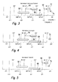
- the embodiment 10 is the internal combustion engine in the Operating mode homogeneous / shift operated. This means that one during a work cycle Homogeneous injection 66 and also one Layer injection 72 is performed. But is possible also an operating mode "homogeneous", in which exclusively homogeneous injection takes place. This is in Fig. 4 shown. Also an operating mode "shift” in which only a layer injection takes place possible. It is shown in FIG. 5.
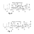
- An operating mode "shift / heating” is also possible.
- the catalytic converter 42 is switched on for a correct functioning required operating temperature brought.
- a Layer injection 76 triggered, which simultaneously with the calculation 68 of the fuel quantity for the Layer injection 72 is calculated in point 78.
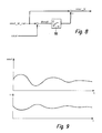
- nmot_bi_roh Immediately before the start of the second processing grid SYNCRHO2 becomes a current speed value nmot_bi_roh certainly.
- This speed value is determined by the fact that the time is measured, which, for example, three teeth of the Gear 22 immediately before the start of the second Processing grid SYNCHRO2 need to be on inductive sensor 26 to move past.
- This momentary Speed value nmot_bi_roh is therefore a "microscopic" Speed value, which still with the accelerations and Braking of the crankshaft 20 is affected, which before and after combustion in a cylinder 12 the Internal combustion engine 10 occur on the crankshaft 20.
- nmot_bi determines which of these rotational irregularities are free the mean speed nmot is also determined, which during a period of half a revolution of the Crankshaft 20 before the start of the second processing grid SYNCHRO2 ruled. Then the difference between the current speed value nmot_bi_roh and the mean Speed nmot formed. The difference value dnmot becomes one Filter supplied, which in FIG. 8 is the reference symbol 80 wearing. The resulting value becomes the current speed value nmot_bi_roh added. The now resulting adjusted instantaneous speed nmot_bi then becomes Determination 68 of the fuel quantity of the stratified injection 62 used.
Landscapes
- Engineering & Computer Science (AREA)
- Chemical & Material Sciences (AREA)
- Combustion & Propulsion (AREA)
- Mechanical Engineering (AREA)
- General Engineering & Computer Science (AREA)
- Electrical Control Of Air Or Fuel Supplied To Internal-Combustion Engine (AREA)
- Combined Controls Of Internal Combustion Engines (AREA)
- Electrical Control Of Ignition Timing (AREA)
- Combustion Methods Of Internal-Combustion Engines (AREA)
Abstract
Description
- Figur 1
- eine Prinzipdarstellung einer Brennkraftmaschine;
- Figur 2
- ein Diagramm, in dem ein erstes Verarbeitungsraster und ein zweites Verarbeitungsraster und die in den jeweiligen Verarbeitungsrastern ausgeführten Operationen über dem Drehwinkel einer Kurbelwelle der Brennkraftmaschine von Fig. 1 aufgetragen sind, wobei sich die Brennkraftmaschine in einer ersten Betriebsart befindet;
- Figur 3
- eine zu Fig. 2 leicht abgewandelte Darstellung der Verarbeitungsraster und der entsprechenden Operationen, wobei sich die Brennkraftmaschine ebenfalls in der ersten Betriebsart befindet;
- Figur 4
- eine Darstellung ähnlich wie Fig. 3, wobei sich die Brennkraftmaschine in einer zweiten Betriebsart befindet;
- Figur 5
- eine Darstellung ähnlich wie Fig. 3, wobei sich die Brennkraftmaschine in einer dritten Betriebsart befindet;
- Figur 6
- eine Darstellung ähnlich wie Fig. 3, wobei sich die Brennkraftmaschine in einer vierten Betriebsart befindet;
- Figur 7
- eine Darstellung ähnlich wie Fig. 3, wobei sich die Brennkraftmaschine in einer fünften Betriebsart befindet;
- Figur 8
- ein Ablaufschema, aus dem die Berechnung einer bereinigten Momentandrehzahl hervorgeht; und
- Figur 9
- ein Diagramm, in dem einerseits der Verlauf einer Drehzahl der Brennkraftmaschine von Fig. 1 über der Zeit und andererseits die eingespritzte Kraftstoffmenge über der Zeit dargestellt sind.
Claims (11)
- Verfahren zum Betreiben einer Brennkraftmaschine (10), bei dem mindestens ein Teil des Kraftstoffs so in mindestens einen Brennraum (14) der Brennkraftmaschine (10) eingespritzt werden kann, dass er dort geschichtet vorliegt ("Schichteinspritzung"), und bei dem für den Betrieb der Brennkraftmaschine (10) erforderliche Operationen (62-66) in einem zum Drehwinkel (vZOT) einer Kurbelwelle (20) synchronen Verarbeitungsraster (SYNCHRO1 bestimmt werden, dadurch gekennzeichnet, dass die Kraftstoffmenge der Schichteinspritzung (72) am Anfang eines eigenen, zweiten, zum Drehwinkel (vZOT) der Kurbelwelle (20) synchronen Verarbeitungsrasters (SYNCHRO2) bestimmt wird (68).
- Verfahren nach Anspruch 1, dadurch gekennzeichnet, dass mindestens ein erstes Verarbeitungsraster (SYNCHRO1) im Bereich eines Drehwinkels (vZOT) der Kurbelwelle (20) von 67° bis 77° vZOT, vorzugsweise bei ungefähr 72° vZOT, beginnt, und dass das zweite Verarbeitungsraster (SYNCHRO2), in dem die Kraftstoffmenge der Schichteinspritzung (72) bestimmt wird (68), im Bereich eines Drehwinkels (vZOT) der Kurbelwelle (20) von 127° bis 137° vZOT, vorzugsweise bei ungefähr 132° vZOT beginnt.
- Verfahren nach einem der Ansprüche 1 oder 2, dadurch gekennzeichnet, dass ein momentaner Drehzahlwert (nmot_bi_roh) unmittelbar vor Beginn des zweiten Verarbeitungsrasters (SYNCHRO2) ermittelt und für die Bestimmung (68) der Kraftstoffmenge der Schichteinspritzung (72) verwendet wird.
- Verfahren nach Anspruch 3, dadurch gekennzeichnet, dass eine mittlere Drehzahl (nmot) ermittelt wird, welche während eines Zeitraums einer halben Umdrehung der Kurbelwelle (20) vor Beginn des zweiten Verarbeitungsrasters (SYNCHRO2) geherrscht hat, dass die Differenz (dnmot) zwischen dem momentanen Drehzahlwert (nmot_bi_roh) und der mittleren Drehzahl (nmot) gebildet wird, dass diese Differenz (dnmot) einem Filter (80) oder einer Kennlinie zugeführt wird, dass der hieraus hervorgehende Wert zu dem momentanen Drehzahlwert (nmot_bi_roh) addiert wird, und dass die hieraus hervorgehende bereinigte Momentandrehzahl (nmot_bi) zur Bestimmung (68) der Kraftstoffmenge der Schichteinspritzung (72) verwendet wird.
- Verfahren nach Anspruch 4, dadurch gekennzeichnet, dass die bereinigte Momentandrehzahl (nmot_bi) mit einer zuvor ermittelten bereinigten Momentandrehzahl (nmot_bi) verglichen und hieraus im zweiten Verarbeitungsraster (SYNCHRO2) die Kraftstoffmenge der Schichteinspritzung (72) so bestimmt wird (68), dass Schwankungen der mittleren Drehzahl (nmot) unterdrückt werden.
- Verfahren nach einem der vorhergehenden Ansprüche, dadurch gekennzeichnet, dass auch die Luftmenge, welche bei der Bestimmung (68) der Kraftstoffmenge der Schichteinspritzung (72) berücksichtigt wird, im zweiten Verarbeitungsraster (SYNCHRO2), vorzugsweise unmittelbar vor der Berechnung (68) der Kraftstoffmenge der Schichteinspritzung (72), bestimmt wird (70).
- Verfahren nach einem der vorhergehenden Ansprüche, dadurch gekennzeichnet, dass mindestens ein Teil des Kraftstoffs so in einen Brennraum (14) der Brennkraftmaschine (10) eingespritzt wird (66), dass er dort im Wesentlichen homogen vorliegt ("Homogeneinspritzung"), und die Kraftstoffmenge der Homogeneinspritzung (66) am Anfang des ersten Verarbeitungsrasters (SYNCHRO1) bestimmt wird (64).
- Verfahren nach einem der vorhergehenden Ansprüche, dadurch gekennzeichnet, dass der Zeitpunkt der Zündung (74) im ersten Verarbeitungsraster (SYNCHRO1) bestimmt wird.
- Computerprogramm, dadurch gekennzeichnet, dass es zur Durchführung des Verfahrens nach einem der vorhergehenden Ansprüche geeignet ist, wenn es auf einem Computer ausgeführt wird.
- Computerprogramm nach Anspruch 9, dadurch gekennzeichnet, dass es auf einem Speicher, insbesondere auf einem Flash-Memory, abgespeichert ist.
- Steuer- und/oder Regelgerät (56) zum Betreiben einer Brennkraftmaschine (10), dadurch gekennzeichnet, dass es einen Speicher umfasst, auf dem ein Computerprogramm nach einem der Ansprüche 9 oder 10 abgespeichert ist.
Applications Claiming Priority (2)
| Application Number | Priority Date | Filing Date | Title |
|---|---|---|---|
| DE10139518 | 2001-08-10 | ||
| DE10139518A DE10139518A1 (de) | 2001-08-10 | 2001-08-10 | Verfahren, Computerprogramm und Steuer- und/oder Regelgerät zum Betreiben einer Brennkraftmaschine |
Publications (3)
| Publication Number | Publication Date |
|---|---|
| EP1283343A2 true EP1283343A2 (de) | 2003-02-12 |
| EP1283343A3 EP1283343A3 (de) | 2006-02-01 |
| EP1283343B1 EP1283343B1 (de) | 2007-04-11 |
Family
ID=7695148
Family Applications (1)
| Application Number | Title | Priority Date | Filing Date |
|---|---|---|---|
| EP02016003A Expired - Lifetime EP1283343B1 (de) | 2001-08-10 | 2002-07-18 | Verfahren, Computerprogramm und Steuer- und/oder Regelgerät zum Betreiben einer Brennkraftmaschine |
Country Status (4)
| Country | Link |
|---|---|
| EP (1) | EP1283343B1 (de) |
| JP (1) | JP2003106183A (de) |
| DE (2) | DE10139518A1 (de) |
| ES (1) | ES2284753T3 (de) |
Cited By (2)
| Publication number | Priority date | Publication date | Assignee | Title |
|---|---|---|---|---|
| WO2008142549A1 (en) * | 2007-05-23 | 2008-11-27 | Toyota Jidosha Kabushiki Kaisha | Internal combustion engine control apparatus and method |
| DE102007063101A1 (de) | 2007-12-28 | 2009-07-02 | Robert Bosch Gmbh | Verfahren zum Betreiben einer Brennkraftmaschine |
Families Citing this family (1)
| Publication number | Priority date | Publication date | Assignee | Title |
|---|---|---|---|---|
| US7779810B2 (en) * | 2006-09-13 | 2010-08-24 | Gm Global Technology Operations, Inc. | Idle stability improvement for direct injected engines |
Citations (1)
| Publication number | Priority date | Publication date | Assignee | Title |
|---|---|---|---|---|
| DE19851974A1 (de) | 1998-11-03 | 2000-05-04 | Bosch Gmbh Robert | Verfahren und Vorrichtung zur Steuerung von Betriebsabläufen in einem Fahrzeug |
Family Cites Families (3)
| Publication number | Priority date | Publication date | Assignee | Title |
|---|---|---|---|---|
| JPH0765540B2 (ja) * | 1988-09-21 | 1995-07-19 | 松下電器産業株式会社 | エンジン制御装置 |
| JP3680492B2 (ja) * | 1997-06-03 | 2005-08-10 | 日産自動車株式会社 | 内燃機関の制御装置 |
| DE19751887A1 (de) * | 1997-11-22 | 1999-07-29 | Bosch Gmbh Robert | Verfahren zum Betreiben einer Brennkraftmaschine insbesondere eines Kraftfahrzeugs |
-
2001
- 2001-08-10 DE DE10139518A patent/DE10139518A1/de not_active Ceased
-
2002
- 2002-07-18 EP EP02016003A patent/EP1283343B1/de not_active Expired - Lifetime
- 2002-07-18 ES ES02016003T patent/ES2284753T3/es not_active Expired - Lifetime
- 2002-07-18 DE DE50209898T patent/DE50209898D1/de not_active Expired - Lifetime
- 2002-08-08 JP JP2002231878A patent/JP2003106183A/ja active Pending
Patent Citations (1)
| Publication number | Priority date | Publication date | Assignee | Title |
|---|---|---|---|---|
| DE19851974A1 (de) | 1998-11-03 | 2000-05-04 | Bosch Gmbh Robert | Verfahren und Vorrichtung zur Steuerung von Betriebsabläufen in einem Fahrzeug |
Cited By (4)
| Publication number | Priority date | Publication date | Assignee | Title |
|---|---|---|---|---|
| WO2008142549A1 (en) * | 2007-05-23 | 2008-11-27 | Toyota Jidosha Kabushiki Kaisha | Internal combustion engine control apparatus and method |
| US7853399B2 (en) | 2007-05-23 | 2010-12-14 | Toyota Jidosha Kabushiki Kaisha | Internal combustion engine control apparatus and method |
| DE102007063101A1 (de) | 2007-12-28 | 2009-07-02 | Robert Bosch Gmbh | Verfahren zum Betreiben einer Brennkraftmaschine |
| WO2009083470A1 (de) * | 2007-12-28 | 2009-07-09 | Robert Bosch Gmbh | Verfahren zum betreiben einer brennkraftmaschine |
Also Published As
| Publication number | Publication date |
|---|---|
| JP2003106183A (ja) | 2003-04-09 |
| DE10139518A1 (de) | 2003-03-06 |
| EP1283343A3 (de) | 2006-02-01 |
| DE50209898D1 (de) | 2007-05-24 |
| ES2284753T3 (es) | 2007-11-16 |
| EP1283343B1 (de) | 2007-04-11 |
Similar Documents
| Publication | Publication Date | Title |
|---|---|---|
| DE69830818T2 (de) | Übergangsregelsystem zwischen zwei funkengezündeten Brennzuständen in einem Motor | |
| DE3918772C2 (de) | ||
| DE102012208337B4 (de) | Verfahren zum steuern eines mit einer kraftstoffmischung aus dieselkraftstoff und biodieselkraftstoff betriebenen verbrennungsmotors | |
| DE102005018599A1 (de) | Vorrichtung und Verfahren zum Steuern der Kraftstoffeinspritzung in einem Verbrennungsmotor | |
| DE19739786A1 (de) | System und Verfahren zur Kraftstoffeinspritzsteuerung in Benzinmotoren mit Direkteinspritzung | |
| DE3423144A1 (de) | Verfahren zum steuern der kraftstoffzufuhr zu einer brennkraftmaschine bei beschleunigung | |
| DE19623151A1 (de) | Kraftstoffeinspritzsteuervorrichtung eines mehrzylindrigen Motors | |
| DE102010062132B4 (de) | Verfahren zum Reduzieren der von einem Benzinmotor erzeugten Partikelmaterie | |
| DE102008001670A1 (de) | Verfahren und Vorrichtung zum Betreiben einer Brennkraftmaschine | |
| DE10146504B4 (de) | Zündzeitpunkt-Steuervorrichtung und Zündzeitpunkt-Steuerverfahren für Verbrennungsmotoren | |
| DE102006026640A1 (de) | Verfahren zum Betreiben einer Brennkraftmaschine | |
| DE3922116A1 (de) | Verfahren und vorrichtung zur kraftstoffeinspritzung bei einer brennkraftmaschine | |
| DE102016201443B4 (de) | Motorstartsystem | |
| DE10329328B4 (de) | Verfahren zur Steuerung einer Brennkraftmaschine | |
| DE69925343T2 (de) | Kraftstoffeinspritzsteuervorrichtung für eine Brennkraftmaschine | |
| EP1431557A2 (de) | Verfahren zur Zylindergleichstellung | |
| DE3919778C2 (de) | ||
| DE69916464T2 (de) | Verfahren zum reduzieren der kaltstartemissionen bei brennkraftmaschinen | |
| DE102005014920A1 (de) | Verfahren zur zylinderindividuellen Einstellung von Einspritzzeiten einer Verbrennungskraftmaschine | |
| DE3702500A1 (de) | Kraftstoffeinspritz-verstellsteuerverfahren fuer brennkraftmaschinen | |
| DE102011004068B3 (de) | Verfahren und Steuervorrichtung zum Gleichstellen mehrerer Zylinder einer Brennkraftmaschine | |
| DE19958465C2 (de) | Verfahren zum Betreiben einer Brennkraftmaschine | |
| DE10033946B4 (de) | Kraftstoffeinspritzsteuersystem für eine Brennkraftmaschine mit Direkteinspritzung | |
| EP1283343B1 (de) | Verfahren, Computerprogramm und Steuer- und/oder Regelgerät zum Betreiben einer Brennkraftmaschine | |
| DE19517767C2 (de) | Kraftstoffeinspritz-Steuersystem für eine Brennkraftmaschine |
Legal Events
| Date | Code | Title | Description |
|---|---|---|---|
| PUAI | Public reference made under article 153(3) epc to a published international application that has entered the european phase |
Free format text: ORIGINAL CODE: 0009012 |
|
| AK | Designated contracting states |
Designated state(s): AT BE BG CH CY CZ DE DK EE ES FI FR GB GR IE IT LI LU MC NL PT SE SK TR |
|
| AX | Request for extension of the european patent |
Extension state: AL LT LV MK RO SI |
|
| PUAL | Search report despatched |
Free format text: ORIGINAL CODE: 0009013 |
|
| AK | Designated contracting states |
Kind code of ref document: A3 Designated state(s): AT BE BG CH CY CZ DE DK EE ES FI FR GB GR IE IT LI LU MC NL PT SE SK TR |
|
| AX | Request for extension of the european patent |
Extension state: AL LT LV MK RO SI |
|
| 17P | Request for examination filed |
Effective date: 20060801 |
|
| AKX | Designation fees paid |
Designated state(s): DE ES FR IT |
|
| GRAP | Despatch of communication of intention to grant a patent |
Free format text: ORIGINAL CODE: EPIDOSNIGR1 |
|
| GRAS | Grant fee paid |
Free format text: ORIGINAL CODE: EPIDOSNIGR3 |
|
| GRAA | (expected) grant |
Free format text: ORIGINAL CODE: 0009210 |
|
| AK | Designated contracting states |
Kind code of ref document: B1 Designated state(s): DE ES FR IT |
|
| REF | Corresponds to: |
Ref document number: 50209898 Country of ref document: DE Date of ref document: 20070524 Kind code of ref document: P |
|
| ET | Fr: translation filed | ||
| REG | Reference to a national code |
Ref country code: ES Ref legal event code: FG2A Ref document number: 2284753 Country of ref document: ES Kind code of ref document: T3 |
|
| PLBE | No opposition filed within time limit |
Free format text: ORIGINAL CODE: 0009261 |
|
| STAA | Information on the status of an ep patent application or granted ep patent |
Free format text: STATUS: NO OPPOSITION FILED WITHIN TIME LIMIT |
|
| 26N | No opposition filed |
Effective date: 20080114 |
|
| PGFP | Annual fee paid to national office [announced via postgrant information from national office to epo] |
Ref country code: ES Payment date: 20090724 Year of fee payment: 8 |
|
| PGFP | Annual fee paid to national office [announced via postgrant information from national office to epo] |
Ref country code: IT Payment date: 20090730 Year of fee payment: 8 |
|
| PG25 | Lapsed in a contracting state [announced via postgrant information from national office to epo] |
Ref country code: IT Free format text: LAPSE BECAUSE OF NON-PAYMENT OF DUE FEES Effective date: 20100718 |
|
| REG | Reference to a national code |
Ref country code: ES Ref legal event code: FD2A Effective date: 20110818 |
|
| PG25 | Lapsed in a contracting state [announced via postgrant information from national office to epo] |
Ref country code: ES Free format text: LAPSE BECAUSE OF NON-PAYMENT OF DUE FEES Effective date: 20100719 |
|
| PGFP | Annual fee paid to national office [announced via postgrant information from national office to epo] |
Ref country code: FR Payment date: 20140724 Year of fee payment: 13 |
|
| REG | Reference to a national code |
Ref country code: FR Ref legal event code: ST Effective date: 20160331 |
|
| PG25 | Lapsed in a contracting state [announced via postgrant information from national office to epo] |
Ref country code: FR Free format text: LAPSE BECAUSE OF NON-PAYMENT OF DUE FEES Effective date: 20150731 |
|
| PGFP | Annual fee paid to national office [announced via postgrant information from national office to epo] |
Ref country code: DE Payment date: 20160927 Year of fee payment: 15 |
|
| REG | Reference to a national code |
Ref country code: DE Ref legal event code: R119 Ref document number: 50209898 Country of ref document: DE |
|
| PG25 | Lapsed in a contracting state [announced via postgrant information from national office to epo] |
Ref country code: DE Free format text: LAPSE BECAUSE OF NON-PAYMENT OF DUE FEES Effective date: 20180201 |