EP1283349B1 - Einströmtür für einen Luftreiniger - Google Patents
Einströmtür für einen Luftreiniger Download PDFInfo
- Publication number
- EP1283349B1 EP1283349B1 EP20020252494 EP02252494A EP1283349B1 EP 1283349 B1 EP1283349 B1 EP 1283349B1 EP 20020252494 EP20020252494 EP 20020252494 EP 02252494 A EP02252494 A EP 02252494A EP 1283349 B1 EP1283349 B1 EP 1283349B1
- Authority
- EP
- European Patent Office
- Prior art keywords
- door
- air cleaner
- cam
- sidewall
- solenoid assembly
- Prior art date
- Legal status (The legal status is an assumption and is not a legal conclusion. Google has not performed a legal analysis and makes no representation as to the accuracy of the status listed.)
- Expired - Lifetime
Links
Images



Classifications
-
- F—MECHANICAL ENGINEERING; LIGHTING; HEATING; WEAPONS; BLASTING
- F02—COMBUSTION ENGINES; HOT-GAS OR COMBUSTION-PRODUCT ENGINE PLANTS
- F02M—SUPPLYING COMBUSTION ENGINES IN GENERAL WITH COMBUSTIBLE MIXTURES OR CONSTITUENTS THEREOF
- F02M35/00—Combustion-air cleaners, air intakes, intake silencers, or induction systems specially adapted for, or arranged on, internal-combustion engines
- F02M35/10—Air intakes; Induction systems
- F02M35/10242—Devices or means connected to or integrated into air intakes; Air intakes combined with other engine or vehicle parts
- F02M35/10301—Flexible, resilient, pivotally or movable parts; Membranes
-
- F—MECHANICAL ENGINEERING; LIGHTING; HEATING; WEAPONS; BLASTING
- F02—COMBUSTION ENGINES; HOT-GAS OR COMBUSTION-PRODUCT ENGINE PLANTS
- F02M—SUPPLYING COMBUSTION ENGINES IN GENERAL WITH COMBUSTIBLE MIXTURES OR CONSTITUENTS THEREOF
- F02M23/00—Apparatus for adding secondary air to fuel-air mixture
- F02M23/04—Apparatus for adding secondary air to fuel-air mixture with automatic control
-
- F—MECHANICAL ENGINEERING; LIGHTING; HEATING; WEAPONS; BLASTING
- F02—COMBUSTION ENGINES; HOT-GAS OR COMBUSTION-PRODUCT ENGINE PLANTS
- F02M—SUPPLYING COMBUSTION ENGINES IN GENERAL WITH COMBUSTIBLE MIXTURES OR CONSTITUENTS THEREOF
- F02M35/00—Combustion-air cleaners, air intakes, intake silencers, or induction systems specially adapted for, or arranged on, internal-combustion engines
- F02M35/02—Air cleaners
-
- F—MECHANICAL ENGINEERING; LIGHTING; HEATING; WEAPONS; BLASTING
- F02—COMBUSTION ENGINES; HOT-GAS OR COMBUSTION-PRODUCT ENGINE PLANTS
- F02M—SUPPLYING COMBUSTION ENGINES IN GENERAL WITH COMBUSTIBLE MIXTURES OR CONSTITUENTS THEREOF
- F02M35/00—Combustion-air cleaners, air intakes, intake silencers, or induction systems specially adapted for, or arranged on, internal-combustion engines
- F02M35/10—Air intakes; Induction systems
- F02M35/10006—Air intakes; Induction systems characterised by the position of elements of the air intake system in direction of the air intake flow, i.e. between ambient air inlet and supply to the combustion chamber
- F02M35/10013—Means upstream of the air filter; Connection to the ambient air
-
- Y—GENERAL TAGGING OF NEW TECHNOLOGICAL DEVELOPMENTS; GENERAL TAGGING OF CROSS-SECTIONAL TECHNOLOGIES SPANNING OVER SEVERAL SECTIONS OF THE IPC; TECHNICAL SUBJECTS COVERED BY FORMER USPC CROSS-REFERENCE ART COLLECTIONS [XRACs] AND DIGESTS
- Y02—TECHNOLOGIES OR APPLICATIONS FOR MITIGATION OR ADAPTATION AGAINST CLIMATE CHANGE
- Y02T—CLIMATE CHANGE MITIGATION TECHNOLOGIES RELATED TO TRANSPORTATION
- Y02T10/00—Road transport of goods or passengers
- Y02T10/10—Internal combustion engine [ICE] based vehicles
- Y02T10/12—Improving ICE efficiencies
-
- Y—GENERAL TAGGING OF NEW TECHNOLOGICAL DEVELOPMENTS; GENERAL TAGGING OF CROSS-SECTIONAL TECHNOLOGIES SPANNING OVER SEVERAL SECTIONS OF THE IPC; TECHNICAL SUBJECTS COVERED BY FORMER USPC CROSS-REFERENCE ART COLLECTIONS [XRACs] AND DIGESTS
- Y10—TECHNICAL SUBJECTS COVERED BY FORMER USPC
- Y10S—TECHNICAL SUBJECTS COVERED BY FORMER USPC CROSS-REFERENCE ART COLLECTIONS [XRACs] AND DIGESTS
- Y10S55/00—Gas separation
- Y10S55/28—Carburetor attached
-
- Y—GENERAL TAGGING OF NEW TECHNOLOGICAL DEVELOPMENTS; GENERAL TAGGING OF CROSS-SECTIONAL TECHNOLOGIES SPANNING OVER SEVERAL SECTIONS OF THE IPC; TECHNICAL SUBJECTS COVERED BY FORMER USPC CROSS-REFERENCE ART COLLECTIONS [XRACs] AND DIGESTS
- Y10—TECHNICAL SUBJECTS COVERED BY FORMER USPC
- Y10T—TECHNICAL SUBJECTS COVERED BY FORMER US CLASSIFICATION
- Y10T137/00—Fluid handling
- Y10T137/7722—Line condition change responsive valves
- Y10T137/7748—Combustion engine induction type
- Y10T137/7749—Valve in auxiliary inlet to induction line
Definitions
- the invention relates generally to the field of air cleaners.
- this invention relates to an air cleaner intake door for automotive vehicles.
- Combustion engines require a regular supply of air in order to operate.
- An engine can generate increased power as long as the supply of air can be increased.
- Air is supplied to the engine via air intakes.
- a filter In a standard air intake, a filter is typically used to screen out any debris that could enter the engine and cause damage to it.
- An air cleaner normally has one intake for dirty air, through which outside air enters. The outside air is drawn through an enclosed passage through a filter and into the engine, where it is mixed with fuel in the engine induction system. If the opening or passage of an air cleaner becomes blocked, the air supply to the engine will be cut off or greatly reduced, resulting in stalling or decreased engine power. Leaves or other roadside debris often cause such blockage. The air intake could also become blocked or otherwise cut off by being immersed in water if a car passes through deep standing water.
- Patent No US 6,209,503 relates to an air cleaner having a secondary intake door which has a cam and a spring which is opened by suction air pressure to supply the engine with additional intake air when required.
- Patent Application No DE 41 33 815 relates to an air cleaner having a secondary air inlet, and in which the primary or secondary air inlet may be closed in dependence upon the speed of the internal combustion engine.
- an air cleaner having a secondary air intake door comprising: an air cleaner having at least one sidewall, said sidewall defining at least one opening therethrough; a primary air intake a secondary air intake door mounted over said opening adjacent to said at least one sidewall and rotationally movable between an open position and a closed position over said opening; a cam extending from said door; and a spring in contact with said cam for biasing said door towards a closed position over said opening characterised in that the air cleaner further comprises a solenoid assembly with a movable shaft, said solenoid assembly attached to said sidewall of said air cleaner so as to allow said movable shaft to move into contact with said cam.
- a method for supplying a secondary air intake on an air cleaner comprising a door with an attached cam mounted on said air cleaner intake by an axle; a solenoid assembly with a movable shaft; and a spring attached to said axle; said method comprising the steps of: moving said movable shaft when the solenoid assembly is activated such that said cam contacts with said movable shaft to open said door; closing said door by applying pressure to said cam from said spring when the solenoid assembly is not activated unless said pressure is overcome by vacuum pressure, thus allowing the door to open.
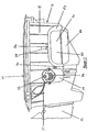
- an air cleaner 10 utilizing the intake door of the present invention is shown.
- the air cleaner 10 has a primary air intake 12 on one side thereof. Air flows through the primary air intake 12, into the air cleaner 10, and continues through a filter (not shown) on the top side 14 of the air cleaner 10 to the engine where it mixes with fuel.
- a door 16 is preferably provided on a sidewall 18 of the air cleaner 10 to provide a secondary air intake.
- An opening in the sidewall 18 forms the secondary air intake.
- the door 16 is shown from its first side 20.
- the door 16 is positioned over the opening in the sidewall 18.
- the door 16 preferably includes a flap 22 that contacts the sidewall 18 of the air cleaner 10 when the door 16 is in its closed position as shown in FIGS. 1-3.
- the contact between the flap 22 and the sidewall 18 of the air cleaner 10 prevents the door 16 from rotating outwardly from the air cleaner 10.
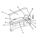
- Figure 7 shows the door 16 in an open position and the flap 22 out of contact with the sidewall 18 of the air cleaner 10.
- a bellmouth 24 extends from the sidewall 18 of the air cleaner 10.
- the bellmouth 24 increases the amount of air that may enter the intake, thus increasing efficiency.
- the bellmouth 24 may be attached to the sidewall 18 of the air cleaner 10 via a plurality of clips 26, allowing for easy removal if necessary.
- a housing 28 is preferably positioned on the sidewall 18 of the air cleaner 10 to hold a solenoid assembly 30.
- the solenoid assembly 30 is operatively connected to an actuated shaft 32, which is movable in response to the activation of the solenoid assembly 30.
- the solenoid assembly 30 is preferably connected to a circuit via wires 34 running to a control system that can activate the solenoid assembly 30 depending on the requirements of the engine.
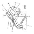
- the second side 36 of the door 16 is shown from the interior of the air cleaner 10.
- the bellmouth 24 could be attached to the air cleaner 10 in any number of ways. One example would be to provide clips 26 to hold the bellmouth 24 in place. The clips 26 protrude into the interior of the air cleaner 10 through holes 38 defined in the sidewall 18 of the air cleaner 10. The bellmouth 24 could also be welded in place or attached with an adhesive.
- the housing 28 for the solenoid assembly 30 also protrudes into the interior of the air cleaner 10.
- the tip 40 of the actuated shaft 32 of the solenoid assembly 30 is shown in FIG. 4 in its first position.
- the door 16 is preferably rotationally connected to the air cleaner 10 by an axle 42.
- the axle 42 allows the door 16 to pivot from an open to a closed position.
- a cam extension 44 preferably extends from one side of the door 16.
- the cam extension 44 is preferably located on the interior of the air cleaner 10 and is shown in the figures as being continuous with the door 16.
- the cam extension 44 preferably extends parallel to the sidewall 18 of the air cleaner 10.
- the cam extension 44 preferably has a bent section 46 forming a ledge 48 that is substantially aligned with the actuated shaft 32 of the solenoid assembly 30.
- the cam extension 44 is preferably not physically connected to the actuated shaft 32.
- a coiled spring 50 has a main body preferably wrapped around the axle 42 and preferably has two extensions 52 to provide opposing biasing force.
- One extension 52 is in contact with the sidewall 18 of the air cleaner 10, and the other extension 52 is in contact with the cam extension 44.
- the extensions 52 provide rotational resistance to the cam extension 44, preventing the door 16 from opening without sufficient force.
- the spring 50 also acts to return the door 16 to a closed position. Other embodiments of the spring 50 could be utilized to provide the appropriate biasing force.
- the operation of the door 16 is as follows. There are two methods of opening the door 16 in the invention provided.
- the first method acts as a fail-safe mechanism to allow the door 16 to open when the primary air intake 12 is blocked.
- the first method acts as a fail-safe mechanism to allow the door 16 to open when the primary air intake 12 is blocked.
- the vacuum pressure on the inside of the air cleaner 10 will increase due to the suction of the engine intake manifold.
- the spring 50 and the extensions 52 on the axle 42 of the door 16 are preferably calibrated to withstand a certain amount of pull from vacuum pressure in the manifold.
- a typical vacuum level that would cause the door 16 to open would be 1kPa or an opening force of 50N. Of course, other levels than those specified may be utilized without departing from the present invention.
- a blockage increases the vacuum pressure past the threshold of resistance and the door 16 is pulled inwardly by the vacuum pressure, allowing air to enter the air cleaner 10 through the secondary intake. This prevents engine stalling and maintains engine power when the primary
- the second method of opening the door 16 is provided utilizing the solenoid assembly 30, the actuated shaft 32, and the cam extension 44.
- the solenoid assembly 30 is controlled by a circuit connected to an engine control system (not shown).
- the connection in the Figures is shown as a pair of wires 34, but the connection could be accomplished in any manner known in the art.
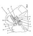
- the actuated shaft 32 is normally in a first position as shown in FIG. 5 when the solenoid assembly 30 is deactivated.
- the actuated shaft 32 moves to its second position as shown in FIG. 6 and protrudes further into the air cleaner 10. This movement causes the tip 40 of the actuated shaft 32 to come into contact with the ledge 48 of the cam extension 44.
- the tip 40 of the actuated shaft 32 may be a low friction material to reduce wear on the ledge 48 of the cam extension 44.
- the pressure from the actuated shaft 32 against the ledge 48 of the cam extension 44 causes the door 16 to rotate into the interior of the air cleaner 10.
- an internal spring (not shown) returns the actuated shaft 32 to its first position, and the pressure on the cam extension 44 from the spring 50 moves the door 16 back to its closed position.
- Figure 5 shows the actuated shaft 32 in its first position and the door 16 in its closed position, flush against the sidewall 18 of the air cleaner 10.
- Figure 6 shows the actuated shaft 32 in its second position and the door 16 in an open position.
- Figure 7 shows the door 16 in an open position, as viewed from the outside of the air cleaner 10.
- the solenoid assembly 30 can be activated by a signal from the engine control system whenever more air is needed in the intake. For example, the solenoid assembly 30 may be activated to open the door 16 at a certain engine RPM level. This secondary air intake provided by the door 16 allows more air to enter the engine, thereby increasing engine power and output. By only allowing the door 16 to open at certain engine RPM levels, engine noise regulations can be met without necessitating extra sound-dampening measures.
- the door 16 could vary in size and shape, as could the cam extension 44 and ledge 48.
- the cam extension 44 and solenoid assembly 30 could be positioned differently.
- the solenoid assembly 30 could also be activated by other signals from the vehicle.
- the bellmouth 24 may be permanently attached to the sidewall 18 of the air cleaner 10 rather than removably attached.
- the door 16 could be relocated on a different side of the air cleaner 10, and more than one door 16 could be used on the same air cleaner 10.
Landscapes
- Engineering & Computer Science (AREA)
- Chemical & Material Sciences (AREA)
- Combustion & Propulsion (AREA)
- Mechanical Engineering (AREA)
- General Engineering & Computer Science (AREA)
- Cooling, Air Intake And Gas Exhaust, And Fuel Tank Arrangements In Propulsion Units (AREA)
- Filtering Of Dispersed Particles In Gases (AREA)
Claims (13)
- Luftreiniger (10) mit einer sekundären Lufteinlaßtür (16), der folgendes umfaßt:dadurch gekennzeichnet, daß der Luftreiniger (10) weiterhin eine an der Seitenwand (18) befestigte Solenoidbaugruppe (30) und eine von dem Solenoid betätigte Welle (32) umfaßt, die sich von der Solenoidbaugruppe aus erstreckt, damit sich die bewegliche Welle (32) so bewegen kann, daß sie mit dem Nocken (44) in Berührung kommt.mindestens eine Seitenwand (18), die mindestens eine Öffnung dort hindurch definiert,einen primären Lufteinlaß (12),eine sekundäre Lufteinlaßtür (16), die an die mindestens eine Seitenwand (18) angrenzend über der Öffnung angebracht und zwischen einer offenen Position undeiner geschlossenen Position über der Öffnung drehbar beweglich ist,einen Nocken (44), der sich von der Tür (16) aus erstreckt, undeine den Nocken (44) berührende Feder (50) für das Vorspannen der Tür (16) in eine geschlossene Position über der Öffnung,
- Luftreiniger nach Anspruch 1, der weiterhin einen an die Öffnung angrenzend außen an dem Luftreiniger an der Seitenwand (18) angebrachten Einlauftrichter (24) umfaßt.
- Luftreiniger nach Anspruch 1 oder Anspruch 2, bei dem die Tür (16) mit der Seitenwand (18) des Luftreinigers (10) abschließt, wenn sie (16) sich in der geschlossenen Position befindet.
- Luftreiniger nach einem der Ansprüche 1 bis 3, bei dem sich die Tür (16) teilweise in die Öffnung erstreckt, wenn sie (16) sich in der offenen Position befindet.
- Luftreiniger nach einem der vorhergehenden Ansprüche, bei dem sich der Nocken (44) von der Tür (16) aus parallel zur Seitenwand (18) erstreckt.
- Luftreiniger nach einem der vorhergehenden Ansprüche, bei dem die Feder (50) einen Hauptkörper und mindestens zwei Fortsätze (52) aufweist, von denen einer den Nocken (44) berührt und einer die Seitenwand (18) des Luftreinigers berührt und eine Vorspannungskraft ausübt.
- Luftreiniger nach Anspruch 6, bei dem die von der Feder (50) bereitgestellte Vorspannungskraft durch Unterdruck überwunden werden kann, wodurch die Tür (16) durch diesen Unterdruck geöffnet werden kann.
- Luftreiniger nach Anspruch 6 oder Anspruch 7, bei dem die Vorspannungskraft die Tür (16) aus ihrer offenen Position in ihre geschlossene Position vorspannt.
- Luftreiniger nach einem der vorhergehenden Ansprüche, bei dem die bewegliche Welle (32) zwischen einer ersten Position und einer zweiten Position beweglich ist.
- Luftreiniger nach Anspruch 9, bei dem die bewegliche Welle (32), wenn sie (32) sich in der zweiten Position befindet, den Nocken (44) berührt, um die Tür (16) in die offene Position zu bewegen.
- Luftreiniger nach einem der vorhergehenden Ansprüche, bei dem, wenn die Solenoidbaugruppe (30) deaktiviert wird, die Welle (32) in die erste Position zurückkehrt und die Feder (50) die Tür in die geschlossene Position bewegt.
- Verfahren für das Versorgen eines sekundären Lufteinlasses an einem Luftreiniger, der folgendes umfaßt:wobei das Verfahren folgende Schritte umfaßt:eine Tür (16) mit einem daran befestigten Nocken (44), die durch eine Achse (42) an dem Luftreinigereinlaß angebracht ist,eine Solenoidbaugruppe (30) mit einer beweglichen Welle (32) undeine an der Achse (42) befestigte Feder (50),Bewegen der beweglichen Welle (32), wenn die Solenoidbaugruppe (30) durch ein Signal von einer Antriebssteuerung aktiviert wird, so daß der Nocken (44) die bewegliche Welle (32) berührt und die Tür (16) öffnet,Schließen der Tür (16) durch Anlegen von Druck von der Feder (50) an den Nocken (44), wenn die Solenoidbaugruppe (30) nicht aktiviert ist, es sei denn, der Druck wird durch einen Unterdruck oder Vakuumdruck überwunden, wodurch sich die Tür (16) öffnen kann.
- Verfahren nach Anspruch 12, bei dem das Signal die Solenoidbaugruppe (30) bei einer bestimmten Motordrehzahl aktiviert.
Applications Claiming Priority (2)
| Application Number | Priority Date | Filing Date | Title |
|---|---|---|---|
| US09/927,838 US6726742B2 (en) | 2001-08-10 | 2001-08-10 | Air cleaner with a secondary intake |
| US927838 | 2001-08-10 |
Publications (3)
| Publication Number | Publication Date |
|---|---|
| EP1283349A2 EP1283349A2 (de) | 2003-02-12 |
| EP1283349A3 EP1283349A3 (de) | 2003-10-15 |
| EP1283349B1 true EP1283349B1 (de) | 2005-01-12 |
Family
ID=25455336
Family Applications (1)
| Application Number | Title | Priority Date | Filing Date |
|---|---|---|---|
| EP20020252494 Expired - Lifetime EP1283349B1 (de) | 2001-08-10 | 2002-04-06 | Einströmtür für einen Luftreiniger |
Country Status (3)
| Country | Link |
|---|---|
| US (1) | US6726742B2 (de) |
| EP (1) | EP1283349B1 (de) |
| DE (1) | DE60202565T2 (de) |
Families Citing this family (18)
| Publication number | Priority date | Publication date | Assignee | Title |
|---|---|---|---|---|
| US6790251B1 (en) * | 2003-01-30 | 2004-09-14 | Stephen H. Brady, Jr. | Skull-shaped air filter housing |
| US7393372B2 (en) * | 2005-02-03 | 2008-07-01 | Visteon Global Technologies, Inc. | Air cleaner for an air induction assembly having primary and secondary inlets |
| DE102005029193A1 (de) * | 2005-06-22 | 2006-12-28 | Mahle International Gmbh | Klappenanordnung für eine Frischgasanlage |
| US7459004B2 (en) * | 2005-06-23 | 2008-12-02 | Kawasaki Jukogyo Kabushiki Kaisha | Mounting structure for air cleaner |
| DE602006015503D1 (en) | 2005-10-12 | 2010-08-26 | Kohler Co | Luftreinigeranordnung |
| US7401590B2 (en) * | 2006-10-09 | 2008-07-22 | Harley-Davidson Motor Company Group, Inc. | Active air intake for an engine |
| CA2671929C (en) * | 2006-12-04 | 2013-03-19 | The Procter & Gamble Company | Absorbent articles comprising graphics |
| DE102007034518A1 (de) * | 2007-07-24 | 2009-01-29 | Dr. Ing. H.C. F. Porsche Aktiengesellschaft | Luftfilter für eine Luftsauganlage einer mehrzylindrischen Brennkraftmaschine |
| USD593190S1 (en) * | 2008-05-21 | 2009-05-26 | Liquid Combustion Technology, Llc | Air filter assembly |
| US8808432B2 (en) | 2008-06-13 | 2014-08-19 | Kohler Co. | Cyclonic air cleaner |
| USD632770S1 (en) | 2008-06-13 | 2011-02-15 | Kohler Co. | Cyclonic air cleaner housing |
| US8048179B2 (en) * | 2009-01-28 | 2011-11-01 | Mann + Hummel Gmbh | Air cleaner with snow bypass valve |
| US8043395B2 (en) * | 2009-01-28 | 2011-10-25 | Mann + Hummel Gmbh | Air cleaner convertible for secondary air induction |
| USD626642S1 (en) | 2009-03-05 | 2010-11-02 | Resmed Limited | Humidifier tub for humidifier for positive airway pressure delivery device |
| USD635245S1 (en) * | 2009-12-18 | 2011-03-29 | Resmed Limited | Humidifier tub |
| USD635244S1 (en) * | 2009-12-18 | 2011-03-29 | Resmed Limited | Humidifier tub |
| KR101449321B1 (ko) * | 2013-08-20 | 2014-10-08 | 주식회사 리한 | 차량용 에어클리너 |
| CN114485113B (zh) * | 2021-07-29 | 2023-04-07 | 黄勇 | 一种基于余热烘干的木质物脱水装置及方法 |
Family Cites Families (25)
| Publication number | Priority date | Publication date | Assignee | Title |
|---|---|---|---|---|
| US2788086A (en) * | 1952-11-15 | 1957-04-09 | Houdaille Industries Inc | Air cleaner with dual air intake |
| US3452521A (en) * | 1967-05-05 | 1969-07-01 | Aloys L Remacle | Air filter with supplemental air inlet |
| US3513817A (en) * | 1968-07-23 | 1970-05-26 | Fram Corp | Thermally modulating air supplies |
| US3704698A (en) | 1970-12-24 | 1972-12-05 | Chrysler Corp | Notched door valve for control of carburetor air and crankcase vapors |
| US3877908A (en) * | 1974-03-19 | 1975-04-15 | Harold Phelps Inc | Air filter assembly with a controlled auxiliary air inlet |
| US4013137A (en) | 1975-04-25 | 1977-03-22 | Petersen Ross K | Engine air intake system |
| US4197101A (en) * | 1978-02-27 | 1980-04-08 | Fram Corporation | Air cleaner |
| US4261717A (en) * | 1979-10-15 | 1981-04-14 | Canadian Fram Limited | Air cleaner with fuel vapor door in inlet tube |
| US4489640A (en) | 1983-02-28 | 1984-12-25 | American Standard Inc. | Door operating apparatus |
| US4763265A (en) | 1985-04-16 | 1988-08-09 | Honda Giken Kogyo Kabushiki Kaisha | Air intake side secondary air supply system for an internal combustion engine with an improved duty ratio control operation |
| JPS623159A (ja) | 1985-06-28 | 1987-01-09 | Honda Motor Co Ltd | 内燃エンジンの吸気2次空気供給装置 |
| DE3634015A1 (de) | 1985-10-05 | 1987-04-09 | Honda Motor Co Ltd | Luftansaugseitige sekundaerluftversorgungsvorrichtung fuer eine brennkraftmaschine |
| US4705011A (en) | 1985-10-09 | 1987-11-10 | Honda Giken Kogyo Kabushiki Kaisha | Air intake side secondary air supply system for an internal combustion engine with an improved operation for a large amount of the secondary air |
| US4969939A (en) * | 1989-10-02 | 1990-11-13 | Allied-Signal Inc. | Heavy duty air filter with integral snow valve |
| DE4133815A1 (de) | 1991-10-12 | 1993-04-15 | Opel Adam Ag | Fuer eine dreizylindrige brennkraftmaschine bestimmte ansauganlage |
| US5195484A (en) * | 1991-10-24 | 1993-03-23 | General Motors Corporation | Air cleaner and snorkel assembly |
| JP2694678B2 (ja) | 1992-05-26 | 1997-12-24 | 本田技研工業株式会社 | 吸気管固有振動数変更用ソレノイドバルブの故障検知装置 |
| US5368620A (en) * | 1992-09-01 | 1994-11-29 | Kansei Corporation | Device for cleaning surrounding air fed to passenger compartment of motor vehicle |
| DE9307147U1 (de) * | 1993-05-11 | 1993-07-08 | Filterwerk Mann & Hummel Gmbh, 7140 Ludwigsburg | Luftfilter für Brennkraftmaschinen |
| JPH10184475A (ja) * | 1996-10-30 | 1998-07-14 | Suzuki Motor Corp | エンジンのエアクリーナ装置 |
| DE19811051B4 (de) | 1998-03-13 | 2014-01-02 | Mann + Hummel Gmbh | Luftansaugeinrichtung für einen Verbrennungsmotor |
| US6209503B1 (en) * | 1998-04-16 | 2001-04-03 | Toyoda Gosei Co., Ltd. | Intake duct |
| BG102648A (en) * | 1998-07-24 | 2000-02-29 | Иван СЕЛИМИНСКИ | Motorcycle carburettor |
| US6395048B1 (en) * | 2000-08-30 | 2002-05-28 | International Truck Intellectual Property Company, L.L.C. | Air cleaner inlet device |
| US6425930B1 (en) * | 2000-08-31 | 2002-07-30 | International Truck Intellectual Property Company, L.L.C. | Air cleaner with self-mounted inlet shroud seal |
-
2001
- 2001-08-10 US US09/927,838 patent/US6726742B2/en not_active Expired - Lifetime
-
2002
- 2002-04-06 DE DE2002602565 patent/DE60202565T2/de not_active Expired - Lifetime
- 2002-04-06 EP EP20020252494 patent/EP1283349B1/de not_active Expired - Lifetime
Also Published As
| Publication number | Publication date |
|---|---|
| EP1283349A3 (de) | 2003-10-15 |
| DE60202565D1 (de) | 2005-02-17 |
| DE60202565T2 (de) | 2006-01-05 |
| EP1283349A2 (de) | 2003-02-12 |
| US6726742B2 (en) | 2004-04-27 |
| US20030029143A1 (en) | 2003-02-13 |
Similar Documents
| Publication | Publication Date | Title |
|---|---|---|
| EP1283349B1 (de) | Einströmtür für einen Luftreiniger | |
| US11629635B2 (en) | Motor vehicle turbo or supercharger diverter valve system | |
| US7393372B2 (en) | Air cleaner for an air induction assembly having primary and secondary inlets | |
| US5027769A (en) | Throttle valve control apparatus | |
| US7686130B1 (en) | Dual mode vehicle exhaust system and associated method | |
| US5435347A (en) | Exhaust systems for motorized vehicles | |
| JPH02140435A (ja) | 内燃機関用電子制御式スロットルバルブ | |
| JP3887309B2 (ja) | バイパス吸気量制御装置 | |
| JP5297623B2 (ja) | エンジン用アクティブ吸気システム | |
| US4103652A (en) | Auxiliary engine governing system | |
| JPH0759901B2 (ja) | 絞弁の自動制御装置 | |
| US5943997A (en) | Evaporative emissions control for carburetors | |
| JP3867654B2 (ja) | 内燃機関の吸気制御装置,ガソリンエンジンの吸気制御装置 | |
| US6843224B2 (en) | Throttle apparatus | |
| US8079216B2 (en) | Actuator for automobiles | |
| JP2002349396A (ja) | バイパス吸気量制御装置 | |
| KR20000023459A (ko) | 내연기관용 흡기 시스템 | |
| JPS5830414A (ja) | 内燃機関の過給装置 | |
| KR100357554B1 (ko) | 스로틀 바디 | |
| EP0043905A1 (de) | Öffnungsvorrichtung für die Sekundärdrosselklappe eines Registervergasers | |
| US6626142B2 (en) | Intake air rate controlling device for an internal combustion engine | |
| JP2518060B2 (ja) | タ―ボチャ―ジャ付エンジンの吸気バイパス装置 | |
| KR100471869B1 (ko) | 자동차의 듀얼 모드 머플러 | |
| KR0147392B1 (ko) | 자동차의 흡기소음저감용 가변식 공명기 | |
| JP3430741B2 (ja) | 2サイクルエンジンの排気時期制御装置 |
Legal Events
| Date | Code | Title | Description |
|---|---|---|---|
| PUAI | Public reference made under article 153(3) epc to a published international application that has entered the european phase |
Free format text: ORIGINAL CODE: 0009012 |
|
| AK | Designated contracting states |
Designated state(s): AT BE CH CY DE DK ES FI FR GB GR IE IT LI LU MC NL PT SE TR |
|
| AX | Request for extension of the european patent |
Extension state: AL LT LV MK RO SI |
|
| PUAL | Search report despatched |
Free format text: ORIGINAL CODE: 0009013 |
|
| AK | Designated contracting states |
Kind code of ref document: A3 Designated state(s): AT BE CH CY DE DK ES FI FR GB GR IE IT LI LU MC NL PT SE TR |
|
| AX | Request for extension of the european patent |
Extension state: AL LT LV MK RO SI |
|
| 17P | Request for examination filed |
Effective date: 20031203 |
|
| 17Q | First examination report despatched |
Effective date: 20040206 |
|
| GRAP | Despatch of communication of intention to grant a patent |
Free format text: ORIGINAL CODE: EPIDOSNIGR1 |
|
| AKX | Designation fees paid |
Designated state(s): DE FR GB |
|
| GRAS | Grant fee paid |
Free format text: ORIGINAL CODE: EPIDOSNIGR3 |
|
| GRAA | (expected) grant |
Free format text: ORIGINAL CODE: 0009210 |
|
| AK | Designated contracting states |
Kind code of ref document: B1 Designated state(s): DE FR GB |
|
| PG25 | Lapsed in a contracting state [announced via postgrant information from national office to epo] |
Ref country code: FR Free format text: LAPSE BECAUSE OF NON-PAYMENT OF DUE FEES Effective date: 20050112 |
|
| REG | Reference to a national code |
Ref country code: GB Ref legal event code: FG4D |
|
| REF | Corresponds to: |
Ref document number: 60202565 Country of ref document: DE Date of ref document: 20050217 Kind code of ref document: P |
|
| REG | Reference to a national code |
Ref country code: IE Ref legal event code: FG4D |
|
| PLBE | No opposition filed within time limit |
Free format text: ORIGINAL CODE: 0009261 |
|
| STAA | Information on the status of an ep patent application or granted ep patent |
Free format text: STATUS: NO OPPOSITION FILED WITHIN TIME LIMIT |
|
| 26N | No opposition filed |
Effective date: 20051013 |
|
| EN | Fr: translation not filed | ||
| PG25 | Lapsed in a contracting state [announced via postgrant information from national office to epo] |
Ref country code: GB Free format text: LAPSE BECAUSE OF NON-PAYMENT OF DUE FEES Effective date: 20060406 |
|
| GBPC | Gb: european patent ceased through non-payment of renewal fee |
Effective date: 20060406 |
|
| PGFP | Annual fee paid to national office [announced via postgrant information from national office to epo] |
Ref country code: DE Payment date: 20120420 Year of fee payment: 11 |
|
| REG | Reference to a national code |
Ref country code: DE Ref legal event code: R082 Ref document number: 60202565 Country of ref document: DE Representative=s name: SPERLING, FISCHER & HEYNER PATENTANWAELTE, DE |
|
| REG | Reference to a national code |
Ref country code: DE Ref legal event code: R082 Ref document number: 60202565 Country of ref document: DE Representative=s name: SPERLING, FISCHER & HEYNER PATENTANWAELTE, DE Effective date: 20130910 Ref country code: DE Ref legal event code: R081 Ref document number: 60202565 Country of ref document: DE Owner name: HALLA VISTEON CLIMATE CONTROL CORPORATION, KR Free format text: FORMER OWNER: VISTEON GLOBAL TECHNOLOGIES, INC., DEARBORN, US Effective date: 20130910 |
|
| PG25 | Lapsed in a contracting state [announced via postgrant information from national office to epo] |
Ref country code: DE Free format text: LAPSE BECAUSE OF NON-PAYMENT OF DUE FEES Effective date: 20131101 |
|
| REG | Reference to a national code |
Ref country code: DE Ref legal event code: R119 Ref document number: 60202565 Country of ref document: DE Effective date: 20131101 |