EP1283351A2 - Système d'admission pour un moteur à combustion interne - Google Patents
Système d'admission pour un moteur à combustion interne Download PDFInfo
- Publication number
- EP1283351A2 EP1283351A2 EP02014380A EP02014380A EP1283351A2 EP 1283351 A2 EP1283351 A2 EP 1283351A2 EP 02014380 A EP02014380 A EP 02014380A EP 02014380 A EP02014380 A EP 02014380A EP 1283351 A2 EP1283351 A2 EP 1283351A2
- Authority
- EP
- European Patent Office
- Prior art keywords
- internal combustion
- combustion engine
- suction device
- air
- air line
- Prior art date
- Legal status (The legal status is an assumption and is not a legal conclusion. Google has not performed a legal analysis and makes no representation as to the accuracy of the status listed.)
- Granted
Links
Images


Classifications
-
- F—MECHANICAL ENGINEERING; LIGHTING; HEATING; WEAPONS; BLASTING
- F02—COMBUSTION ENGINES; HOT-GAS OR COMBUSTION-PRODUCT ENGINE PLANTS
- F02M—SUPPLYING COMBUSTION ENGINES IN GENERAL WITH COMBUSTIBLE MIXTURES OR CONSTITUENTS THEREOF
- F02M35/00—Combustion-air cleaners, air intakes, intake silencers, or induction systems specially adapted for, or arranged on, internal-combustion engines
- F02M35/10—Air intakes; Induction systems
- F02M35/10091—Air intakes; Induction systems characterised by details of intake ducts: shapes; connections; arrangements
- F02M35/10144—Connections of intake ducts to each other or to another device
-
- F—MECHANICAL ENGINEERING; LIGHTING; HEATING; WEAPONS; BLASTING
- F02—COMBUSTION ENGINES; HOT-GAS OR COMBUSTION-PRODUCT ENGINE PLANTS
- F02M—SUPPLYING COMBUSTION ENGINES IN GENERAL WITH COMBUSTIBLE MIXTURES OR CONSTITUENTS THEREOF
- F02M35/00—Combustion-air cleaners, air intakes, intake silencers, or induction systems specially adapted for, or arranged on, internal-combustion engines
- F02M35/10—Air intakes; Induction systems
- F02M35/1015—Air intakes; Induction systems characterised by the engine type
- F02M35/10157—Supercharged engines
Definitions
- the invention relates to an intake device for an internal combustion engine according to the Features of the preamble of claim 1.
- the object of the invention is therefore for the on the various engine components Internal combustion engine existing air lines a simple, with a few simple steps provide detachable attachment.
- the fastening means designed as locking pins have one at their end Snap on, which in the locked state in one on the lower bearing eyes engage the provided locking groove. This makes it easy to connect the Air line secured to the component. Elaborate screw connections can be done with it omitted.
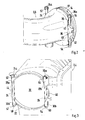
- the suction device shown schematically in Fig. 1 for a two-row Internal combustion engine with turbocharging, for example V8 turbo engine, consists of one each leading to an air filter housing 2 and 4 air line, which as Air manifold tube 6 and 8 is formed. Lead from the air filter housing 2 and 4, respectively two pipe connections 10 and 12 attached to the engine on the intake system Throttle body 14. Between the two air filters 2 and 4 and the Throttle body 14, two exhaust gas turbochargers 13 and 15 are arranged, the generated charge air is cooled by two downstream air coolers 16 and 18.
- Air filter housing 2 4 is in Air filter housing 2, 4 an opening 20 is provided, which by an annular collar 22nd is limited. On the collar 22 are as receiving elements for two locking pins 24 and 26 two upper bearing eyes 28a and 28b and two lower bearing eyes 30a and 30b provided.
- the air manifold tube 6, 8 has a flange portion 32 which in the assembled state in the annular collar 22 of the opening 20 of the air filter housing 2, 4 intervenes. To seal both components, the flange section 32 has a radial circumferential groove 34 into which an O-ring, not shown, is inserted.
- the Flange section 32 is adjacent to two laterally arranged bearing sleeves 36 (only one shown visibly) provided that both components are assembled - Air manifold pipe 6, 8 and air filter housing 2, 4 - from the two locking pins 24, 26 are penetrated.
- the two bearing sleeves 36 each have two inclines running end faces 40 and 42, which in the assembled state on the inner wall of the Ring collar 22 come to mind.
- the ring collar 22 is two each Recesses 44 and 46 provided as a stop for two laterally over the Flange section 32 protruding locking pin 48 (only one visible) serve. So that the insertion depth of the air manifold tube 6, 8 in the opening 20 of the Air filter housing 2, 4 limited so that the flange portion 32 completely in the Ring collar 22 takes place.
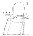
- the stop on the locking pin 48 is so coordinated that the in the upper and lower bearing eyes 28a and 30a or 28b and 30b provided openings with the in the two bearing sleeves 36th provided openings correspond or are aligned. So that for attaching the air elbow pipes 6, 8 to the air filter housing 2, 4 serving Locking pins 24 and 26 through the bearing eyes 28 and 30 and the bearing sleeves 36 be put through.
- the locking pins 24 and 26 each have a detent 52 and 54 at their ends on, as described in more detail below, for locking the attachment serve. So that the locking pins 24, 26 provided with the detent 52, 54 through those in the upper and lower bearing eyes 28a and 30a or 28b and 30b and in the Bearing sleeves 36 provided openings can be inserted, have the mentioned components each have an inner groove 56, with the help of which with the detent 52, 54 provided locking pins 24, 26 are inserted through the openings can. When the two locking pins 24, 26 through the openings have been inserted, the two locking pins 24, 26 by 180 ° rotated, whereby the locking lugs 52, 54 each in one on the lower bearing eyes 30a, 30b provided locking groove 58 and 60 come into engagement.
- an elastomer ring 62 and 64 is provided.
- the elastomer ring 62, 64 can the transfer of the locking pins 24, 26 to their locked position axially be squeezed together; when the locking lugs 52, 54 into the locking grooves 58, 60 intervene, the elastomer rings 62, 64 provide the permanent positive locking the component connection safely.
Landscapes
- Engineering & Computer Science (AREA)
- Chemical & Material Sciences (AREA)
- Combustion & Propulsion (AREA)
- Mechanical Engineering (AREA)
- General Engineering & Computer Science (AREA)
- Filtering Of Dispersed Particles In Gases (AREA)
- Control Of Throttle Valves Provided In The Intake System Or In The Exhaust System (AREA)
- Lubrication Details And Ventilation Of Internal Combustion Engines (AREA)
Applications Claiming Priority (2)
| Application Number | Priority Date | Filing Date | Title |
|---|---|---|---|
| DE10139435A DE10139435A1 (de) | 2001-08-10 | 2001-08-10 | Ansaugvorrichtung für eine Brennkraftmaschine |
| DE10139435 | 2001-08-10 |
Publications (3)
| Publication Number | Publication Date |
|---|---|
| EP1283351A2 true EP1283351A2 (fr) | 2003-02-12 |
| EP1283351A3 EP1283351A3 (fr) | 2003-11-12 |
| EP1283351B1 EP1283351B1 (fr) | 2006-12-13 |
Family
ID=7695101
Family Applications (1)
| Application Number | Title | Priority Date | Filing Date |
|---|---|---|---|
| EP02014380A Expired - Lifetime EP1283351B1 (fr) | 2001-08-10 | 2002-06-28 | Système d'admission pour un moteur à combustion interne |
Country Status (4)
| Country | Link |
|---|---|
| US (1) | US6755169B2 (fr) |
| EP (1) | EP1283351B1 (fr) |
| JP (1) | JP4358488B2 (fr) |
| DE (2) | DE10139435A1 (fr) |
Cited By (1)
| Publication number | Priority date | Publication date | Assignee | Title |
|---|---|---|---|---|
| DE102013203096A1 (de) * | 2013-02-26 | 2014-08-28 | Mahle International Gmbh | Saugmodulkombination |
Families Citing this family (7)
| Publication number | Priority date | Publication date | Assignee | Title |
|---|---|---|---|---|
| DE10350133A1 (de) * | 2003-10-28 | 2005-06-23 | International Engine Intellectual Property Company, LLC., Warrenville | Verbrennungsmotor mit wenigstens zwei Zylinderblöcken |
| US20060090725A1 (en) * | 2004-10-20 | 2006-05-04 | Garvey Paul W | Devices for connecting canister air cleaners to carburetors of internal combustion engines |
| US7556009B2 (en) * | 2007-09-07 | 2009-07-07 | Advanced Flow Engineering, Inc. | Air intake manifold for coupling the output of a compressor to the air intake of an internal combustion engine |
| US8807113B2 (en) * | 2009-05-04 | 2014-08-19 | Ford Global Technologies, Llc | Device and method for integrating an air cleaner into a radiator fan shroud |
| EP2596272A1 (fr) * | 2010-07-21 | 2013-05-29 | Ulo Systems L.L.C. | Agencement d'accouplement |
| US8677966B2 (en) * | 2011-01-20 | 2014-03-25 | Advanced Flow Engineering, Inc. | Air intake flow device and system |
| DE102017005444A1 (de) | 2017-06-07 | 2018-12-13 | Daimler Ag | Verbindungsanordnung einer Luftleitung an einem Verdichter eines Abgasturboladers für ein Kraftfahrzeug |
Family Cites Families (9)
| Publication number | Priority date | Publication date | Assignee | Title |
|---|---|---|---|---|
| GB406846A (en) * | 1932-12-20 | 1934-03-08 | Albert Sutcliffe | Improvements in or relating to dis-connectible couplings for pipes and tubes |
| US3141686A (en) * | 1958-11-24 | 1964-07-21 | Smith Blair Inc | Pipe coupling |
| US3149362A (en) * | 1960-11-01 | 1964-09-22 | Nat Union Electric Corp | Hose connector or coupling for suction cleaner |
| GB1448189A (en) * | 1974-05-15 | 1976-09-02 | Mann & Hummel Filter | Intake filter for internal combustion engines compressors and other air-intaking machaines |
| US4182121A (en) * | 1976-10-26 | 1980-01-08 | Chrysler Corporation | Exhaust tuning for transverse automobile engine |
| US4431218A (en) * | 1982-02-05 | 1984-02-14 | Dayco Corporation | Fluid coupling and method of making same |
| US5341773A (en) * | 1993-11-04 | 1994-08-30 | Ford Motor Company | Joint for an automative air induction system |
| US5595151A (en) * | 1995-12-11 | 1997-01-21 | Siemens Electric Limited | Releasable connection for molded parts |
| US5829793A (en) * | 1996-07-05 | 1998-11-03 | Phillips Petroleum Company | Self-restrained adapter system for connecting plastic pipe system to metallic pipe system |
-
2001
- 2001-08-10 DE DE10139435A patent/DE10139435A1/de not_active Ceased
-
2002
- 2002-06-28 DE DE50208935T patent/DE50208935D1/de not_active Expired - Lifetime
- 2002-06-28 EP EP02014380A patent/EP1283351B1/fr not_active Expired - Lifetime
- 2002-08-08 US US10/214,179 patent/US6755169B2/en not_active Expired - Lifetime
- 2002-08-08 JP JP2002231875A patent/JP4358488B2/ja not_active Expired - Fee Related
Cited By (2)
| Publication number | Priority date | Publication date | Assignee | Title |
|---|---|---|---|---|
| DE102013203096A1 (de) * | 2013-02-26 | 2014-08-28 | Mahle International Gmbh | Saugmodulkombination |
| US9885327B2 (en) | 2013-02-26 | 2018-02-06 | Mahle International Gmbh | Intake module combination |
Also Published As
| Publication number | Publication date |
|---|---|
| JP2003065172A (ja) | 2003-03-05 |
| EP1283351B1 (fr) | 2006-12-13 |
| DE50208935D1 (de) | 2007-01-25 |
| DE10139435A1 (de) | 2003-02-27 |
| US6755169B2 (en) | 2004-06-29 |
| JP4358488B2 (ja) | 2009-11-04 |
| US20030029407A1 (en) | 2003-02-13 |
| EP1283351A3 (fr) | 2003-11-12 |
Similar Documents
| Publication | Publication Date | Title |
|---|---|---|
| DE102011101506B4 (de) | Motoranordnung und Verfahren zur Herstellung | |
| EP3551315B1 (fr) | Disque d'extrémité, élément filtre à disque d'extrémité et système de filtration | |
| DE69605849T2 (de) | Anschlussleitung zwischen den zylindrischen Brennkammern und dem ringförmigen Einlass einer Gasturbine | |
| DE102012010939A1 (de) | Saugölfiltereinheit für Getriebe oder Verbrennungsmotoren | |
| WO2014056652A1 (fr) | Dispositif de raccordement destiné à un système d'alimentation en air frais | |
| EP4048426B1 (fr) | Dispositif de traitement pour traiter des fluides, en particulier des fluides liquides, et tête de raccordement pour un dispositif de traitement | |
| DE69300773T2 (de) | Motorlufteinlasssystem mit teleskopischem Drosselklappengehäuse. | |
| EP1283351A2 (fr) | Système d'admission pour un moteur à combustion interne | |
| DE3741250A1 (de) | Vorrichtung zum gegenseitigen verbinden von zwei leitungen, insbesondere kraftstoffleitungen | |
| WO2019115390A1 (fr) | Dispositif et procédé de raccordement de composants de conduite de fluide, en particulier dans la ligne de gaz d'échappement d'un véhicule automobile | |
| DE10123492B4 (de) | Ansaugvorrichtung für eine Brennkraftmaschine | |
| EP2839199A1 (fr) | Coupleur enfichable pour conduites de fluides | |
| DE60018436T2 (de) | Verbrennungsluftleitungskupplung | |
| EP2133615B1 (fr) | Dispositif de couplage, en particulier pour une installation d'air frais | |
| EP1870570A2 (fr) | Dispositif comprenant un échangeur de chaleur et un filtre pour liquide | |
| DE102016110772A1 (de) | Bauteilanordnung | |
| DE19637276A1 (de) | Kraftstoffördereinrichtung für Kraftfahrzeuge | |
| EP3414436B1 (fr) | Système de sortie de gaz d'échappement pour un véhicule automobile, véhicule automobile doté d'un tel système de sortie de gaz d'échappement et procédé de production d'un système de sortie de gaz d'échappement | |
| DE19512941C2 (de) | Vorrichtung zum Verbinden eines Abgasrückführsystems mit einer Sauganlage eines Verbrennungsmotors | |
| EP2910792A1 (fr) | Dispositif de liaison pour la liaison fluidique d'une section de tube de fluide avec une autre section de tube de fluide | |
| EP2818682B1 (fr) | Système de raccordement | |
| DE202012100550U1 (de) | Verbindungsvorrichtung zum Verbinden von Leitungselementen | |
| DE102007043441A1 (de) | Schlauchstutzen und Schlauchkupplung | |
| DE102023212772A1 (de) | Vorrichtung zur Schnellverbindung von mehreren fluidführenden Leitungsabschnitten mit einem oder mehreren Anschlussstutzen und Verbindungsanordnung | |
| DE102016101458A1 (de) | Anordnung eines Fixierelements an einer Fluidleitung sowie Fixierelement |
Legal Events
| Date | Code | Title | Description |
|---|---|---|---|
| PUAI | Public reference made under article 153(3) epc to a published international application that has entered the european phase |
Free format text: ORIGINAL CODE: 0009012 |
|
| AK | Designated contracting states |
Designated state(s): AT BE CH CY DE DK ES FI FR GB GR IE IT LI LU MC NL PT SE TR |
|
| AX | Request for extension of the european patent |
Extension state: AL LT LV MK RO SI |
|
| PUAL | Search report despatched |
Free format text: ORIGINAL CODE: 0009013 |
|
| AK | Designated contracting states |
Kind code of ref document: A3 Designated state(s): AT BE CH CY DE DK ES FI FR GB GR IE IT LI LU MC NL PT SE TR |
|
| AX | Request for extension of the european patent |
Extension state: AL LT LV MK RO SI |
|
| 17P | Request for examination filed |
Effective date: 20040512 |
|
| AKX | Designation fees paid |
Designated state(s): DE FR GB IT |
|
| 17Q | First examination report despatched |
Effective date: 20040701 |
|
| GRAP | Despatch of communication of intention to grant a patent |
Free format text: ORIGINAL CODE: EPIDOSNIGR1 |
|
| GRAS | Grant fee paid |
Free format text: ORIGINAL CODE: EPIDOSNIGR3 |
|
| GRAA | (expected) grant |
Free format text: ORIGINAL CODE: 0009210 |
|
| AK | Designated contracting states |
Kind code of ref document: B1 Designated state(s): DE FR GB IT |
|
| REG | Reference to a national code |
Ref country code: GB Ref legal event code: FG4D Free format text: NOT ENGLISH |
|
| REF | Corresponds to: |
Ref document number: 50208935 Country of ref document: DE Date of ref document: 20070125 Kind code of ref document: P |
|
| GBT | Gb: translation of ep patent filed (gb section 77(6)(a)/1977) |
Effective date: 20070314 |
|
| ET | Fr: translation filed | ||
| PLBE | No opposition filed within time limit |
Free format text: ORIGINAL CODE: 0009261 |
|
| STAA | Information on the status of an ep patent application or granted ep patent |
Free format text: STATUS: NO OPPOSITION FILED WITHIN TIME LIMIT |
|
| 26N | No opposition filed |
Effective date: 20070914 |
|
| REG | Reference to a national code |
Ref country code: FR Ref legal event code: TP |
|
| REG | Reference to a national code |
Ref country code: FR Ref legal event code: CD |
|
| REG | Reference to a national code |
Ref country code: FR Ref legal event code: TP |
|
| REG | Reference to a national code |
Ref country code: GB Ref legal event code: 732E Free format text: REGISTERED BETWEEN 20110310 AND 20110316 |
|
| REG | Reference to a national code |
Ref country code: GB Ref legal event code: 732E Free format text: REGISTERED BETWEEN 20110331 AND 20110406 |
|
| PGFP | Annual fee paid to national office [announced via postgrant information from national office to epo] |
Ref country code: FR Payment date: 20110630 Year of fee payment: 10 |
|
| PGFP | Annual fee paid to national office [announced via postgrant information from national office to epo] |
Ref country code: GB Payment date: 20110620 Year of fee payment: 10 |
|
| PGFP | Annual fee paid to national office [announced via postgrant information from national office to epo] |
Ref country code: IT Payment date: 20110623 Year of fee payment: 10 |
|
| GBPC | Gb: european patent ceased through non-payment of renewal fee |
Effective date: 20120628 |
|
| PG25 | Lapsed in a contracting state [announced via postgrant information from national office to epo] |
Ref country code: IT Free format text: LAPSE BECAUSE OF NON-PAYMENT OF DUE FEES Effective date: 20120628 |
|
| REG | Reference to a national code |
Ref country code: FR Ref legal event code: ST Effective date: 20130228 |
|
| PG25 | Lapsed in a contracting state [announced via postgrant information from national office to epo] |
Ref country code: GB Free format text: LAPSE BECAUSE OF NON-PAYMENT OF DUE FEES Effective date: 20120628 Ref country code: FR Free format text: LAPSE BECAUSE OF NON-PAYMENT OF DUE FEES Effective date: 20120702 |
|
| PGFP | Annual fee paid to national office [announced via postgrant information from national office to epo] |
Ref country code: DE Payment date: 20200618 Year of fee payment: 19 |
|
| REG | Reference to a national code |
Ref country code: DE Ref legal event code: R119 Ref document number: 50208935 Country of ref document: DE |
|
| PG25 | Lapsed in a contracting state [announced via postgrant information from national office to epo] |
Ref country code: DE Free format text: LAPSE BECAUSE OF NON-PAYMENT OF DUE FEES Effective date: 20220101 |